
Introduction

This chapter introduces you to creating 3D solid objects:
Other methods to create 3D solid objects include:
- Extruding 2D entities
- Revolving 2D entities around an axis
- Sweeping 2D entities along a path
- Lofting between existing 2D entities
- Thickening surfaces
To create more complex 3D solid objects you can edit solids by using Boolean operations:
This chapter further describes commands to edit and inquire 3D solid objects with the following methods:
- Filleting edges of 3D solids
- Chamfering edges of 3D solids
- Modifying 3D solids by pushing and pulling geometry
- Modifying the edges, faces, and bodies of 3D solids
- Slicing 3D solids
- Creating sections of 3D solids
- Checking interferences of 3D solids
- Displaying mass properties of 3D solids and regions
After they are created, you can modify 3D solid objects with EntityGrips or the Properties palette:
Creating Solids
This section discusses:
- Creating Boxes
- Creating Wedges
- Creating Pyramids
- Creating Spheres
- Creating Cones
- Creating Cylinders
- Creating Tori
- Creating PolySolids
- Creating Planar Surfaces
- Creating 3D Solids and 3D Surfaces by Extruding 2D Entities
- Creating 3D Solids by Revolving 2D Entities Around an Axis
- Creating 3D Solids by Sweeping 2D Entities Along a Path
- Creating 3D Solids by Lofting Between 2D Entities
- Creating 3D Solids by Thickening Surfaces
Creating Boxes
Use the Box command to create a 3D solid box. The base of the box is parallel to the XY-plane of the coordinate system.
To create a box by specifying its corners:
- Click Solids > Draw > Box (or type Box).
- Click in the graphics area or type a value to specify the first corner of the box.
- Repeat the previous step for the other corner.
- Specify a value for height
– or –
Type 2p to click two points in the graphics area to specify the height.
To create a box by specifying a center point:
- Click Solids > Draw > Box (or type Box).
- Enter the Center option.
- Click in the graphics area or type a value to specify the center of the box.
- Repeat the previous step for the corner.
- Type a value for height.
– or –
Type 2p to click two points in the graphics area to specify the height.
To create a cube:
- Click Solids > Draw > Box (or type Box).
- Click in the graphics area, type a value to specify the first corner of the box, or enter the Center option and specify the center of the box.
- Enter the Cube option.
- Click in the graphics area or type a value for length, then press Enter.
To create a box of varying length, width, and height:
- Click Solids > Draw > Box (or type Box).
- Click in the graphics area or type a value to specify the first corner of the box, or type c and specify the center of the box.
- Enter the Length option.
- Click in the graphics area or type a value for length, then press Enter.
The length corresponds to the X-axis.
- Click in the graphics area or type a value for width, then press Enter.
The width corresponds to the Y-axis.
- Click in the graphics area or type a value for height, then press Enter.
The height corresponds to the Z-axis.
Access
Command: Box
Menu: Solids > Draw > Box
Ribbon: 2D Drafting > Modeling > (Flyout) Box
Ribbon: 2D Drafting > Mesh > (Flyout) Box
Creating Wedges
The Wedge command creates a five-sided 3D solid with a sloped face tapering along the X axis. A wedge is like a box cut diagonally in half.
The base of the wedge is drawn parallel to the XY-plane of the coordinate system.
To create a wedge by specifying its corners:
- Click Solids > Draw > Wedge (or type Wedge).
- Click in the graphics area to specify the first corner of the wedge or type the 3D coordinates.
- Click to specify the other corner.
- Specify a value for height
- – or –
- Type 2p to click two points in the graphics area to specify the height.
To create a wedge by specifying a center point:
The Center option lets you create a solid wedge by specifying a center point and a corner point of the wedge for the base face.
- Click Solids > Draw > Wedge (or type Wedge).
- Enter the Center option.
- Click in the graphics area to specify the center of the wedge or type the 3D coordinates.
- Repeat the previous step for the opposite corner.
- Click in the graphics area to specify the first and second points, or type a value for height.
To create a wedge in the form of a cube:
- Click Solids > Draw > Wedge (or type Wedge).
- Click in the graphics area to specify the first corner of the wedge, or enter the Center option and specify the center of the wedge, or type the 3D coordinates.
- Enter the Cube option.
- Click in the graphics area to specify the first and second points, or type a value for length.
To create a wedge of various length, width, and height:
- Click Solids > Draw > Wedge (or type Wedge).
- Click in the graphics area to specify the first corner of the wedge, or type c and specify the center of the wedge, or type the 3D coordinates.
- Enter the Length option.
- Click twice in the graphics area or type a value for length. The length corresponds to the X-axis.
- Click twice in the graphics area or type a value for width. The width corresponds to the Y-axis.
- Click twice in the graphics area or type a value for height. The height corresponds to the Z-axis.
Access
Command: Wedge
Menu: Solids > Draw > Wedge
Ribbon: 2D Drafting > Modeling > (Flyout) Wedge
Ribbon: 2D Drafting > Mesh > (Flyout) Wedge
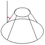
Creating Pyramids
Use the Pyramid command to create a 3D solid pyramid or a pyramid frustum. The pyramid base is parallel to the XY-plane of the coordinate system. The height is perpendicular to the base and parallel to the Z-axis.
To create a pyramid:
- Click Solids > Draw > Pyramid (or type Pyramid).
- Specify the center point of the base or enter an option:
- Edge: Lets you define the edge of the pyramid base by specifying edge endpoints.
- Sides: Lets you change the number of sides of the pyramid. Any whole number between 3 and 32 is valid.
- Specify the base radius or enter an option:
- Inscribed: Defines the radius with an inscribed circle rather than a circumscribed circle.
- Specify the height or enter an option:
- 2Point: Lets you click two points or enter their coordinates to specify the height.
- Axis endpoint: Lets you click a point or enter the coordinates for the endpoint of the pyramid.
- Top radius: Lets you create a pyramid frustum by defining the radius of the upper pyramid base.
Access
Command: Pyramid
Menu: Solids > Draw > Pyramid
Ribbon: 2D Drafting > Modeling > (Flyout) Pyramid
Ribbon: 2D Drafting > Mesh > (Flyout) Pyramid
Creating Spheres
The Sphere command creates a 3D solid sphere.
The center point is related to the coordinate system. The generation of the sphere depends on the coordinate system too, even if the sphere seems to be independent from any direction. The segmentation of the sphere occurs differently in the angle directions (latitude and longitude).
To create a sphere:
- Click Solids > Draw > Sphere (or type Sphere).
- Click in the graphics area to specify a center point or type the 3D coordinates.
- Set the radius by clicking in the graphics area or typing a value. The distance between the center point and the point picked is used for the radius.
- – or –
- Enter the Diameter option, then set the diameter by pointing in the graphics area or typing a value.
Access
Command: Sphere
Menu: Solids > Draw > Sphere
Ribbon: 2D Drafting > Modeling > (Flyout) Sphere
Ribbon: 2D Drafting > Mesh > (Flyout) Sphere
Creating Cones
Use the Cone command to draw a 3D solid cone with a symmetrical or offset apex. The base plane of the cone can be circular or elliptical. The ground plane of the cone lies in the XY-plane of the coordinate system. The height of the apex is related to the Z-axis of the coordinate system.
To create a cone:
- Click Solids > Draw > Cone (or type Cone).
- Set an option for the cone’s base:
- Center point base:
- Click in the graphics area to specify a center point or type the 3D coordinates.
- Click in the graphics area or type a value for radius.
– or –
Enter the Diameter option and click in the graphics area or type a value for diameter.
- 3-point base:
- Enter the 3Point option.
- Click in the graphics area or type values to specify the 3 points.
- 2-point diameter base:
- Enter the 2Point option.
- Click in the graphics area or type values to specify the first and second endpoints of the diameter.
- Tangent, tangent, radius (TTR) base:
- Enter the TTR option.
- Select a point on a circle, arc, or line for the first and second tangents.
- Type a value for radius.
- Elliptical base:
- Enter the Elliptical option.
- Click in the graphics area or type values to specify the axis endpoints and the length of the other axis.
– or –
Enter the Center option, then click in the graphics area to specify the center point, endpoint, and other axis. You can also type the 3D coordinates for the center point.
- Center point base:
- Set the cone height:
- Click in the graphics area or type a value.
– or –
- Enter the Apex option, then click in the graphics area or type a 3D coordinate for the apex point.
- Click in the graphics area or type a value.
Access
Command: Cone
Menu: Solids > Draw > Cone
Ribbon: 2D Drafting > Modeling > (Flyout) Cone
Ribbon: 2D Drafting > Mesh > (Flyout) Cone
Creating Cylinders
Use the Cylinder command to create a solid 3D cylinder. The base of the cylinder is parallel to the XY-plane of the coordinate system. The height is perpendicular to the base and parallel to the Z-axis.
To create a cylinder:
- Click Solids > Draw > Cylinder (or type Cylinder).
- Set an option for the cylinder’s base:
- Center point base:
- Click in the graphics area to specify a centerpoint or type the 3D coordinates.
- Click in the graphics area or type a value for radius. The distance between the center point and the point picked is used for the radius.
- – or –
- Enter the Diameter option, then click in the graphics area or type a value for diameter.
- 3-point base (with a base that runs through the 3 points):
- Enter the 3Point option.
- Click in the graphics area or type values to specify the 3 points. The order in which you enter the points is arbitrary.
- 2-point diameter base (with two points that define the diameter and position of the cylinder):
- Enter the 2Point option.
- Click in the graphics area or type values to specify the first and second endpoints of the diameter.
- Tangent, tangent, radius (TTR) base:
- Enter the TTR option.
- Select a point on a circle, arc, or line for the first and second tangents.
- Click in the graphics area or type a value for radius.
- Tangent, tangent, tangent (TTT) base:
- Enter the TTT option.
- Select a point on a circle, arc, or line for the first, second, and third tangents.
- Elliptical base:
- Enter the Elliptical option.
- Click in the graphics area or type values to specify the axis endpoints and the length of the other axis.
- – or –
- Enter the Center option, then (instead of defining the two endpoints of the ellipse axis) enter the center point of the axis followed by the length of the major and minor axis. Then click in the graphics area or type values to specify the center point, axis endpoint, and other axis.
- Center point base:
- Click in the graphics area or type values to specify the cylinder height. When you specify a height, the top center point is directly above the base center point along the Z-axis.
- – or –
- If you want the center of the top face of the cylinder to lie somewhere else, enter the Center of other end option. Click in the graphics area or type a value to specify a 3D point for the center point of the top face.
Access
Command: Cylinder
Menu: Solids > Draw > Cylinder
Ribbon: 2D Drafting > Modeling > (Flyout) Cylinder
Creating Tori
The Torus command creates a 3D solid torus. A torus is like a ring with a thickness.
The torus is drawn parallel to the XY-plane of the coordinate system.
To create a torus:
- Click Solids > Draw > Torus (or type Torus).
- Set options for how you want to create the torus:
- Center of torus:
- Click in the graphics area to specify a center point or type the 3D coordinates.
- Click in the graphics area or type a value for radius.
- – or –
- Enter the Diameter option, then click in the graphics area or type a value for diameter.
- 3 points (The centerline of the torus runs through the 3 points):
- Enter the 3Point option.
- Click in the graphics area or type values to specify the 3 points. The order in which you enter the points is arbitrary.
- 2 points: (The torus of the cylinder is set by 2 points that define the diameter and position of the torus):
- Enter the 2Point option.
- Click in the graphics area or type values to specify the first and second end points of the diameter.
- Tangent, tangent, radius (TTR):
- Enter the TTR option.
- Select a point on a circle, arc, or line for the first and second tangents.
- Click in the graphics area or type a value for radius.
- Tangent, tangent, tangent (TTT):
- Enter the TTT option.
- Select a point on a circle, arc, or line for the first, second, and third tangents.
- Center of torus:
- Click in the graphics area or type a value for the tube radius.
- – or –
- Enter the Diameter option, then click in the graphics area or type a value for diameter.
Access
Command: Torus
Menu: Solids > Draw > Torus
Ribbon: 2D Drafting > Modeling > (Flyout) Torus
Ribbon: 2D Drafting > Mesh > (Flyout) Torus
Creating PolySolids
Use the PolySolid command to draw 3D solids in the shape of polygonal walls.
PolySolids can contain straight and curved segments of a specified height and width.
To create PolySolids, use one of these methods:
- Specify vertices, one by one.
- Convert existing 2D entities, such as Lines, PolyLines, Arcs, Circles, Ellipses, and Splines.
PolySolid entities are 3D solids that you can modify using editing commands for 3D solids.
To create PolySolids by specifying vertices:
- Click Solids > Draw > PolySolid (or type PolySolid).
- Optionally, specify the following:
- Height. Specify the height of the PolySolid.
- Width. Specifies the width of the PolySolid.
- Justify. Specifies the PolySolid placement relative to the line that defines the PolySolid (Center, Left, or Right).
- In the graphics area, specify the start point for the first segment of the PolySolid.
- Specify options for the next segment:
- Arc. Changes the segment type to an Arc.
- Undo. Undoes a previous segment.
- Specify the segment end point.
- Do one of the following:
- Specify each successive segment according to steps 4 and 5.
- After specifying at least two segments, specify the Close option to create a closed PolySolid, or press Enter.
To create PolySolids from existing entities:
- Click Solids > Draw > PolySolid (or type PolySolid).
- Optionally, specify the following:
- Height. Specify the height of the PolySolid.
- Width. Specifies the width of the PolySolid.
- Justify. Specifies the PolySolid placement relative to the entity that defines the PolySolid (Center, Left, or Right).
- Specify the Entity option.
- In the graphics area, specify the entities to convert and press Enter.
- Press Enter.
The PolySolid is created with the specified height and width.
 To avoid to create single PolySolids from consecutive lines and arcs, use PolyLines as base entities.
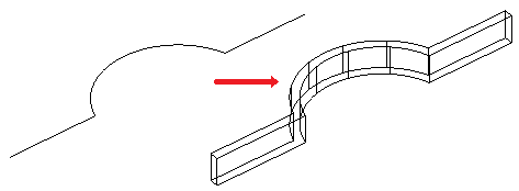
Access
Command: PolySolid
Menu: Solids > Draw > PolySolid
Ribbon: 2D Drafting > Modeling > (Flyout) PolySolid
Creating Planar Surfaces
Use the PlaneSurf command to create rectangular planar surfaces.
To create a planar surface by specifying its corners:
- Click Solids > Draw > Planar Surface (or type PlaneSurf).
- Specify the first corner of the planar surface.
- Specify the opposite corner of a rectangle.
- A rectangular planar surface is created parallel to the current coordinate system.
To create a planar surface from an existing object:
- Click Solids > Draw > Planar Surface (or type PlaneSurf).
- Enter the Objects option to specify objects.
- Select entities that form enclosed areas.
Access
Command: PlaneSurf
Menu: Solids > Draw > Planar Surface
Ribbon: 2D Drafting > Modeling > (Flyout) Planar Surface
Creating 3D Solids and 3D Surfaces by Extruding 2D Entities
The Extrude command creates solid primitives by extruding closed 2D entities such as PolyLines, Circles, Ellipses, and Regions.
Use the Extrude command to create 3D solids or 3D surfaces.
To extrude entities, use one of these methods:
-
Specify the path for extrusion
Specify the entity to extrude and a path defining the shape of the extrusion. The entity follows the path to create 3D solids or 3D surfaces.
The extrusion starts from the plane of the entity and maintains its orientation relative to the path.
-
Specify the taper angle.
Specify the entity to extrude and a taper angle. The taper angle is between -90 and +90 degrees. The sign of the taper angle specifies the taper direction. A taper angle of 0 degrees extrudes a 2D entity that is perpendicular to its 2D plane.
To create an extrusion:
- Click Solids > Draw > Extrude (or type Extrude).
- Type Extrude at the command prompt.
- Specify the type of model to create.
- Surface. Creates surfaces from the selected entities.
- Solid. Creates 3D solids from the selected entities.
- Specify the entities to extrude.
- Specify a height for the extrusion. All entities use the same height.
The software extrudes the entity and creates a 3D solid.
To extrude an entity along a path:
- Click Solids > Draw > Extrude (or type Extrude).
- Specify the type of model to create.
- Surface. Creates surfaces from the selected entities.
- Solid. Creates 3D solids from the selected entities.
- In the graphics area, specify the entities to extrude and press Enter.
- Specify the Path option.
- Specify an entity for the extrusion path.
To extrude an entity with a taper angle:
- Click Solids > Draw > Extrude (or type Extrude).
- Type Extrude at the command prompt.
- Specify the type of entities to create.
- Surface. Creates surfaces from the selected entities.
- Solid. Creates 3D solids from the selected entities.
- Specify the entities to extrude and press Enter.
- Specify the Taper angle option.
- Specify the taper angle and press Enter.
- Specify the extrusion height.
Access
Command: Extrude
Menu: Solids > Draw > Extrude
Ribbon: 2D Drafting > Modeling > (Flyout) Extrude
Creating 3D Solids by Revolving 2D Entities Around an Axis
Use the Revolve command to create a 3D solid by revolving a 2D object about an axis.
To revolve entities about an axis:
- Click Solids > Draw > Revolve (or type Revolve).
- Specify entities to revolve and press Enter.
- Specify the start point for the axis of revolution.
- Specify the endpoint of the axis of revolution.
- Specify the angle of revolution (default: 360 degrees).
To revolve entities about an axis defined by an object:
- Click Solids > Draw > Revolve (or type Revolve).
- Specify entities to revolve and press Enter.
- Enter the Object option to choose an entity that determines the axis of revolution.
- Select the object.
- Specify the angle of revolution (default: 360 degrees).
To revolve entities about the positive X- or Y-axis:
- Click Solids > Draw > Revolve (or type Revolve).
- Specify entities to revolve and press Enter.
- Type X or Y to use the positive X- or Y-axis of the current custom coordinate system as axis direction.
- Specify the angle of revolution (default: 360 degrees).
Access
Command: Revolve
Menu: Solids > Draw > Revolve
Ribbon: 2D Drafting > Modeling > (Flyout) Revolve
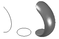
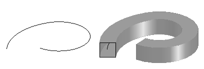
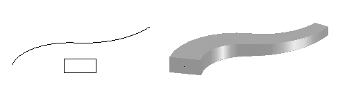
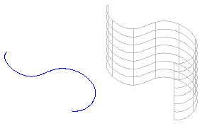
Creating 3D Solids by Sweeping 2D Entities Along a Path
The Sweep command lets you create unique solid primitives or surfaces by sweeping existing two-dimensional entities along a path. You can sweep more than one entity along the path. The entities must lie on the same plane.
Sweeping entities along closed curves as paths creates solid objects, while sweeping entities along lines or open boundaries creates surfaces.
You can sweep the following entities:
- Splines, Polylines, and Lines
- 2D Solids
- Arcs and Circles
- Ellipses and elliptical Arcs
- Regions
- Trace
Note: The entities to sweep can be in any arrangement, for example, adjacent or nested.
You can use as path the following entities:
- Splines, open Polylines, and Lines
- Helix
- Arcs and Circles
- Ellipses and elliptical Arcs
- Any closed curve
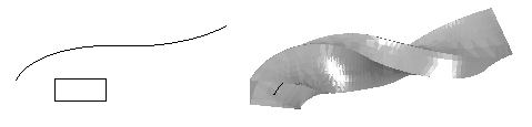
Sweeping Properties
In the Properties palette, you can specify the following properties of the swept entity:
- Profile rotation. Rotates the surface or the solid about the path with the specified angle.
- Scale along path. Specifies a scale factor of the end of the resulted entity compared to the start of the resulted entity.
- Twist along path. Specifies the angle of rotation of the endpoint compared to the start point for the created entity.
To create a solid or surface by sweeping an object along a path:
- Click Solids > Draw > Sweep (or type Sweep).
- Optionally, use the Type option to specify whether to create a surface or a solid.
- Select the entities to sweep and press Enter.
Note: You can specify one or more entities in any arrangement (adjacent, nested entities).
- Select the entities which determine the sweep path.
- – or –
- Use Alignment, Base point, Scale, and Twist to specify options for sweeping and then select the entities which determine the sweep path:
-
Alignment: Unless you determine otherwise, the entities to be swept are aligned perpendicular to the path.
- Base Point: Specifies a base point for the entities to be swept.
-
Scale: Specifies a scale factor for the entities to be swept. Scaling is applied from the startpoint to the endpoint of the path. Optionally, you can use the Reference option to scale the specified entities based on the specified reference length.
-
Twist: Sets a twist angle for the for the entities to be swept along the total length of the path. The twist angle specifies the amount of rotation along the sweep path. Optionally, you can use the Bank option to allow the entity to sweep to rotate along the sweep path.
-
Alignment: Unless you determine otherwise, the entities to be swept are aligned perpendicular to the path.
Access
Command: Sweep
Menu: Solids > Draw > Sweep
Ribbon: 2D Drafting > Modeling > (Flyout) Sweep
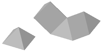
Creating 3D Solids by Lofting Between 2D Entities
The Loft command lets you create a new solid object or surface by specifying a series of cross sections.
The cross section shapes – together with a path or multiple guides, if specified – define the profile of the resulting solid object or surface.
If the entities defining the cross sections are closed, the command creates a solid object; otherwise if the cross sections is open, it creates a surface.
To create a solid or surface by lofting existing entities:
- Click Solids > Draw > Loft (or type Loft).
- Specify an option:
- Point. Specifies the first or the last point.
- Type. Specifies whether the lofted entity is a solid or a surface.
- Specify shapes individually in lofting order and press Enter. You must specify at least two cross sections.
- Specify an option:
- Cross-sections only: Use cross sections defined by arcs, lines, polylines, or polygons. If you specify closed polylines or circles as cross sections, you can create a solid object in the space between the cross sections.
- Guides: Specify multiple entities defining guides that intersect each cross section to determine the shape of the solid or surface. You can use the following entities: Line, Spline, Arc, Ellipse, and Elliptical arc.
- Path: Specify an entity defining a single path curve to determine the shape of the solid or surface. You can use the following entities: Spline, 3D Helix, Line, Polyline with one segment, Arc, Circle, Ellipse and elliptical arc, Lines.
-
Settings: Displays the Loft Options dialog box. Specify the following:
- Select one of the surfacing options:
- Ruled: The solid object or surface is ruled between the cross sections. The resulting object has sharp edges at all cross sections.
- Smooth fit: A smooth solid or surface is drawn between the cross sections. The resulting object has sharp edges at the starting and ending cross sections.
- Normal to: Specifies whether the surface normal is normal to the start cross section, to the end cross section, to both start and end cross section, or to all cross sections.
- Draft angles: Specifies the draft angle and magnitude of the first and last cross sections for the lofted solid object or surface.
- Close geometry: Closes or opens a torus-formed solid object or surface.
- Show preview: Displays a preview in the graphics area.
- Select one of the surfacing options:
A solid object or surface is created by lofting through of two or more cross section curves.
Access
Command: Loft
Menu: Solids > Draw > Loft
Ribbon: 2D Drafting > Modeling > (Flyout) Loft
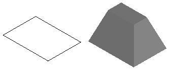
Creating 3D Solids by Thickening Surfaces
The Thicken command lets you create 3D solids from surfaces by thickening them.
To create a 3D solid by thickening a surface:
- Click Solids > Solid Editing > Thicken (or type Thicken).
- Select drawing objects of type surface to be converted to 3D solids.
Entities which are no surfaces are ignored by the command.
- Specify the thickness for the new solid object.
- The solid is created and the original surface becomes part of the new body.
Access
Command: Thicken
Menu: Solids > Solid Editing > Thicken
Ribbon: 2D Drafting > Solid Editing > Thicken
Modifying Solids
This section discusses:
- Viewing and Modifying Solid Properties
- Using EntityGrips to Modify Solids:
- Unifying 3D Solids or Regions
- Subtracting 3D Solids or Regions
- Intersecting 3D Solids or Regions
- Filleting Edges of 3D Solids
- Chamfering Edges of 3D Solids
- Modifying 3D Solids by Pushing and Pulling Geometry
- Modifying the Edges, Faces, and Bodies of 3D Solids
- Slicing 3D Solids
- Checking Interferences of 3D Solids
- Creating Sections from 3D Solids
- Displaying Mass Properties of 3D Solids and Regions
Viewing and Modifying Solid Properties
Use the Properties palette to view and modify solid properties.
To view and modify properties using the Properties palette:
- Click Modify > Properties (or type Properties).
- In the graphics area, select one or more solids.
The Properties palette displays the solid properties including the data that define the geometry.
- If you selected no solid or other entity, the palette displays only general solid properties (Layer, LineColor, LineScale, LineStyle, LineWeight, Transparency, and Hyperlink).
- If you selected only one solid, you can modify any property of the solid.
- If you selected more than one solid, the palette displays those properties common to all selected solids, such as Layer, LineColor, LineScale, LineStyle, LineWeight, Transparency, and Hyperlink. If the common properties are not identical in all of the selected entities, the corresponding drop-down list or field in the palette displays <<Varies>>.
- Update the properties of the selected entities by clicking the drop-down lists or entering new values.
Note: You can drag the Properties palette to create a separate window or anchor it to the left or right of the graphics area. Also, you can use other Properties palette display options to increase the graphics area.
Solid Properties
The Properties palette groups the parameters in the following categories:
General
Groups the general solid properties (Layer, LineColor, LineScale, LineStyle, LineWeight, Transparency, and Hyperlink).
Solid History
Controls the display of solids that form the composite solid or the components that have been removed.
For a composite solid, you can choose to record the sub components that have been removed from the solid.
Geometry
Displays the data defining the solid geometry. The set of parameters varies according to the solid type.
Use the parameters to modify the dimensions and modify the shape of primitive solids.
Examples:
- To change a cone to a frustum, set the Top radius property.
- To change the number of sides of a pyramid, set the Sides property.
Access
Command: Properties
Menu: Modify > Properties
Using EntityGrips to Modify Solids
You can manipulate solids by modifying them with EntityGrips (EGrips). In the graphics area, you select a solid, select an EntityGrip, then modify the solid.
You use EntityGrips to drag defining points of solids to new positions (stretching), or to move, rotate, scale, mirror, or copy entire solids.
Using EGrips, you can edit the following types of solids:
-
Primitive solids
Use EGrips displayed on each primitive solid to modify the position, size, and shape of primitive solids. For example, you can change the height of a pyramid or the size of its base.
-
Solids defined by extruding closed 2D entities
Use EGrips displayed on the solid profile (the closed 2D entity defining the solid) to modify the shape.
-
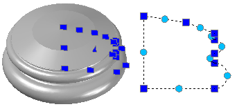
Solids defined by revolving closed 2D entities
Use EGrips displayed on the revolved 2D entity to modify the profile of the solid surface.
Use EGrips at the axis of revolution endpoint to relocate the solid.
Use the arrow EGrip to modify the revolution angle.
-
Solids defined by sweeping closed 2D entities
Use EGrips displayed on the swept 2D entity to modify the solid profile.
Use EGrips on the sweep path to modify the profile curve.
-
Lofted solids and surfaces
The solids display EGrips on their defining lines or curves according to the creation method.
- Cross section. You can drag EGrips on any defining lines or curves to modify the shape.
- Path. You can edit the path only.

-
Composite solids
Use EGrips displayed on the composite solids to move the solid to a new location.
Modifying Solids Using EntityGrips
You use EntityGrips to drag defining points of solids to new positions (stretching), or to move, rotate, and scale solids.
You can modify solids with EntityGrips when no command is active. You select solids before you specify editing options.
The location of EntityGrips depends on the solid. For the EGrip nodes on particular solids, see Applying EntityGrip Nodes.
To stretch with base point and copy solids with EntityGrips:
- In the graphics area, select a solid.
The solid changes to dotted outlines, and the selectable handles appear on the entities (blue by default, called “cold grips”).
- Click an EGrip.
The EGrip changes color (red by default, called “hot grips”), and the EGrip options appear in the command window.
- Stretch the solid by moving the activated EGrip to another location and click on the drawing.
For EGrip edit mode, you can set:
- Stretch point. Specifies a new point location for the highlighted EGrip.
- Base point. Specifies a base point other than the highlighted base EGrip.
- Copy. Leaves the specified solid at its current location as you modify a copy.
- Undo. Cancels the previous EGrip editing action as long one or more EGrips are highlighted.
- Exit. Terminates EGrip editing. Highlighted modification EGrips disappear, but selection EGrips are still displayed.
Note: To clear EGrips from the specified solid or set of solids, press Esc.
To stretch, move, rotate and scale solids with EntityGrips:
- In the graphics area, select solids to modify.
- Click an EGrip.
- Press the Spacebar repeatedly to cycle through the following commands:
-
**STRETCH**. Stretches the solid from the selected EGrip location to the destination point you specify.
Unlike other commands, stretching modifies only one solid.
- **MOVE**. Moves the solids from the EGrip location to the destination point you specify.
- **ROTATE**. Rotates the solids about the EGrip as an axis with the rotation angle you specify.
- **SCALE**. Scales the solids with the selected EGrip as a base point with the scale factor you specify.
-
**STRETCH**. Stretches the solid from the selected EGrip location to the destination point you specify.
- Specify the modification point, rotation angle, or scale factor according to the command you selected.
You can also use the options Base point, Copy, Undo, and Exit (see above), before you complete the command.
To stretch multiple solids using EntityGrips:
- In the graphics area, select solids to modify.
The selectable handles appear on the solids as “cold grips.”
-
Shift + click several EGrips to highlight them.
The specified EGrips change color and appear as “hot grips.”
- Release Shift.
- Specify one EGrip as the base grip.
- Move the base grip to another location and click on the drawing.
Note: EntityGrips are not accessible on drawing entities on locked Layers.
Applying EntityGrip Nodes
EntityGrips (EGrips) are selectable handles displayed as small squares at the end points, centers, vertices, insertion points, and other geometric points of solids.
Every solid displays some EntityGrips after selection. You can edit the solids by dragging them. Their shape specifies how the EGrip changes the solid.
There are two types of EGrips:
- Corner EGrips (squares): modify the solid by stretching in any direction or change the location of the solid.
- Arrow EGrips (triangles): modify the solid by stretching the EGrip forward or backward.
When selected, EGrips change to red.
This table lists entities that have EGrips, where they are located, and the result of how the EGrips modify the entity.
EntityGrip Nodes and Editing Results
| Entity | Location | Result |
|---|---|---|
Box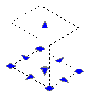
|
Base center | Moves the box |
| Four base corners | Modifies the length and width of the box | |
| Base midpoints (arrow EGrips) | Modifies the length and width of the box in the direction of the arrow | |
| Top and bottom (arrow EGrips) | Modifies the height of the box in the direction of the arrow | |
Wedge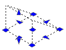
|
Base center | Moves the wedge |
| Four base corners | Modifies the length and the width of the wedge base | |
| Base midpoints (arrow EGrips) | Modifies the length and width of the wedge base in the direction of the arrow | |
| Top and bottom (arrow EGrips) | Modifies the height of the wedge in the direction of the arrow | |
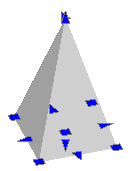
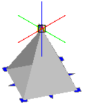
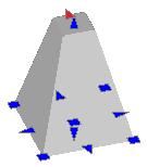
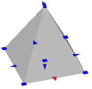
Pyramid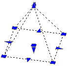
|
Base center | Moves the pyramid |
| Base corners, Base midpoints | Modifies corners and sides uniformly. Note: You cannot modify one corner or one side individually. |
|
| Top point (apex EGrip) | Modifies the height of the pyramid | |
| Top point (radius EGrip) | Modifies the pyramid shape (truncated pyramid) | |
| Note: You cannot modify the number of sides using EGrips. Use the Properties palette to specify any number of sides. | ||
Sphere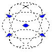
|
Center | Moves the sphere |
| Four circumference points | Modifies the diameter of the sphere | |
Cone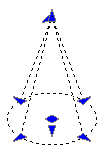
|
Base center | Moves the cone |
| Top point (apex EGrip) | Modifies the height of the cone in the direction of the arrow | |
| Top point (radius EGrip) | Modifies the cone shape (truncated cone) | |
| Four circumference points | Modifies the base radius of the cone | |
| Bottom arrow EGrip | Modifies the height of the cone in the direction of the arrow | |
Cylinder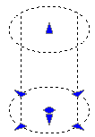
|
Base center | Moves the cylinder |
| Four circumference points | Modifies base radius of the cylinder | |
| Top and bottom (arrow EGrip) | Modifies the height of the cylinder in the direction of the arrow | |
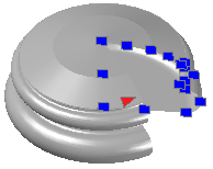
Torus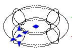
|
Center | Moves the torus |
| Section center (arrow EGrip) | Modifies the radius of the torus | |
| Four circumference points | Modify the radius of the tube | |
Unifying 3D Solids or Regions
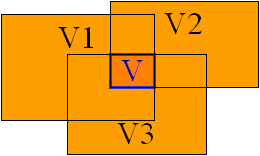
The Union command creates a composite region or solid by addition.
To unify regions or 3D solids to one object:
- Click Solids > Solid Editing > Union (or type Union).
- Select the regions or 3D solids to join to one object and press Enter.
- To unify the selected objects, they must touch each other or overlap.
- Based on this selection set the new object is created. The source objects are deleted.
Access
Command: Union
Menu: Solids > Solid Editing > Union
Ribbon: Home > Solid Editing > Boolean > Union
Subtracting 3D Solids or Regions
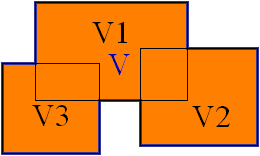
The Subtract command creates a composite region or a 3D solid by subtraction.
To subtract regions or 3D solids from each other:
- Click Solids > Solid Editing > Subtract (or type Subtract).
- Select the regions or 3D solids to subtract from.
- Select the regions or 3D solids to subtract and press Enter.
- From the objects in the first selection all objects in second selection are subtracted. The original objects are deleted.
Note: If a selection set contains more than one object, the union operation is applied to it first:
Vresult = (V1[Set1] + V2[Set1] + .. + Vi[Set1]) – (V1[Set2] + V2[Set2] + .. + Vj[Set2])
Access
Command: Subtract
Menu: Home > Solid Editing > Boolean > Subtract
Intersecting 3D Solids or Regions
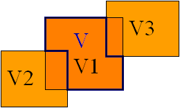
The Intersect command creates regions or 3D solids from the intersection regions or of 3D solids.
To intersect regions or 3D solids:
- Click Solids > Solid Editing > Intersect (or type Intersect).
- Select the regions or 3D solids to intersect and press Enter.
- Based on this selection set the new object is created. The selected objects have to overlap. The original objects are deleted. If a selection contains more than one object, these objects are unified before they are intersected.
Access
Command: Intersect
Menu: Home > Solid Editing > Boolean > Intersect
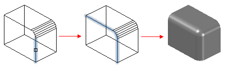
Filleting Edges of 3D Solids
Use the FilletEdges command to create rounded edges on 3D solid objects. You can apply fillets to specified edges or to all edges of the specified faces and specify the fillet radius.
To apply fillets to specified edges, use one of these methods:
- Specify edges one by one
- Specify an edge tangent to an existing filletted edge
To apply fillets to all edges of one or multiple faces, use one of these methods:
- Specify a point inside a face boundary
- Specify an edge of a face to apply fillets to all edges. For any edge, you can specify one of the adjacent faces.
To fillet edges of 3D solids:
- Click Solids > Solid Editing > Fillet edges (or type FilletEdges).
- Specify the Radius option.
- Specify the radius of the fillet arc.
- Specify the edges of 3D solids and press Enter.
The software fillets the edges by the specified radius.
To fillet multiple edges of a 3D solid using the Chain option:
- Click Solids > Solid Editing > Fillet edges (or type FilletEdges).
- Specify the Radius option.
- Specify the radius of the fillet arc.
- Specify the Chain option.
- Specify an edge tangent to an existing fillet on a 3D solid.
The software highlights all edges that are tangent to the fillet.
- Press Enter.
The software fillets all highlighted edges by the specified radius.
To fillet all edges of a face using the Loop option:
- Click Solids > Solid Editing > Fillet edges (or type FilletEdges).
- Specify the Radius option.
- Specify the radius of the fillet arc.
- Specify the Loop option.
- Specify the loop edge.
The software highlights a face that is adjacent to the edge.
- Specify the Accept option to confirm the current face selection or specify the Next face.
The software fillets the edges of the face by the specified radius.
To fillet all edges of specified faces using the Face option:
- Click Solids > Solid Editing > Fillet edges (or type FilletEdges).
- Specify the Radius option.
- Specify the radius of the fillet arc.
- Specify the Face option.
- Specify the faces whose edges you want to fillet.
The software fillets all edges of specified faces by the specified radius.
Access
Command: FilletEdges
Menu: Solids > Solid Editing > Fillet Edges
Ribbon: Home > Solid Editing > (Flyout) Fillet edges
Chamfering Edges of 3D Solids
Use the ChamferEdges command to create bevelled edges on 3D solids. You can chamfer specified edges or all edges of a specified face.
To chamfer all edges of one or multiple specified faces, use one of these methods:
- Specify a point inside a face boundary
- Specify an edge and an adjacent face.
You can specify the chamfer distances from the edge to the chamfer. The default values are the most recently used distances.
To chamfer edges of 3D solids:
- Click Solids > Solid Editing > Chamfer edges (or type ChamferEdges).
- Specify the Distance option to set the distance from the edge to the first and the second chamfer.
- In the graphics area, specify the edge to chamfer.
- If necessary, repeat step 2 and 3 to specify additional edges to chamfer.
Note: The edges must be on the same plane of the same 3D solid.
- Press Enter.
To chamfer all edges of specified faces using the Face option:
- Click Solids > Solid Editing > Chamfer edges (or type ChamferEdges).
- Specify the Distance option to set the distance from the edge to the first and the second chamfer.
- Specify the Face option.
- In the graphics area, specify the faces to chamfer.
The software chamfers all the edges of specified faces.
To chamfer all edges of a face using the Loop option:
- Click Solids > Solid Editing > Chamfer edges (or type ChamferEdges).
- Specify the Loop option.
- Specify the Distance option to set the distance from the edge to the first and the second chamfer.
- In the graphics area, specify an edge of the face.
An adjacent face of the 3D solid is highlighted.
- Do one of the following:
- Specify the Accept option to confirm the current face selection and chamfer its edges.
- Specify the Next face to chamfer its edges.
- Specify the Accept option to confirm the current face selection or specify the Next face.
The software chamfers the edges of the face by the specified distance.
Access
Command: ChamferEdges
Menu: Solids > Solid Editing > Chamfer Edges
Ribbon: Home > Solid Editing > (Flyout) Chamfer edges
Modifying Edges, Faces, and Bodies of 3D Solids
Use the EditSolid command to modify edges, faces, and bodies of 3D solid objects.
To edit 3D solids:
- Type EditSolid at the command prompt.
- Specify an option:
- Edge: Lets you copy edges of solid objects and change the color of edges.
- Face: Lets you extrude, move, copy, offset, rotate, and taper faces of solid objects, and change the color of faces.
-
Body: Lets you modify entire solid objects. You can
- imprint other geometry on a 3D solid,
- separate a 3D solid into individual 3D solids,
- create a shell from a 3D solid,
- clean a selected 3D solid, and
- check a selected 3D solid.
- Undo: Cancels the most recent body editing operation. You can use the Undo option repeatedly.
- Exit: Exits solid editing.
- When prompted to specify edges, faces, or bodies you can use the following options:
- Remove: Removes one or more edges or faces from the set of selected edges or faces.
- Note: When you specify faces, usually two faces are added to the set of selected edges. Use the Remove option and then specify one of the two faces by clicking to another edge belonging to the face you want to remove.
- Add: Returns from removing mode.
- All: Adds or removes all edges or faces from the set of selected edges or faces.
- Undo: Cancels one or more previous selections.
- Continue performing the choosen solid editing option as described below.
Edge Editing
To copy edges of 3D solids:
- Click Solids > Solid Editing > Copy edges (or enter EditSolid, choose the Egde option, then the Copy option).
- In the graphics area, specify one or more edges of a solid object and press Enter to complete the selection.
- Specify a base point for the displacement.
- Specify a destination point of the copied edges.
- The resulting entities are lines, arcs, or circles, depending on the shape of the selected edges.
To modify the color of edges of 3D solids:
- Click Solids > Solid Editing > Color edges (or enter EditSolid, choose the Egde option, then the Color option).
- In the graphics area, specify one or more edges of a solid object and press Enter to complete the selection.
- Specify a color number or specify the RGB option to specify a RGB value to set the color of the specified edges.
- The specified edges redaw with the modified color.
Face Editing
To extrude faces of a 3D solid:
- Click Solids > Solid Editing > Extrude faces (or enter EditSolid, choose the Face option, then the Extrude option).
- In the graphics area, specify one or more faces of a solid object.
- Specify the height of the extrusion.
- Specify a taper angle for the extrusion.
- The specified faces are extruded.
To move faces of a 3D solid:
- Click Solids > Solid Editing > Move faces (or enter EditSolid, choose the Face option, then the Move option).
- In the graphics area, specify one or more faces of a solid object.
- Specify a base point for the displacement.
- Specify a second point. The two points define the displacement vector.
- The specified faces are moved in the direction and with the distance determined by the displacement vector.
To rotate faces of a 3D solid:
- Click Solids > Solid Editing > Rotate faces (or enter EditSolid, choose the Face option, then the Rotate option).
- In the graphics area, specify one or more faces of a solid object.
- Specify the first point along a rotation axis.
- Specify the second point along a rotation axis.
- Specify the rotation angle.
- The specified faces are rotated.
To offset faces of a 3D solid:
- Click Solids > Solid Editing > Offset faces (or enter EditSolid, choose the Face option, then the Offset option).
- In the graphics area, specify one or more faces of a solid object.
- Specify the offset distance.
- The specified faces are offset equally by the specified distance. A positive value for the offset distance will increase the body of the solid object while a negative value will decrease its size.
To taper faces of a 3D solid with an angle:
- Click Solids > Solid Editing > Taper faces (or enter EditSolid, choose the Face option, then the Taper option).
- In the graphics area, specify one or more faces of a solid object.
- Specify the base point of a rotation axis.
- Specify another point along the rotation axis.
- Specify the taper angle.
- The specified faces are rotated equally by the specified angle.
To delete faces from a 3D solid:
- Click Solids > Solid Editing > Delete faces (or enter EditSolid, choose the Face option, then the Delete option).
- In the graphics area, specify one or more faces of a solid object.
- Press Enter.
To copy faces of a 3D solid:
- Click Solids > Solid Editing > Copy faces (or enter EditSolid, choose the Face option, then the Copy option).
- In the graphics area, specify one or more faces of solid objects.
- Specify a base point for the displacement.
- Specify a destination point of the copied faces.
- The resulting entities are Regions or Surfaces.
To modify the color of faces of 3D solids:
- Click Solids > Solid Editing > Color faces (or enter EditSolid, choose the Face option, then the Color option).
- In the graphics area, specify one or more faces of solid objects and press Enter to complete the selection.
- Specify a color number or specify the RGB option to specify a RGB value to set the color of the specified faces.
- The specified faces redaw with the modified color.
Body Editing
To imprint other geometry on a 3D solid:
- Click Solids > Solid Editing > Imprint (or enter EditSolid, choose the Body option, then the Imprint option).
- Specify a solid object.
- Specify a 2D entity to imprint.
The 2D entity must be lying on a face or must be intersecting at least one face of the specified solid object.
- Press Enter to terminate imprinting.
- The 2D entity imprints onto the solid object. An imprint can divide a face into one or more individual faces.
To separate a 3D solid into individual 3D solids:
- Click Solids > Solid Editing > Separate (or enter EditSolid, choose the Body option, then the Separate option).
- Specify a solid object.
- Note: The Separate option separates into independent 3D solid objects only 3D solid objects with disjointed volumes. You cannot separate 3D solids created using Boolean operations such as Union, Subtract, and Intersect if they form a single volume.
- Combining discrete solid objects using the Union command can result in disjointed volumes. A union or subtract operation can result in a single 3D solid that consists of more than one continuous volume. You can separate these volumes into independent 3D solids.
To create a shell from a 3D solid:
- Click Solids > Solid Editing > Shell (or enter EditSolid, choose the Body option, then the Shell option).
- Specify a solid object.
- In the graphics area, specify faces to use.
-
Specify an option:
- Add: Adds faces to the selection.
-
Remove: Removes faces from the selection.
Note: When you specify faces, usually two faces are added to the set of selected edges. Use the Remove option and then specify one of the two faces by clicking another edge belonging to the face you want to remove.
- All: Adds or removes all faces from the selection.
- Undo: Cancels previous selections.
- Press Enter.
- Specify the shell offset value to create the shell. Positive values offset faces outside the body. Negative values offset faces inside the body.
To clean a selected 3D solid:
- Click Solids > Solid Editing > Clean (or enter EditSolid, choose the Body option, then the Clean option).
- Specify a solid object.
- Unused geometry of 3D solids such as redundant edges and vertices is removed. Imprinted edges are not removed.
To check a selected 3D solid:
- Click Solids > Solid Editing > Check (or enter EditSolid, choose the Body option, then the Check option).
- Specify a drawing object.
- The command reports whether the specified object is a valid 3D solid object.
Access
Command: EditSolid
Menu: Solids > Solid Editing
Ribbon: Home > Solid Editing > (Flyout) Modify
Ribbon: Home > Solid Editing > (Flyout) Edge
Ribbon: Home > Solid Editing > (Flyout) Face
Creating Sections from 3D Solids
The Section command creates a cross section based on the intersection of a plane and 3D solids.
The resulting entities are Regions.
To create a cross section of 3D solids:
- Type Section at the command prompt.
- Select the 3D solid objects to section.
- Specify three points to define the sectional plane.
Access
Command: Section
Menu: Solids > Solid Editing > Cross Section
Ribbon: Home > Snapshot > (Flyout) Cross Section
Slicing 3D Solids
The Slice command slices 3D solids with a plane or surface.
The usual variant of executing the command prompts you for the 3D solid objects to divide and for two points defining the base line of the slicing plane. You can also define planar objects or surfaces as cutting plane.
To slice 3D solids at a plane perpendicular to a base line:
- Click Solids > Solid Editing > Slice (or type Slice).
- Select the 3D solid objects to slice and press Enter to conclude the selection.
- Specify a start point to define the base line of the slicing plane.
- Specify a second point to define the base line of the slicing plane.
The two points define the angle of the slicing plane. The slicing plane is established perpendicular to the current Custom Coordinate System (CCS) on the defined base line.
- Point to a side of the cutting plane to define the part of the object that should retain
- – or –
- Enter the Keep both sides option to keep both sides (default).
To slice 3D solids with a planar object:
- Click Solids > Solid Editing > Slice (or type Slice).
- Select the 3D solid objects to slice and press Enter to conclude the selection.
- Enter the Object option to slice with planar objects.
- Select a 2D polyline, arc, circle, ellipse, or spline or to use as slicing plane.
- Point to a side of the cutting plane to define the part of the object that should retain
- – or –
- Enter the Keep both sides option to keep both sides (default).
To slice 3D solids with a surface:
- Click Solids > Solid Editing > Slice (or type Slice).
- Select the 3D solid objects to slice and press Enter to conclude the selection.
- Enter the Surface option to slice with a surface.
- Select a surface to use as slicing plane.
- Point to a side of the cutting plane to define the part of the object that should retain.
- – or –
- Enter the Keep both sides option to keep both sides (default).
Note: You cannot apply meshes created with the EdgeMesh, RevolvedMesh, RuledMesh, or TabulatedMesh command.
Access
Command: Slice
Menu: Solids > Solid Editing > Slice
Ribbon: Home > Solid Editing > Slice
Checking Interferences of 3D Solids
Use the Interfere command to check interferences within a solid model. The command prompts for two sets of either 3D solids. It tests each object of the first set with each object of the second set for a common volume.
If there are any existing interferences, you can
- Create all new interfering 3D solids from the volumes that overlap.
- Step through the highlighted display of pairs of 3D solids that interfere.
To check for interferences between two or more 3D solids:
- Click Solids > Solid Editing > Interference Checking (or type Interfere).
- Select the first set of solids and press Enter.
- Select the second set of solids and press Enter.
- If you define a single selection set, all 3D solids in the selection are checked against each other.
- If you define two selection sets, the 3D solids in the first set are checked against the 3D solids in the second set.
- If you include the same 3D solid in both selection sets, it is assumed that the object is part of the first set and is ignored in the second set.
- Specify whether you want to create interference 3D solids from the common volume of two or more 3D solids.
- Specify whether you want to highlight pairs of interfering 3D solids that overlap.
- If you want to highlight pairs of interfering 3D solids, use Next to cycle through the pairs of objects.
Note: The command keeps the original objects intact in contrast to the modifying commands performing Boolean operations on 3D solids.
Interfere Options
Nested selection
Lets you select 3D solids nested in symbols and external references.
Access
Command: Interfere
Menu: Solids > Solid Editing > Interference Checking
Ribbon: Home > Solid Editing > Interference Checking
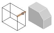
Creating Flat Representations of 3D Solid Objects
The MakeFlatSnapshot command creates a flat representation of 3D solid objects and Regions, projected to the drawing’s X-Y plane of the active Custom Coordinate System (CCS).
The 2D flattened representation can be inserted as a Block in the XY plane of the active CCS.
You can show or hide hidden lines and tangent edges in the flat representation. Additionally, you can change the color and style of the foreground and hidden lines.
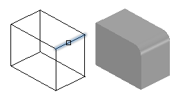
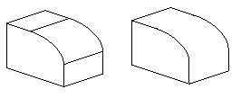
Tangent edges are visible transition edges between curved surfaces or curved and flat surfaces.
Example: Filleted edge with and without tangent edges.
To create a flat representation of 3D solid objects:
- In the graphics area, set up a view from which you want to make a flat snapshot. Use the Views command.
- Click Solids > Solid Editing > Make Flat Snapshot (or type MakeFlatSnapshot).
- In the dialog box, specify an option for Flat Snapshot Destination:
- Insert as Block: Inserts the flat representation as a Block in the graphics area.
- Replace existing Block: Replaces an existing Block in the drawing with the Block you created.
- Export to file: Saves the flat representation to an external drawing file.
- Optionally, select Show tangent edges to display tangent edges in the flat representation.
- Change the line color and style in the flat representation:
- Under Foreground lines, specify the color, the line style, and the line layer for the foreground lines.
- Under Hidden lines, select Show to display the hidden lines. You can modify the color, the line style, and specify the line layer for the hidden lines.
- Click OK.
Use the Explode command to break the Block representing the flattened view into its component entities. Exploding the Block lets you remove obscured lines or modify the LineStyle of hidden lines.
Access
Command: MakeFlatSnapshot
Menu: Solids > Solid Editing > Make Flat Snapshot
Ribbon: Insert > Block > Make Flat Snapshot
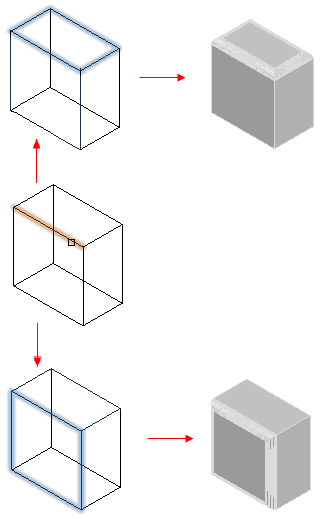
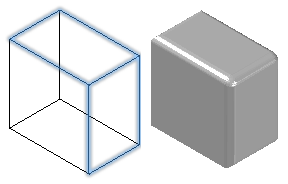
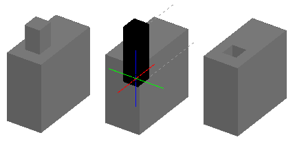
Modifying 3D Solids by Pushing and Pulling Geometry
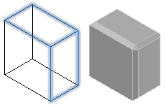
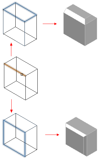
Use the PushPull command to extrude 2D entities into surfaces and to modify 3D solids.
The results vary based on the type of entity. If you push and pull linear entities such as lines or arcs, you create surfaces. For 3D solids, if you push and pull existing closed entities such as Circles and PolyLines, you modify the geometry of the 3D solid.
For 3D solids, you can simultaneously modify multiple closed entities.
To modify 3D solids by pushing and pulling geometry:
- Click Solids > Draw > Push and Pull (or type PushPull).
- In the graphics area, specify the entity to extrude and press Enter.
If you want to extrude more than one entity, specify the Multiple option.
You can click inside an entity (3D solid or area) or a face of a 3D solid and then drag it in or out. Thus you can create a hole or an extrusion.
- If you specified the Multiple option, specify other 3D solids and press Enter.
Note: You can specify multiple faces of the same 3D solid. The command will extrude all specified faces at once.
- Enter a value or click in the graphics area to specify the extrusion height. All selected entities will use the same extruding height.
The shape of the selected entities is extruded with the specified height.
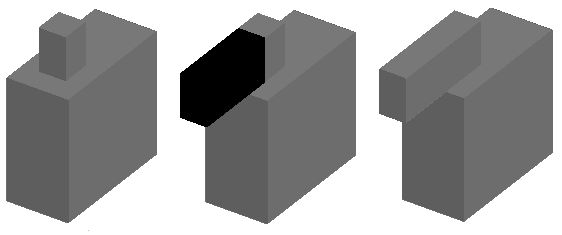
Examples:
Extruding a 3D solid by selecting a face and pulling it out.
Extruding a 3D solid by selecting a face and pushing it in.
Extruding two faces of a 3D solid.
Extruding a spline into a surface.
Access
Command: PushPull
Menu: Solids > Draw > Push and Pull
Ribbon: Home > Modeling > (Flyout) Push and Pull
Creating 2D Entities from 3D Models
This section discusses:
Creating Wireframe Geometry from Other Entities
The ConvertEdges command creates wireframe geometry from the edges of a specified 3D solid, surface, mesh, or region. You can extract one edge or all edges.
The resulting entities are lines, arcs, splines, or 3D polylines created along the edges of the selected entities.
For easier access, place the wireframe geometry on a separate layer. You can use it as reference for creating 3D solids, surfaces, and meshes.
To create wireframe geometry from entities:
- Click Solid Editing > Convert edges (or type ConvertEdges).
- In the graphics area, specify one or several of the following entities:
- 3D solids
- Surfaces
- Meshes
- Regions
- Press Enter.
2D entities such as lines, arcs, splines, or polylines are created along the edges of the specified entities.
To create wireframe geometry from faces and edges of other entities:
- Click Solid Editing > Convert edges (or type ConvertEdges).
- Specify an option:
- Edge. Specify edges on 3D solids, surfaces, or meshes.
- Face. Specify faces on 3D solids or meshes.
- Press Enter.
2D entities such as lines, arcs, splines, or polylines are created along the specified edges.
Access
Menu: Solid Editing > Convert edges
Command: ConvertEdges
Ribbon: Home > Solid Editing > (Flyout) Convert edges
Creating 2D Entities from Solid Faces and Surfaces
The OffsetEdges command creates 2D entities from the boundary of a 3D solid or surface. The resulting entities are closed polylines or splines located on the same plane as the specified boundary.
You can create the new entity inside or outside the specified boundary.
Note: The command ignores closed internal regions within the solid face boundary.
To create a 2D entity from a solid face:
- Click Solid Editing > Offset edges (or type OffsetEdges).
- In the graphics area, hover over the faces of a 3D solid or surface and click a face.
- Specify a point through which the offset entity passes through.
– or –
Specify an option:
- Corner. Specifies whether the boundary has Sharp or Round corners.
- Distance. Specify the offset distance from the boundary of the specified face. You can create the entity on one side of the boundary or on both sides.
- Repeat steps 2 and 3 to create 2D entities from other solid faces.
- Press Enter.
Access
Menu: Solid Editing > Offset edges
Command: OffsetEdges
Ribbon: Home > Solid Editing > (Flyout) Offset edges