Coordinates, OSNAPZ, UCS, ELEVATION and Related Issues
In all CAD systems (FLUID DESK BIM, AutoCAD and BricsCAD), there are important concepts users should be aware of when entering coordinates, picking points or modifying entities using grips or the STRETCH command. While with You can work in 2D using all FLUID DESK software modules, behind that is a full 3D model where elevation (and thus, the Z coordinate) matters a great deal.
For example, if You are moving objects using the MOVE command pick points that have different Z coordinates, You will end up moving those elements in that direction as well, weather You intended to or not. The solution to this problem is to set the OSNAPZ system variable to the value 1; that will force ANY picked point to have the same Z coordinate and not move (or disconnect) Your elements.
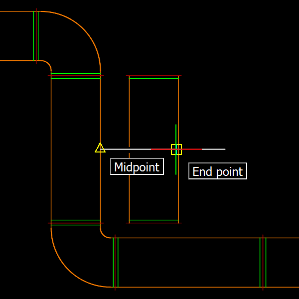
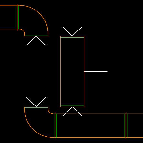
As seen above, if You do not pay attention to what coordinate and input modes are being used, the elevation of entities may be modified inadvertently, braking continuity of the installation. To avoid such cases, it is important learning to pay attention to how coordinates are determined. This issue becomes CRUCIAL while defining Cross Sections, as their definition can be very sensitive to the Z coordinates that are selected, both for defining the section base line points AND the direction! Again, setting OSNAPZ to the value 1 will usually – though not always, see below – resolve such situations.
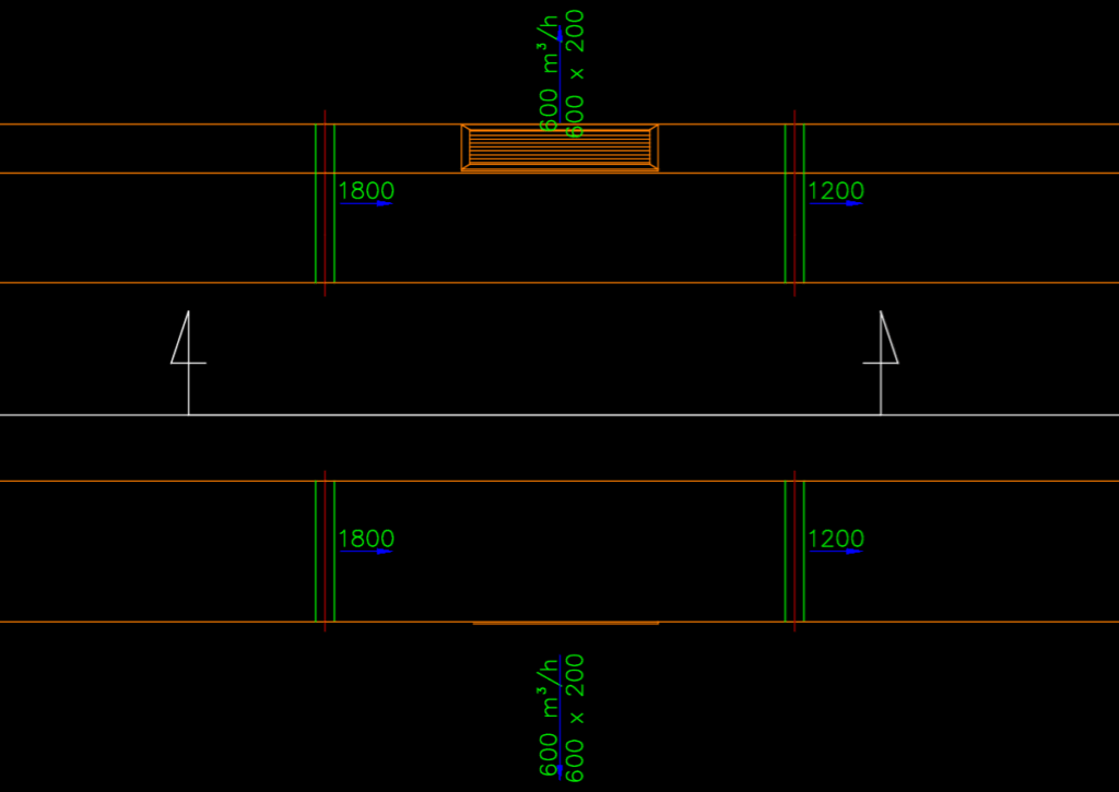
Additionally, there is a core concept at work here, that of Coordinate Systems; there are three possible types of coordinate systems commonly used on all of the above listed CAD platforms:
-
The Global Coordinate System (GCS) denotes the absolute coordinates that points are actually stored in, forming the basis for all of the other Coordinate Systems, This means that those are always defined and represented as transformations (offset, rotation, scale) relative to the GCS.
-
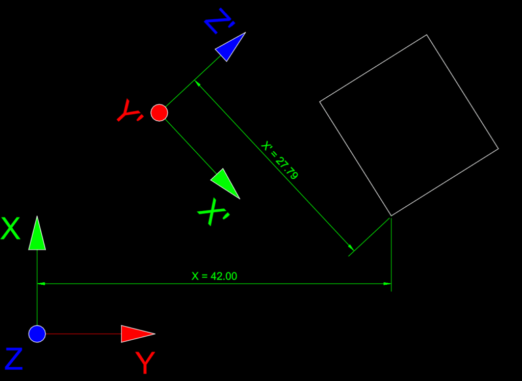
The User Coordinate System (UCS), also referred to as the Custom Coordinate System (CCS). These are user-defined coordinate systems used to aid the design process, and allows users to use custom-defined coordinate systems without having to actually transform all entities in the model. Usually defined by move, rotate and scale operations or by defining an origin and indicating the X, Y and Z vector directions. Once an UCS is in effect, all coordinates (*) displayed by the program will be relative to that system. It is not only possible to move the origin or rotate the Coordinate System around the Z axis, it is possible to re-define it completely so that, for instance, the global Y axis becomes the X’ axis and the global Z axis the Y’ axis (**). In that example, the global X axis will automatically take the place of the Z’ axis, as the base coordinate directions are still required to be mutually perpendicular.
-
Entity Coordinate Systems (ECS): each entity more complex than a LINE, POLYLINE or MESH will define its own coordinate system. This is because entities such as ELLIPSEs and BLOCKs define a unique plane, with an origin and rotations along each axis. When You select a BLOCK and edit it in-place (using REFEDIT, EDITBLOCK or just double-clicking on an INSERT entity), inside that BLOCK You will be working with that BLOCK’s own, local Coordinate System.
It is always possible to re-set the UCS to its default value, that is, setting it equal to the WCS (UCS command, WORLD sub-command) and You can name, save or load previously defined UCS settings using command line options (UCS command) or UCSMAN (CSSTYLE) to get a nice user interface. You also have the option to set the UCS to the currently active view (UCS command, VIEW sub-command) and the possibility of forcing the CAD system to make the view always follow the active UCS, however it was modified, by setting the UCSFOLLOW system variable to the value 1.
Another important factor to consider is the ELEVATION system variable. While the value of this variable, a decimal number, does not directly effect the UCS itself… nor the display of coordinate values, its value DOES effect any selected points. In particular, entities created and points picked will have their Z’ coordinate set to the value stored in that variable, so long as no reference entity is snapped when acquiring the point. Furthermore, using OSNAPZ (set to 1) will force ANY 3D snap point selected, INCLUDING those acquired from existing entities, to have their Z’ coordinate reset to the stored value.
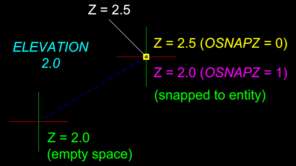
The ELEVATION value is thus understood as the offset of the ‘working plane’ from the UCS X’–Y’ plane, in the direction of the Z’ axis. It influences points being input but NOT the display of coordinates; for example, a LINE entity drawn with Z’ = 100.0 will display as 100.0, while moving the UCS by 100.0 in the Z’ direction will display the same line as having Z” = 0.0.
(*) There is an exception to this, elevation of FLM / Ventpack / Hydronicpack / Sanipack objects are always displayed in meters according to the WCS Z and not the UCS Z’ direction. We are working to design a mechanism to give our users more control over how elevation values are referenced and shown in our software modules for designing (mechanical / MEP) systems for buildings.
(**) The convention for coordinates used is as follows. The X, Y, and Z directions denote WCS coordinates: X = (1, 0, 0), Y = (0, 1, 0) and Z = (0, 0, 1). The symbols X’, Y’ and Z’ are used to denote UCS coordinates; for example, if I move the UCS by 100 in the X direction and then rotate it 90°, I would have the point (X, Y, Z) = (100, 50, 0) correspond to the point (X’, Y’, Z’) = (50, 0, 0). Similarly, if I modify the UCS again by moving it 100 in the Y’ direction, I could denote the resulting coordinates as (X”, Y”, Z”) = (-50, 0, 0).
