When using FLM, Ventpack, Hydronicpack and Sanipack functions, You may encounter errors such as incorrect geometry being created, functions failing randomly or operations taking much too long to complete. Here are some basic tips and tricks how You can avoid such typical problems.
-
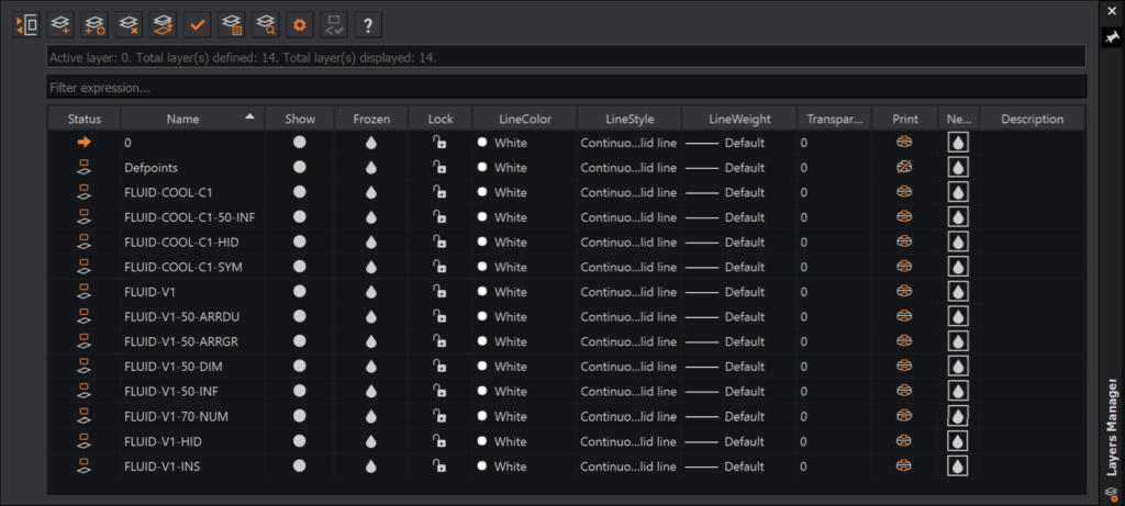
Keep the layers below unlocked, thawed (unfrozen) and visible at all times:
-
The current layer
-
The built-in layer “0”
-
The built-in layer “Defpoints”
-
-
You should also show, unfreeze an unlock any “FLUID-*” layers that You are actually working on, e.g. that contain objects that You will modify or that should be updated as a result of any changes.
-
FLUID-{System Name} (Elements in each system)
-
FLUID-{System Name}–INS (Insulation / Lining lines)
-
FLUID-{System Name}-SYM (Symmetrical / Axis lines)
-
FLUID-{System Name}-HID (Hidden lines)
-
FLUID-{System Name}-COL (Collision lines)
-
FLUID-{System Name}–{Size}–NUM (Numbering)
-
FLUID-{System Name}–{Size}-DIM (Dimensions)
-
FLUID-{System Name}–{Size}-INF (Info Frames)
-
FLUID-{System Name}–{Size}–ARRDU (Duct Arrows)
-
FLUID-{System Name}–{Size}–ARRGR (Endpoint Arrows)
-
FLUID-{System Name}–{Size}–RCONN (Remote Connections)
-
FLUID-COOL-{System Name} (Elements in each system)
-
FLUID-COOL-{System Name}–INS (Insulation / Lining lines)
-
FLUID-COOL-{System Name}-SYM (Symmetrical / Axis lines)
-
FLUID-COOL-{System Name}-HID (Hidden lines)
-
FLUID-COOL-{System Name}-COL (Collision lines)
-
FLUID-COOL-{System Name}–{Size}-INF (Info Frames)
-
FLUID-COOL-{System Name}–{Size}–RCONN (Remote Connections)
-
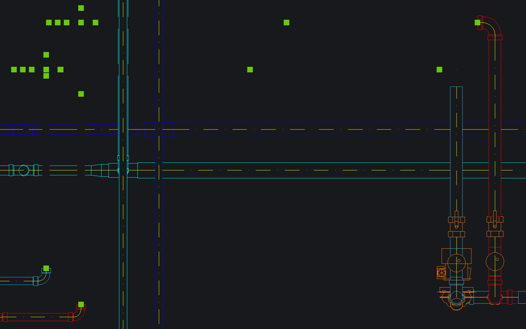
If You violate the above rule and continue designing systems, modifying elements, placing or moving labels, numbers and dimensions… or perform any kind of calculations with layers invisible, frozen or locked, you may encounter various error conditions that can include corrupt or missing geometry:
-
To fix such problems, turn on, unfreeze and unlock all relevant layers,
-
Select parts of the system (and surrounding elements) having incorrect geometry,
-
Run the Modify Element function and press OK without changing anything; this will update and re-generate all associated geometry, correcting any issues having resulted from the mistake.
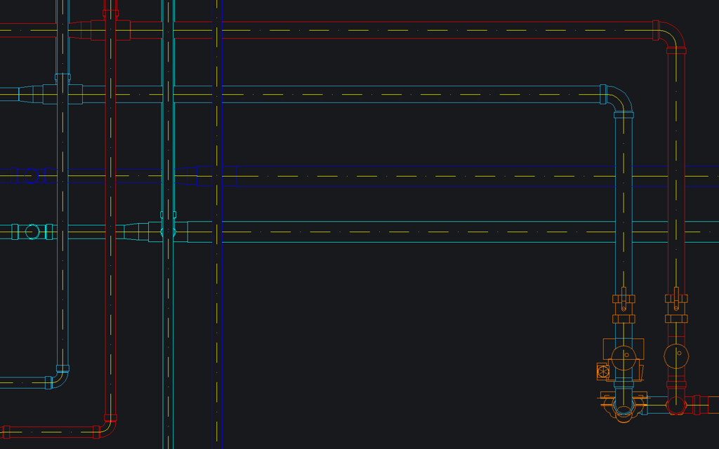
You should also be aware that elements will have missing geometry if they are hidden by elements above them… and if those elements are on a layer that is not visible, it will not be obvious why.
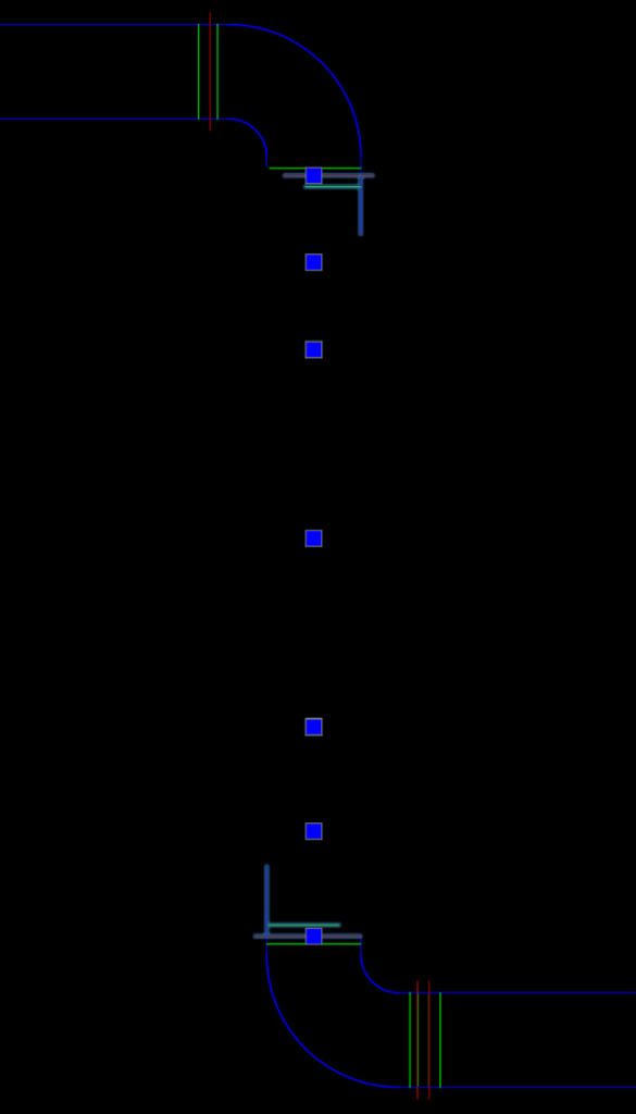
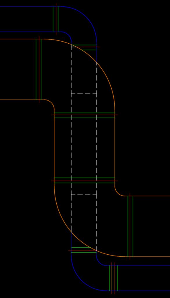
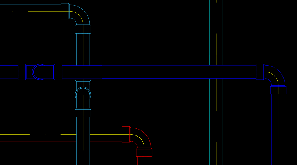
You can also see geometry / HLR (Hidden Line Removal) errors when Your drawing is too far from the Origin. While such situation may be necessitated by the architectural drawings being created using GPS Coordinates, You will need to take some steps to avoid or work around such situations.
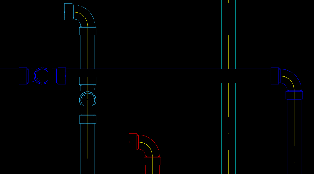
-
You can move the model closer to the Origin – (0, 0, 0) in WCS (World Coordinate System) coordinates, and then re-define Your UCS (User Coordinate System) such that the CAD system displays the desired GPS values for all point coordinate values.
If You are having trouble with operations such as Continuous Drawing, Pipe Drawing, placing, attaching or modifying elements taking longer than normal, that can often be caused by the Automatic Airflow and Pressure Loss Calculations running in the background.
-
You can disable that behavior in the Ventpack / Hydronicpack settings:
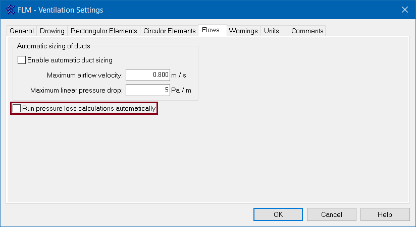
Do not worry: when You run the Pressure Loss Analysis commands, all necessary calculations will be updated correctly; the only draw-back to turning off the Automatic calculations is that You will not have up-to-date values displayed on Your drawing until You will have ran calculations Yourself.
