
Introduction
This chapter describes how to:
- Create and Insert Blocks. Blocks bind entities together to form a single entity. You can insert internal Blocks and external drawings as Blocks into drawings.
- Link BlockAttributes to Blocks. BlockAttributes are entities that let you link labels or variable text information to Blocks.
- Group Entities. EntityGroups are collections of entities (similar to Blocks) that are treated as one. Unlike Blocks, EntityGroups are not designed for repetitive insertions.
- Use References. References attach a separate drawing to the current drawing.
- Edit Components. In-place editing lets you modify the definition of referenced Blocks or externally referenced drawings.
Defining and Inserting Blocks
Blocks bind entities together to form a single entity.
You can insert internal Blocks and external drawings as Blocks into drawings.
This section discusses:
Defining Blocks
A Block is a collection of entities bound together as a single entity. After you create a Block, you can insert it whenever you need it in a drawing.
When you use the MakeBlock command, the Block is recognized in the current drawing only. The ExportDrawing command lets you write a Block to an external drawing file for use in any drawing.
To define Blocks:
- Click Draw > Block > Define (or type MakeBlock).
- In the dialog box, for Name, type a name for the Block, or select an existing Block to overwrite a Block. Names may have up to 255 characters, and may contain letters, numbers, blank spaces, and special characters such as $, #, _. The name is case-sensitive.
- For Description, type a Block description.
- Under Settings, select options:
- Annotative scaling. Specifies whether annotative scaling is applied when you insert the Block.
-
Orient block to match scale. Specifies that in Viewports Block orientation matches layout Sheet orientation.
This option is available only if you selected Annotative Scaling for Block insertions.
- Apply uniform scale. Restricts the Block to a uniform scale when inserting the Block. Otherwise you can specify different X, Y, and Z scaling factors when inserting the Block.
- Allow block to explode. Lets the Block explode on insertion.
- Units. Lets you select different units from those in the current drawing.
- Attach Hyperlink. Lets you specify a hyperlink for the Block.
- Under Base Point, set the base point that serves as the insertion point when inserting the Block. It is also the base point for changing the scale and serves as a rotation point during the insertion.
Do one of the following:
- Click Select in graphics area
 to specify the base point of the Block in the drawing.
 - For X, Y, and Z, type coordinate values.
- Click Select in graphics area
- Under Block entities:
- Click Select in graphics area
 to specify the entities to form the Block.
 - Set options:
- Preserve as separate entities. Leaves the source entities as they are.
- Convert to block. Replaces the source entities with a Reference of the Block definition.
- Remove from drawing. Removes the source entities from the drawing.
- Click Select in graphics area
- Click OK.
If you selected an existing Block in Name, you are asked to redefine the Block.
Access
Command: MakeBlock
Menu: Draw > Block > Define
Ribbon: Insert > Block > Define 
Tool Palettes: Draw > Make Block
Inserting Blocks
You can insert internal Blocks and external drawings as Blocks into drawings.
Inserting a Block in the drawing creates a Block reference.
You can insert:
- Blocks defined in the active drawing
- Blocks defined in external drawing files
Tip: You can group Blocks in block libraries.
The following tools and methods let you insert Blocks:
- Block Library palette
- Block Structure palette
- Design Resources palette
- Drag and drop drawings from a folder
To insert Blocks:
- Click Insert > Block (or type InsertBlock).
- In the dialog box, in Name, select a Block. Click Browse to locate an external drawing.
The preview area displays the selected Block.
Note: The sign in the lower right corner of the Preview area identifies the Block:
 Dynamic Block
CB CustomBlock
- Under Position, for X, Y, and Z, specify coordinate values, or select Specify later to specify the insertion point on screen after the dialog box closes.
- Under Scale:
- For X, Y, and Z, specify the scale factor for each axis.
– or –
- Click Specify later to define the Block size during insertion. Specify the Corner option, then define the opposite point of the rectangle where the Block is to fit.
– or –
- Click Apply uniform scale, and for X, specify a scale factor. A scale factor of:
- 1: Inserts the Block at its original size.
- Less than 1: Reduces the size to the percentage of the original size specified by the factor.
- Greater than 1: Increases the size.
- For X, Y, and Z, specify the scale factor for each axis.
- Under Rotate, for Angle, specify a value or select Specify later to set the rotation angle in the graphics area during insertion.
- Under Block UnitSystem:
- You cannot edit the Units or Scale. If Scale is unequal to 1.0, then the drawing units differ from the Block units.
- Select Explode Block to explode the Block into its component entities. A Block loses its characteristics when exploded. You can explode uniform scaled Blocks only.
- Click OK.
The Block appears attached to the mouse cursor.
- Click a point to place the Block.
Access
Command: InsertBlock
Menu: Insert > Block
Ribbon: Insert > Block > Insert
Tool Palettes: Draw > Insert Block
Inserting a Block in a Rectangular Pattern
Use the InsertBlockN command to insert multiple copies of a Block or external drawing in a pattern, arranged in rows and columns.
To insert multiple copies of a Block or drawing in a rectangular pattern:
- Type InsertBlockN at the command prompt.
- Type the name of the Block or drawing to insert, or specify the ? option to view the Blocks defined in the current drawing.
- Type the base point for the insertion.
- Type the X scale or click in the graphics area to set the opposite corner. Press Enter to confirm 1.0 as scale factor.
- Type the Y scale. Press Enter to use the value equal to the X scale factor.
- Type a rotation angle.
- Type the number of rows to insert.
- Type the number of columns to insert.
- Type the distance between the rows and the distance between the columns.
- – or –
- Specify a unit cell in the graphics area by two opposite points or type X and Y values.
- The Block or external drawing appears in a rectangular pattern.
 You cannot explode Blocks inserted with the InsertBlockN command. However, you can edit uniformly scaled Blocks inserted with the InsertBlockN command using the EditComponent command.
Access
Command: InsertBlockN
Modifying the Base Point of a Block
Use the RedefineBasePoint command to set a new insertion base point for all instances of a Block.
Another way to modify the base point of a Block is using the EditBasePoint command in Component editing mode.
Note: For nested Blocks, you can modify only the base point of the parent Block.
To modify the base point of a block:
- In the graphics area, select a Block instance.
- Do one of the following:
- Right-click and click Redefine Block Base Point.
- Type RedefineBasePoint.
Rubberband appears between the current base point of the Block and the pointer.
- Specify the new base point.
All Block instances in the drawing are updated.
Access
Command: RedefineBasePoint
Saving Blocks to File
You can write entities, a Block, or an entire drawing to a new drawing file.
You can save a Block or entities as a separate drawing file that you can insert into other drawings.
The ExportDrawing command is similar to the MakeBlock command, but is mainly used to export Blocks, not to define them in the drawing.
To save Blocks to file:
- Click File > Export > Export Drawing (or type ExportDrawing).
- In the dialog box, under Source, select a source to write to file:
- Block. Lets you select an existing Block in the drawing to write to file.
- All entities. Writes the entire drawing to file.
- Selected entities. Writes the entities you select to file.
- Under Block UnitSystem, in UnitSystem, select the units to use for automatic scaling when the file is inserted in a drawing that uses different units (see the UnitSystem command, Block units format option).
- Under Entities:
- Click Specify entities and select entities in the graphics area to make up the Block.
- Select an option:
- Convert to Block. Replaces the source entities with a Reference of the Block definition.
- Do not convert to Block. Leaves the source entities in the drawing as they are.
- Delete. Removes the source entities from the drawing.
- Click Specify entities
- Under Base point, for X, Y, and Z, type coordinate values or click Specify in graphics area to specify an insertion base point in the graphics area.
The insertion base point is also used as the base for changing the Block’s scale and rotation.
- Under Destination, select a file name and path where the Block or entities are saved, or click Browse to locate a destination folder and type a File name.
- Click OK.
Access
Command: ExportDrawing
Menu: File > Export > Export Drawing
Ribbon: Insert > Block Definition > Export Drawing
Working with BlockAttributes
You can attach attributes to Blocks to provide information about the Block. For instance, if you use a Block to represent a stove, you might use attributes such as symbol number, room number, and comment (gas or electrical, for example).
The following topics help you work with BlockAttributes:
- Defining BlockAttributes
- Editing BlockAttribute Definitions
- Editing BlockAttributes
- Editing BlockAttribute Values In-place
- Using the Multiline BlockAttribute Formatting Pop-up Toolbar
- Displaying BlockAttributes
- Updating BlockAttributes
- Extracting BlockAttributes to a Text File
- Creating Template Files for BlockAttribute Extractions
- Exporting BlockAttributes Values
- Exporting BlockAttribute Values Including Block Positions
Defining BlockAttributes
BlockAttribute definitions let you attach variable or constant text to Blocks. When you insert a Block containing BlockAttributes, you are prompted to specify values for each BlockAttribute (unless the value is defined with a constant value).
You can define BlockAttributes as singleline or multiline objects.
You can edit BlockAttributes of Block references later with the EditBlockAttribute command. You can edit the name, request, and value with the EditAnnotation command.
To define BlockAttributes:
- Do one of the following:
- On the ribbon, click Insert > Block Definition > Define Block Attribute.
- On the menu, click Draw > Block > Define Block Attributes.
- Type MakeBlockAttribute.
- In the dialog box, under Display, type options.
- Name. Defines the BlockAttribute name. It may have any number of characters. Blanks are not allowed.
- Caption. Displays text at the command window during Block insertion. It may have up to 256 characters. Characters such as blanks, underscores and dollar signs are allowed. You may omit the request if the Block uses a constant BlockAttribute value. For example, when you specify “Enter norm term” as a request, a typical answer would be “Schedule 40 steel pipe” as the value.
-
Default value. Displays the visible component of the BlockAttribute in the drawing. It may have up to 256 characters and may be a constant or variable.
Characters such as blanks, underscores and dollar signs are allowed.
- If you define a singleline BlockAttribute, you can apply Fields in default value specifications.
Click Field
 to insert a Field.
 - If you define a multiline BlockAttribute, you cannot specify a default value in the input field.
Click Open Multiline Editor
 to define default text in the graphics area using the Multiline BlockAttribute Formatting pop-up toolbar. The editor settings (editing in-place or in a dialog box) specified for Notes with the NoteOptions command also apply for multiline BlockAttribute definitions.
- If you define a singleline BlockAttribute, you can apply Fields in default value specifications.
- Under Text settings, set:
- TextStyle. Sets the TextStyle. You can create new TextStyles with the TextStyle command.
- Justification. Sets the position and alignment of the BlockAttribute text in relation to the insertion point.
- Annotative scaling. Specifies whether annotative scaling is applied when inserting Blocks with the BlockAttribute you define. If the Block that contains the BlockAttribute is defined as an annotative entity, the BlockAttribute follows the Block orientation.
-
Height. Defines the text size. To specify the text height on screen, click Select in graphics area
 .
. -
Rotation. Specifies the BlockAttribute insertion angle. Type a value between 0° and 360°. To specify the rotation on screen, click Select in graphics area
 .
. -
Width. Defines for multiline BlockAttributes the maximum width of text lines before wrapping to the next line. Set the value to 0.00 to have no restriction on the text line length. To specify the width on screen, click Select in graphics area . This option is available only if you selected the Multiline option (see below).
- Under Insertion point:
Do one of the following:
- Type X, Y, and Z coordinate values.
- Select Specify later to specify the insertion point on screen after the dialog box closes.
- Click Select in graphics area to immediately specify the insertion point.
- Under Behavior, select:
- Fixed. Allows you to switch between constant and variable BlockAttribute values. When selected, the text in Default value is a constant BlockAttribute value in the drawing. You cannot insert variable data. When cleared, you are prompted to insert a variable BlockAttribute value.
- Hidden. Controls the visibility of the BlockAttribute value in Block references. When selected, the value does not display during insertion in the drawing. Use this if the BlockAttribute contains information to analyze later that does not have to be displayed on the drawing. This option is also helpful when there are so many BlockAttributes that the drawing is unclear and confusing. To temporarily display hidden BlockAttributes use the DisplayBlockAttributes command.
- Predefined. Lets you create BlockAttributes that accept their default values. When selected, values are not requested. The option lets you edit values after insertion with the editing commands.
- Validate. Prompts you for verification that the BlockAttribute value is correct when inserting a Block.
- Multilines. Specifies whether the BlockAttribute is singleline or multiline. For multiline BlockAttributes, specify the maximum width of text lines (see the Width option above). You cannot specify a default value for multiline BlockAttributes (see the Default value option above).
- Set additional options:
- Lock in Block. Determines whether the BlockAttribute within the Block reference is locked. When unlocked, you can move the BlockAttribute with EntityGrips.
-
Position below last definition. Lets you align the current BlockAttribute definition below the previous one.
This option is available during creation of BlockAttribute definitions only if the previous definition was a singleline BlockAttribute definition.
Access
Command: MakeBlockAttribute
Menu: Draw > Block > Define Block Attributes
Ribbon: Insert > Block Definition > Define Block Attribute
Tool Palettes: Draw > Define Block Attribute
Editing BlockAttribute Definitions
You can modify parameters of the selected BlockAttribute definition and the location, text options, and attribute modes.
To edit BlockAttribute definitions:
- Type EditBlockAttributeDefinition.
- In the graphics area, select a BlockAttribute definition.
- In the Block Attribute Definition dialog box, set options.
The command makes it easy to create several similar BlockAttribute definitions. You can copy a master BlockAttribute definition, then edit the Name and Caption parameters in the Block Attribute Definition dialog box.
Access
Command: EditBlockAttributeDefinition
Editing BlockAttributes
Use the EditBlockAttribute command to modify the BlockAttribute values of inserted Blocks.
To modify BlockAttribute properties such as the insertion point, height, and TextStyle, use the -EditBlockAttribute command.
You cannot edit BlockAttribute values on locked Layers.
To edit BlockAttributes:
- Type EditBlockAttribute, then select a Block reference in the graphics area.
- In the dialog box, select an item in Value. You cannot edit BlockAttribute values on locked Layers.
- Edit the value:
- If the BlockAttribute is a single-line BlockAttribute, type a new Value.
- If the BlockAttribute is a multiline BlockAttribute, click Open Multiline Editor to edit the text in the graphics area using the Multiline BlockAttribute Formatting pop-up toolbar. The editor settings (editing in-place or in a dialog box) specified for Notes with the NoteOptions command also apply for multiline BlockAttributes.
- Repeat steps 3 and 4 as needed for other BlockAttributes.
- Click OK.
Note: Assuming that a BlockAttribute is not defined as locked in Block, you can modify the insertion point of a BlockAttribute by selecting its EntityGrip and drag it to a new location.
Access
Command: EditBlockAttribute
Applying Extended Editing of BlockAttributes
Use the EditXBlockAttribute command to modify the BlockAttribute values and properties of inserted Blocks.
Property changes include Layer, TextStyle, and other settings.
You cannot edit BlockAttribute values on locked Layers.
To apply extended editing of BlockAttributes:
- Do one of the following:
- Double-click a Block with BlockAttributes.
- On the ribbon, click Insert > Block > Attributes > Edit Single Attribute.
- Type EditXBlockAttribute, then select a Block reference with BlockAttributes in the graphics area.
- In the dialog box, select an item in Value.
- Edit the value:
- If the BlockAttribute is a singleline BlockAttribute, type a new Value.
- If the BlockAttribute is a multiline BlockAttribute, click Open Multiline Editor to edit the text in the graphics area using the Multiline BlockAttribute Formatting pop-up toolbar.
Note: The editor settings (editing in-place or in a dialog box) specified for Notes with the NoteOptions command also apply for multiline BlockAttributes.
- Select Change attribute value to all instances to overwrite the value of the BlockAttribute in all instances of the Block in the drawing. Use caution with this option as it potentially replaces all previous BlockAttribute edits.
- Edit properties:
- Under Properties, change the Layer, LineStyle, LineColor, LineWeight, and PrintStyle of the BlockAttribute.
Note: LineStyles and LineWeights become visible only if the TextStyle of the BlockAttribute is based on a SHX font, not a TrueType font.
- Under Text options, modify the TextStyle, Justification, Spacing, Height, Rotation, and Width of the BlockAttribute text.
If the TextStyle supports the corresponding options, specify whether to generate the text Backwards or Upside down, and whether the text uses Annotative scaling.
- Under Apply changes select To all instances, to update the properties and text settings for all instances of Blocks in the drawing.
Click Hide/Show Properties
 to collapse or expand the properties area of the dialog box.
 - Under Properties, change the Layer, LineStyle, LineColor, LineWeight, and PrintStyle of the BlockAttribute.
- Click Apply for intermediate updates of your changes.
- Repeat steps 2 through 5 for other BlockAttributes.
- Click OK
 .
.
Note: You can modify the insertion point of a BlockAttribute by selecting its EGrip and dragging it to a new location (as long as the BlockAttribute is not locked).
Access
Command: EditXBlockAttribute
Ribbon: Insert > Block > Attributes > Edit Single Attribute
Tool Palettes: Modify > Edit Single Attribute
Editing BlockAttribute Values In-place
Use the EditIpBlockAttribute command to edit the values of BlockAttributes in-place.
To edit BlockAttribute values:
- Type EditIpBlockAttribute at the command prompt.
- In the graphics area, specify a BlockAttribute.
- Edit the BlockAttribute value in place:
- If the selected entity is a singleline BlockAttribute, the SimpleNote Formatting pop-up toolbar displays.
- If the selected entity is a multiline BlockAttribute, the Multiline BlockAttribute Formatting pop-up toolbar displays.
- Click OK
 .
.
Access
Command: EditIpBlockAttribute
Using the Multiline BlockAttribute Formatting Pop-up Toolbar
Use the Multiline BlockAttribute Formatting pop-up toolbar to edit and format multiline BlockAttributes and multiline BlockAttributes definitions.
To open the Multiline BlockAttribute Formatting pop-up toolbar:
- When you type a multiline BlockAttribute definition or a multiline BlockAttribute, right-click and click Editor Settings > Show Toolbar.
To format BlockAttributes using the Multiline BlockAttribute Formatting pop-up toolbar:
- As you type and edit, specify toolbar options as needed:
-
Undo
 . Removes the previous text editing or formatting.
 -
Redo
 . Restores the state prior to issuing Undo.
 -
Underline
 . Specifies underline formatting for subsequent or selected text.
 -
Overline
 . Specifies overline formatting for subsequent or selected text.
 - Ruler. Displays a ruler at the top of the text box.
-
Insert Field
 . Inserts a Field at the cursor position.
 -
Other Options
 . From the menu, select an option:
- Find and Replace. Lets you search for text strings and replace text strings.
- AutoCAPS. Creates new text with uppercase characters. To alter the case of existing text, highlight the text, then right-click, and click Change Case. AutoCAPS does not affect existing text.
-
Editor Settings. Specify options:
- Always display as WYSIWYG. Controls text display when you edit text. When selected, text is displayed with the size and insertion angle as defined. When cleared, text that is very small, very large, or rotated and difficult to read is displayed at a legible size and horizontally oriented so you can read it easily.
- Show Toolbar. Shows or hides the Note Formatting pop-up toolbar.
- Opaque Background. Shows or hides opaque background.
- Show Ruler. Shows or hides the ruler.
- Text Highlight Color. Specifies the background color when text is selected.
- Background Mask. Specifies an opaque background color behind the multiline BlockAttribute.
-
Help
 . Displays this help topic.
 -
OK . Finishes multiline BlockAttribute editing.
Note: Use the NoteOptions command to specify whether you want to edit Notes in place or in a dialog box. The settings for Notes apply also for multiline BlockAttribute definitions.
To use shortcut menu options:
- As you type and edit, right-click and select options as needed:
- Text Import. Inserts text from an ASCII text file (.txt) or Rich Text Format file (.rtf).
- Change Case. Changes selected text to Uppercase or Lowercase.
- Remove Formatting. Lets you Remove Character Formatting, Remove Paragraph Formatting, or Remove All Formatting from the selected text.
- Paste Special. Lets you Paste without Character Formatting, Paste without Paragraph Formatting, or Paste without Any Formatting from the clipboard. To paste text from the clipboard with formatting, click Paste on the shortcut menu.
Note: Other options on the shortcut menu are available on the Multiline BlockAttribute Formatting pop-up toolbar, many of them are available on the Other Options menu (see above).
Displaying BlockAttributes
You can control the display of BlockAttributes in a drawing.
To display BlockAttributes:
- Do one of the following:
- On the ribbon, click Insert > Block Definition > BlockAttributes Display Mode.
- On the menu, click View > Display > Block Attribute.
- Type DisplayBlockAttributes.
- Specify an option:
- Normal: Displays based on the BlockAttribute definition.
- On: Displays all BlockAttributes.
- Off: Hides all BlockAttributes.
Access
Command: DisplayBlockAttributes
Menu: View > Display > Block Attribute
Ribbon: Insert > Block Definition > BlockAttributes Display Mode
Updating BlockAttributes
Use the UpdateBlockAttributes command to update all instances of Blocks with new or modified BlockAttributes.
You can change or add BlockAttributes to an existing Block definition by redefining the Block with the MakeBlock command.
Another way to modify the definition and properties of BlockAttributes is with the EditComponent command.
Both commands update the geometry of all instances of the redefined Block, but they do not automatically update the BlockAttributes that have been modified.
To update BlockAttributes:
- Type UpdateBlockAttributes at the command prompt.
- Specify an option:
- ? to list: View a list of all Blocks with BlockAttributes defined in the drawing.
- Name: Specify the name of the Block to update.
- Select: Specify a Block with BlockAttributes in the grapfics area, then confirm the update.
If you specified a Block, all BlockAttributes in the drawing are rebuilt.
Access
Command: UpdateBlockAttributes
Managing BlockAttribute Properties and Settings
Use the BlockAttributeManager command to edit the BlockAttribute properties and settings in Block definitions.
You can also:
- Change the order in which you are prompted for BlockAttribute values when you insert a Block
- Synchronize all instances of Blocks based on settings in the Block Attribute Manager
- Delete BlockAttributes from Blocks
To manage BlockAttribute properties and settings:
- Do one of the following:
- On the ribbon, click Insert > Block > Attributes > Attributes Manager.
- On the menu, click Modify > Entity > BlockAttribute Manager.
- Type BlockAttributeManager.
- In the dialog box:
- Select a Block name from the drop-down list.
– or –
- Click Specify Block to specify a Block in the graphics area.
The BlockAttributes list displays the names of all BlockAttributes contained in the specified Block.
One of the BlockAttributes is marked as activated in the list. Click a list item to select another BlockAttribute.
Click Show Display Options
to expand the dialog box to show display options for the BlockAttributes list. - Select a Block name from the drop-down list.
- Set preferences for changes in the drawing, apply functions to the selected BlockAttribute, and set display options for the list:
- Apply changes to existing references. Updates all existing instances in the drawing with the changes specified for the selected BlockAttribute. If cleared, only new instances of the selected Block are updated.
- Emphasize duplicate tags. Blocks may have several BlockAttributes with the same name. When selected, duplicate BlockAttribute names are highlighted in the list.
- Sync. Updates the BlockAttributes in all instances of the selected Block with the defined settings. This does not affect any values assigned to BlockAttributes of Block instances in the drawing.
- Move Up / Move Down. Moves the selected BlockAttribute up and down in prompt sequence.
- Edit. Displays a dialog box which lets you change the selected BlockAttribute in all aspects (see below).
- Delete. Removes the selected BlockAttribute from the Block definition. You cannot delete a BlockAttribute that is the only one in the selected Block.
-
Display Options. Determines the items to show in columns in the BlockAttributes list.
- Select or clear the characteristics and properties such as Caption, Value, Behavior, text settings, and other properties.
- Select All. Displays all characteristics of the BlockAttributes.
- Remove All. Clears the list (only the BlockAttribute names appear in the list).
- Click Edit to edit the characteristics and properties of the selected BlockAttribute.
Note: You can also double-click a row in the BlockAttributes list to open the Edit BlockAttribute Options dialog box for the specified BlockAttribute.
- In the dialog box, select a tab and edit:
-
BlockAttribute Settings tab. Lets you modify the basic BlockAttribute characteristics: Name, Caption, Value, and Behavior settings.
The Behavior characteristics are the same as those that you specify when defining BlockAttributes (see Defining BlockAttributes):
- Fixed. Allows you to switch between constant and variable BlockAttribute values. When selected, the text in Default value is a constant BlockAttribute value in the drawing. You cannot insert variable data. When cleared, you are prompted to insert a variable BlockAttribute value.
- Hidden. Controls the visibility of the BlockAttribute value in Block references. When selected, the value does not display during insertion in the drawing. Use this if the BlockAttribute contains information to analyze later that does not have to be displayed on the drawing. This option is also helpful when there are so many BlockAttributes that the drawing is unclear and confusing. To temporarily display hidden BlockAttributes use the DisplayBlockAttributes command.
- Predefined. Lets you create BlockAttributes that accept their default values. When selected, values are not requested. The option lets you edit values after insertion with the editing commands.
- Validate. Prompts you for verification that the BlockAttribute value is correct when inserting a Block.
- Multilines. Specifies whether the BlockAttribute is singleline or multiline. For multiline BlockAttributes, specify the maximum width of text lines (see the Width option above). You cannot specify a default value for multiline BlockAttributes (see the Default value option above).
- Text Settings tab. Lets you modify text properties of the BlockAttribute such as TextStyle, justification, spacing, inclination angle, text height, and rotation angle.
- Properties tab. Lets you modify general properties of the BlockAttribute such as Layer, LineStyle, LineColor, LineWeight, and PrintStyle.
-
BlockAttribute Settings tab. Lets you modify the basic BlockAttribute characteristics: Name, Caption, Value, and Behavior settings.
- Click OK to close the Edit Options dialog box.
- Click Apply to apply the changes.
The dialog box stays open to allow changes for other BlockAttributes.
– or –
Click OK.
Access
Command: BlockAttributeManager
Menu: Modify > Entity > BlockAttribute Manager
Ribbon: Insert > Block > Attributes > Attributes Manager
Tool Palettes: Modify > Attributes Manager
Extracting BlockAttributes to a Text File
The ExtractBlockAttribute command lets you extract BlockAttribute values to text files of various formats.
Template files define the data to extract.
You can examine the extracted data using spreadsheet software or other applications.
To extract BlockAttributes to a text file:
- Type ExtractBlockAttribute at the command prompt.
- In the dialog box, for Template, type a template name to define the data to extract. Click
 to browse for a file.
See Creating Template Files for BlockAttribute Extractions for information about the file syntax.
- Click Select Entities to specify the entities for extracting BlockAttribute data.
The dialog box closes temporarily.
- In the graphics area, select Blocks with BlockAttributes and press Enter.
- In the dialog box, for Output, type the location and name of the output file. Click
 to select a file name.
 - In Format, select the file format to use when writing the BlockAttributes information:
- Comma Delimited File (CDF). Commas separate the fields of each BlockAttribute record. Strings are enclosed by single quotation marks.
- Space Delimited File (SDF). Spaces separate the fields of each BlockAttribute record. Strings are enclosed by single quotation marks.
- Click OK.
Creating Template Files for BlockAttribute Extractions
Template files for BlockAttribute extractions define the data fields to extract and control the format in which they appear.
Use an ASCII text editor to create a template file for BlockAttribute Extractions.
Each line in the template file:
- Specifies the BlockAttributes and the Block properties to extract.
- Must use a specific syntax described below.
- Becomes a column in the resulting output file (see example).
You must include at least one BlockAttribute name in a template file.
File Syntax
Each line in the template file uses the following syntax:
field_name [space(s)] output_format
Valid field names are shown in the Extraction Field Names table below.
One or more spaces separate field_name and output_format. Use spaces, no tabs. End each line by pressing Enter, including the last line.
The output format uses the following syntax:
Twwwppp
The data type (T) can be:
| C | Indicates a character string field. |
| N | Indicates a numeric field. |
The next two portions of the output format use three digits:
| www | Width | Specifies the width of the field as a number of characters. |
| ppp | Precision | Specifies the number of decimal places for numeric fields. For character integer fields, specify 000. |
For example,
- Use N006002 for a numeric value up to 999.99. N stands for numeric data, 006 means that there is space for up to six digits, including the decimal point, and 002 specifies the precision of two decimal places.
- Use C025000 for a string field with a maximum length of 25 characters. Always specify 000 as the last three format digits for character fields.
Table: Extraction Field Names
You can extract:
- The value of BlockAttributes of Blocks inserted into the drawing.
- Predefined properties of the Block to which the BlockAttribute belongs.
Use the following extraction field names and format specifications to extract relevant data:
| Field Name | Format | Extracts |
|---|---|---|
| BlockAttribute name | Cwww000, or Nwwwppp | BlockAttribute value |
| BL:NAME | Cwww000 | Block name |
| BL:X | Nwwwppp | X coordinate of Block insertion point |
| BL:Y | Nwwwppp | Y coordinate of Block insertion point |
| BL:Z | Nwwwppp | Z coordinate of Block insertion point |
| BL:ORIENT | Nwwwppp | Block rotation angle |
| BL:XSCALE | Nwwwppp | X scale factor for Block |
| BL:YSCALE | Nwwwppp | Y scale factor for Block |
| BL:ZSCALE | Nwwwppp | Z scale factor for Block |
| BL:XEXTRUDE | Nwwwppp | Block extrusion in X direction |
| BL:YEXTRUDE | Nwwwppp | Block extrusion in Y direction |
| BL:ZEXTRUDE | Nwwwppp | Block extrusion in Z direction |
| BL:LAYER | Cwww000 | Block insertion Layer name |
| BL:HANDLE | Cwww000 | Block handle |
| BL:NUMBER | Nwww000 | Block counter |
| BL:LEVEL | Nwww000 | Block nesting level |
Example
Template file:
BUILDINGTYPE C030000
ZONENAME C025000
ACTIVITY C020000
HVACSYSTEM C025000
AREA N006002
HEIGHT N004002
BL:NAME C012000
BL:NUMBER N002000
Output file (.cdf format):
‘Workshops/maintenance depot’,’Z0/09 Staff Room’,’Eating/drinking area’,’Underfloor Heating’,31.79,2.55,’ZONE’,1
‘Workshops/maintenance depot’,’Z0/14 Plant Room’,’Plant room’,’Zone without HVAC system’,15.84,4.10,’ZONE’,2
‘Warehouse and storage’,’ZO/11 Lobby’,’Storage area’,’Space Heating’,53.26,4.10,’ZONE’,3
…
Access
Command: ExtractBlockAttribute
Exporting BlockAttribute Values
The BlockAttributeOutput command lets you save BlockAttribute values of specified Blocks to text files to examine and evaluate the data using spreadsheet software or other applications.
If you want to include the position of the evaluated Blocks in resulting text files, use the BlockAttributePositionOutput command.
The exported file is a Tab delimited text file.
The output file contains these columns:
- Block handle column, which contains the unique identifiers of the Block entities in the drawing
- Block name column
- distinct columns for each BlockAttribute definition detected in the specified Blocks.
The first row contains column headers including the BlockAttribute definition names.
To export BlockAttribute values to text files:
- Do one of the following:
- On the ribbon, click Insert > Block Definition > Attributes > Export Attributes.
- Type BlockAttributeOutput.
- In the graphics area, select Blocks with BlockAttibutes. It is recommended to select Blocks using the same kind of BlockAttribute structure.
- Press Enter.
- In the Output file dialog box, specify the location and file name of the .txt file.
- Click Save.
Access
Command: BlockAttributeOutput
Ribbon: Insert > Block Definition > Attributes > Export Attributes
Exporting BlockAttribute Values Including Block Positions
The BlockAttributePositionOutput command lets you save BlockAttribute values of specified Blocks including the Block positions to text files to examine and evaluate the data using spreadsheet software or other applications.
The command is similar to the BlockAttributeOutput command, but unlike this command the XYZ coordinates of the Block insertion points in the drawing are included in the output.
The exported file is a tab delimited text file.
The output file contains these columns:
- Block handle column, which contains the unique identifiers of the Block entities in the drawing
- Block name column
- Separate columns for the X, Y, and Z coordinates
- Columns for each BlockAttribute definition in the specified Blocks
The first row contains column headers including the BlockAttribute definition names.
To export BlockAttribute values including Block positions:
- Type BlockAttributePositionOutput at the command prompt.
- In the graphics area, select Blocks with BlockAttributes.
It is recommended to select Blocks using the same kind of BlockAttribute structure.
- Press Enter.
- In the Output file dialog box, specify the location and file name of the .txt file.
- Click Save.
Access
Command: BlockAttributePositionOutput
Working with EntityGroups
You can combine drawing entities into EntityGroups.
Grouping entities lets you manipulate all entities within the group in a single operation (moving, rotating, mirroring, or scaling, for example). However, you can still edit individual entities in a EntityGroup (intersecting or stretching, for example).
Grouping entities lets you manipulate all entities within the group in a single operation (moving, rotating, mirroring, or scaling, for example). However, you can still edit individual entities in a EntityGroup (intersecting or stretching, for example) by changing the EntityGroup display mode.
You can add or remove entities from an EntityGroup any time.
Entities can be members of more than one EntityGroup. EntityGroups can be contained in other EntityGroups.
The differences between Blocks and EntityGroups are:
- A Block has its own insertion point. An EntityGroup has none.
- A Block can occur multiple times in the drawing. If a Block is redefined, all of its occurrences update. EntityGroups do not behave the same way.
- You can copy groups. An EntityGroup that originates from another EntityGroup that has been copied is a separate union of entities. Each Block has a unique name, but not its references.
You can create unnamed or named EntityGroups.
These topics discuss the commands to create and manage EntityGroups:
- Grouping Entities Quickly
- Ungrouping EntityGroups
- Editing EntityGroups
- Creating and Managing EntityGroups
- Setting Options for EntityGroup Selection
Grouping Entities Quickly
Use the QuickGroup command to quickly create EntityGroups.
To group entities quickly:
- In the graphics area, specify the entities to group.
- Right-click, then click Entity Group > Quick Group (or type QuickGroup).
An unnamed EntityGroup is created.
To group entities quickly without preselected entities:
- Click Tools > Entity Group > Quick Group (or type QuickGroup).
- Specify options:
- Name: Lets you name the EntityGroup. Names may contain letters, numbers, and special characters such as $, #, _. The name is not case-sensitive. Type ? to view existing EntityGroup names.
- Description: Lets you type a short description about the EntityGroup.
- Specify the entities to group.
- Press Enter.
A named or unnamed EntityGroup is created.
Note: To ungroup EntityGroups, use the QuickUngroup command. To edit EntityGroups, use the EditEntityGroup command. To hightlight EntityGroups and to manage EntityGroups, use the Group command.
Access
Command: QuickGroup
Menu: Tools > Entity Group > Quick Group
Ungrouping EntityGroups Quickly
Use the QuickUngroup command to quickly ungroup EntityGroups.
To ungroup EntityGroups quickly:
- In the graphics area, specify an entity that belongs to the EntityGroup to ungroup.
- Right-click, then click Entity Group > Quick Ungroup (or type QuickUngroup).
The EntityGroup is removed.
To ungroup EntityGroups quickly without preselected entities:
- Click Tools > Entity Group > Quick Ungroup (or type QuickUngroup).
- Specify an entity that belongs to the EntityGroup to ungroup.
– or –
Specify the Name option, then type the name of the EntityGroup to ungroup. Type ? to view existing group names.
Note: The QuickUngroup command leads to the same result as the Delete option of the Group command. To hightlight EntityGroups, use the Group command.
Access
Command: QuickUngroup
Menu: Tools > Entity Group > Quick Ungroup
Editing EntityGroups
Use the EditEntityGroup command to add and remove entities to or from EntityGroups, or to rename EntityGroups.
To edit EntityGroups:
- Click Tools > Entity Group > Edit Entity Group (or type EditEntityGroup).
- Specify an entity that belongs to the EntityGroup to edit.
– or –
Specify the Name option, then type the name of the EntityGroup to edit. Type ? to view existing EntityGroup names.
- Specify options:
- Add entities: Specifies entities to add to the EntityGroup.
- Remove entities: Specifies entities to remove from the EntityGroup.
- Rename: Specifies a new name for the EntityGroup. Type ? to view existing EntityGroup names.
- Press Enter.
Note: To hightlight EntityGroups and to manage EntityGroups, use the Group command.
Access
Command: EditEntityGroup
Menu: Tools > Entity Group > Edit Entity Group
Creating and Managing EntityGroups
Use the EntityGroup command to create and manage EntityGroups.
To create EntityGroups:
- Type EntityGroup at the command prompt.
- In the dialog box, click New.
- Click Select Entities, then select entities in the graphics area to include in the EntityGroup.
- Press Enter when you finish specifying entities.
- Type a Name. Names may contain letters, numbers, and special characters such as $, #, _. The name is not case-sensitive.
- Type a Description.
- Select options:
- Treat entities as SelectionSet: Selects the entire EntityGroup when you select one entity in the group (except those on frozen or locked Layers).
- Unnamed: Creates an anonymous EntityGroup.
- Click OK twice.
To edit EntityGroups:
- Type EntityGroup.
- In the dialog box, select an EntityGroup Name.
- Click Edit.
- Edit the group as necessary:
- Add entities: Click Add Entities, then select entities in the graphics area to add to the EntityGroup.
- Remove entities: Click Remove Entities, then select entities in the graphics area to remove from the EntityGroup.
- Rename the group: Edit the Name.
- Change the description: Edit the Description.
- Change the selectable mode: Select or clear Treat entities as SelectionSet.
- Click OK twice.
To delete EntityGroups:
- Type EntityGroup.
- In the dialog box, select an EntityGroup Name.
- Click Delete.
To highlight an EntityGroup:
- Type EntityGroup.
- In the dialog box, select an EntityGroup Name.
- Click Highlight.
The entities of the EntityGroup are highlighted in the graphics area.
Note: As alternatives, use the QuickGroup command to create EntityGroups, the QuickUngroup command to delete EntityGroups, and the EditEntityGroup command to edit EntityGroups.
Access
Command: EntityGroup
Setting Options for EntityGroup Selection
Use the EntityGroupDisplayMode command to control which EntityGrips are displayed for an EntityGroup selection.
You can edit all entities of the EntityGroups in a single operation, using one EntityGrip, or you can edit individual entities within an EntityGroup, using their EntityGrips.
To set options for EntityGroup selection:
- Type EntityGroupDisplayMode at the command prompt.
- Specify an option:
- All entities. Displays all EntityGrips on all entities of the specified EntityGroup. You can modify each entity using its EntityGrips.
- Bounding box. Displays only one central EntityGrip for the entire EntityGroup, and a bounding box.
- Egroup. Displays only one central EntityGrip for the entire EntityGroup.
Access
Command: EntityGroupDisplayMode
Working with Referenced Drawings and Images
You can attach drawings or raster images (such as digital photographs or scanned maps) as References to the current drawing. You can attach References to multiple drawings at the same time. Conversely, you can attach multiple drawings or images as References to a single drawing.
Use Referenced drawings to:
- Create assembly drawings from different files.
- Insert detail drawings into finished drawings.
- Temporarily reference another drawing in the current drawing.
Referenced drawings are helpful when you have several people working on multiple drawings in a network. Using Referenced drawings ensures that the latest version of a Referenced drawing displays in the current drawing.
Another advantage is that within the current drawing only a link to a Referenced drawing is stored – not all of the information from the Referenced file.
In several situations, using Referenced drawings is more convenient and applicable than inserting Blocks into drawings.
This section discusses:
- Referencing Drawings – Basics
- Using the References Palette
- Hiding the References Palette
- Attaching Drawings as References
- Clipping References and Blocks
- Opening Referenced Drawings
- Detaching Referenced Drawings
- Working with Image Files
Referencing Drawings – Basics
Differences between References and Block insertions
Referenced drawings are similar to Block insertions, but the differences are that:
- Referencing a drawing establishes a link to another drawing file, but it does not become a permanent part of the current drawing, keeping the file size smaller.
- You can move, scale, rotate, and copy Referenced drawings. You cannot explode a Reference as you can with Blocks.
Dependent symbol names
When attaching drawing files, Layers, LineStyles, TextStyles, DimensionStyles, Block definitions, and other symbols are loaded into the drawing.
The following scheme is used to name dependent symbols in the drawing:
Logical_Reference_Name| Dependent_Symbol_Name
For example, the layer names of a Referenced drawing with the name SHAFT are listed as:
SHAFT|CONSTRUCTION
SHAFT|DETAILS
SHAFT|DIMENSION
Other dependent symbols like LineStyles or Blocks use the same naming convention.
You cannot redefine or rename dependent symbols. Also, you cannot insert dependent Blocks and you cannot make a dependent Layer the current Layer.
The dependent symbol conventions allow you to control the visibility as well as the LineColors and LineStyles of Referenced drawings. The Layers Manager dialog box displays the names of the dependent Layers and you can apply various options.
The logical name prefix makes it easy to distinguish the dependent Layers from the Layers originally defined in the drawing.
Updating References from the current drawing
All Referenced drawings update automatically when you open a drawing. If one or more externally referenced files are missing or cannot be loaded because they are corrupted a pop-up alert appears.
The software periodically checks whether the attached referenced drawings have changed since the last time the referenced drawings were loaded.
When you open a drawing that contains one or more externally referenced files the External Reference icon (![]() ) appears in the status bar.
) appears in the status bar.
By default, if a referenced drawing is changed, an alert symbol appears and a balloon message displays at the External Reference icon (![]() ) in the status bar. Clicking the links in the message reloads the changed referenced drawings. If you close the message without reloading the referenced drawings, the alert symbol remains.
) in the status bar. Clicking the links in the message reloads the changed referenced drawings. If you close the message without reloading the referenced drawings, the alert symbol remains.
You can display at any time the latest version of Referenced drawings used in your drawing using the Reload All tool from the References palette. Alternatively, use the options from the External References icon context menu to reload all changed files.
You can control the notification display from the Options dialog box: System Options > General > Reference notification.
Removing References from the current drawing
You should not remove Referenced drawings from the current drawing with the Delete command because it does not delete the dependent symbols from the drawing.
To remove References:
- If the References palette is not displayed, click Tools > References (or type References).
- Right-click the Referenced file on the list and click Detach.
The Reference disappears and the link is removed.
You can also use the Detach option of the -References command.
Using the References Palette
The References command accesses the References palette which manages Referenced drawings or image files.
The References command accesses the References palette which manages Referenced files, such as drawings, image files or data links.
When you open a drawing with Referenced files, the References display in the current states. When collaborating over a network, you might need to update the References. The program reloads the specified drawings in the most recently saved states.
After you attach drawings as References you can manage them with the References palette.
This topic discusses:
Attaching and Updating Drawings as References
To attach drawings using the References palette:
- Click Tools > References Manager (or type References).
- Click Attach Drawing.
If Attach Drawing does not display, click the arrow
 next to Attach Image and click Attach Drawing.
 - In the dialog box, browse to a drawing and click Open.
- Set options in the Attach Reference: Drawing dialog box. See Attaching Drawings as References.
To attach images using the References palette:
- Click Tools > References Manager.
- Click Attach Image.
If Attach Image does not display, click the arrow
next to Attach Drawing and click Attach Image. - In the dialog box, browse to an image and click Open.
- Set options in the Attach Reference: Image dialog box. See Attaching Image Files.
To update References:
- Click Tools > References Manager.
- Click Refresh to redraw the References.
If Refresh does not display, click the arrow
next to Reload All and click Refresh. - Click Reload All to update the References with subsequent modifications made to the external file.
If Reload All does not display, click the arrow
next to Refresh and click Reload All.
Managing References
To open Referenced drawings:
You can modify a drawing that is referenced in a drawing.
- In the References palette, right-click a Reference and click Open.
The drawing opens in another drawing window. When you edit the drawing your modifications are reflected in the drawings where they are attached as References.
To unload References:
- In the References palette, right-click a Reference and click Unload.
The Reference you unloaded is no longer visible in the drawing, but the link to the file is maintained. To redisplay an unloaded Reference, specify the Reload option.
To reload References:
- In the References palette, right-click a Reference and click Reload.
Drawings that contain Referenced drawings are displayed in their current states. When working on a project in a workgroup, you might need to update References while you work on a drawing. The option reloads the specified drawing in the form in which it was most recently saved.
Note: The notification area of the status bar displays a balloon to indicate that an external Referenced drawing has changed and needs reloading.
To detach References:
- In the References palette, right-click a Reference and click Detach.
The Referenced drawing is removed from the current drawing, which erases dependent symbols such as Layer, LineStyle, and Block definitions from the drawing file.
Note: Although you can erase References with the Delete command, specify the Detach option to remove the dependent symbols from the drawing file, as well.
To bind References permanently:
The Bind option makes a Referenced drawing a permanent part of a drawing, for example, if you want to email a drawing or archive a finalized drawing. Bind the Referenced drawing to the current drawing to avoid including an assembly of drawings in an archive or email.
- In the References palette, right-click a Reference and click Bind.
- In the dialog box, specify the Bind Type:
- Bind. Converts the Reference into a Block and uses unique symbol names for Layers and style definitions in the drawing using the blockname$n$symbolname syntax.
- Insert. Detaches the Reference and inserts the Referenced drawing as a Block.
- Click OK.
To change the Reference type:
- In the References palette, select a Reference.
- In the File information area, select the Reference Type:
- Attach. Creates a link to a drawing and references it in the current drawing. The attached drawing is the most recently saved version. The Attach option includes the external drawing.
- Overlay. Creates a link to a drawing and references it in the current drawing. The Overlay option does not include the external drawing.
To reset the path to a Reference:
Occasionally, the location of a Referenced drawing changes or a Referenced file is renamed. The Path option reestablishes the path to the Reference, reattaches a renamed Reference file, or replaces a Reference file with another file.
- In the References palette, select a Reference.
- In the File information area, click Browse behind the Found in path box that contains the path and name of the Reference whose path needs updating.
- Navigate to the new location and select the Referenced file, then click Open.
To change the saved path specification for a Reference:
You can modify the path specifications for References. The specifications are saved in the drawing.
- In the References palette, right-click a Reference (drawing or image) and click Path.
- Specify an option:
- Make absolute. Changes the relative path of the Reference to an absolute path.
- Make relative. Changes the absolute path of the Reference to a relative path.
- Remove path. Removes the path specification for the Reference. Use this option only, if the Reference is located in the same folder as the drawing.
In the File information area, in Saved path, the path specification changes accordingly.
To show file information:
- In the References palette, select a Reference.
- On the toolbar, click File Information
 .
.
The File information section appears on the palette. Click
 at the top of the section to close it.
To show image information:
- In the References palette, select an image Reference.
- On the toolbar, click Image Information
 .
.
The Image information section appears on the palette. Click
at the top of the section to close it.
The References Palette
Toolbar
Use the buttons in the toolbar at the top of the References palette to attach and manage Referenced files in the drawing:
-
Attach flyout. Lists the types of files or folders you can attach as References. Click
 to specify the type of Reference to attach:
-
Attach Drawing
 . Attaches a drawing as Reference.
 -
Attach Drawing Folder
 . Lets you specify a folder and attaches all drawings in the folder as References. An Attach Reference: Drawing dialog box opens for each file, where you can set options for the Reference.
 -
Attach Image
 . Attaches an image as Reference.
 -
Attach Image Folder
 . Lets you specify a folder and attaches all images in the folder as References. An Attach Reference: Image dialog box opens for each file, where you can set options for the Reference.
 -
Attach PDF
 : Attaches a PDF file as Reference.
 -
Attach PDF Folder
 . Lets you specify a folder and attaches all PDF files in the folder as References. An Attach Reference: PDF dialog box opens for each file, where you can set options for the Reference.
 -
Attach DGN
 . Attaches a DGN file as Reference.
 -
Attach DGN Folder
 . Lets you specify a folder and attaches all DGN files in the folder as References. An Attach Reference: DGN dialog box opens for each file, where you can set options for the Reference.
-
Attach Drawing
-
Refresh
 . Refreshes all References.
-
Reload
 . Reloads all References.
 -
File Information . Turns on and off the File Information area of the palette.
-
Image Information . Turns on and off the Image Information area of the palette.
Drawings tree view
The drawings tree view lets you navigate References in the current drawing.
The following file types are listed in the tree view:
- Drawing files (*.dwg)
- Image files (*.bmp, *.gif, *.jpg, *.jpeg, *.png, *.tif, *.tiff)
- PDF files (*.pdf)
- DesiGN files (*.dgn)
File information
Shows information about the selected Reference. You can view the file name, status, size, Reference type, last modified date, file path, and save path.
Image information
Shows additional information when the selected Reference is an image. You can view the color system and depth, height and width in pixels, default size, and resolution of the image.
Context Menu
You can manage References using the options provided in the context menu.
Right-click a Reference in the tree view to display the context menu.
- Open. Opens the selected Referenced file.
- Attach. Attaches a specified file or folder to the drawing as a Reference.
- Unload. Unloads the selected Reference and hides it from the drawing.
- Reload. Reloads the specified drawing in the form in which it was most recently saved.
- Detach. Removes a Referenced drawing from the current drawing, which erases dependent symbols such as Layer, LineStyle, and Block definitions from the drawing file. .
-
Bind. Makes a Referenced drawing a permanent part of the current drawing:
- Bind. Converts the Reference into a Block and uses unique symbol names for Layers and style definitions in the drawing using the blockname$n$symbolname syntax
- Insert. Detaches the Reference and inserts the Referenced drawing as a Block.
-
Path. Specifies the path type of the Referenced file in relation to the drawing.
- Make Absolute. Changes the relative path of the Reference to an absolute path.
- Make Relative. Changes the absolute path of the Reference to a relative path.
- Remove Path. Removes the path specification for the Reference. Use this option only if the Reference is located in the same folder as the drawing.
Access
Command: References
Menu: Tools > References Manager
Ribbon: Insert > Palettes > References Manager
Hiding the References Palette
Use the HideReferences command to close the References palette.
To hide the References palette:
- Click Tools > References (or type HideReferences).
Access
Command: HideReferences
Attaching Drawings as References
You can attach an external drawing to the current drawing. This creates a link between the external drawing and the current drawing.
The software periodically checks whether the attached referenced drawings have changed since the last time the referenced drawings were loaded.
When you open a drawing that has one or more externally referenced files, the External Reference icon (![]() ) appears in the status bar. Clicking the External Reference icon displays the References palette.
) appears in the status bar. Clicking the External Reference icon displays the References palette.
To attach drawings as References:
- Click Insert > Reference Drawing (or type AttachDrawing).
- In the dialog box, select a drawing to attach, and click Open.
- In the Attach Reference: Drawing dialog box, Name displays the name of the file you selected, or you can select a previously attached drawing. Click Browse to select a different drawing.
- Specify File information:
-
Path type: Specifies how to display the path to the drawing.
- Full: Shows the complete path to the drawing.
- None: Shows only the file name.
- Relative: Shows the relative path to the drawing. If both drawings are in the same folder, only the file name of the drawing is displayed.
-
Reference type: Indicates whether to include the Referenced drawing when the current drawing is attached to another drawing.
- Attachment: Includes the Referenced drawing.
- Overlay: Does not include the Referenced drawing.
-
Path type: Specifies how to display the path to the drawing.
- Specify the Insertion point:
- Specify later: Lets you specify the insertion point in the graphics area after the dialog box closes.
- X, Y, Z: Specifies the X, Y, and Z coordinates for the drawing location.
- Specify the Scale:
- Specify later: Lets you specify the scale in the graphics area after the dialog box closes.
- X, Y, Z: Specifies the X, Y, and Z coordinates of each axis independently.
- Lock aspect ratio: Lets you enter the X axis and fixes the other coordinates.
- Specify the Rotation:
- Specify later: Lets you specify the angle in the graphics area after the dialog box closes.
- Angle: Sets the angle of rotation for the drawing.
- Verify Block units information (read-only):
- Units: Shows the unit system of the specified drawing.
- Scale: Shows the scale factor of the specified drawing.
- Click OK.
Access
Command: AttachDrawing
Menu: Insert > Reference Drawing
Tool Palettes: Draw > Attach Drawing
Ribbon: Insert > Reference > Attach > Drawing
Clipping References and Blocks
In practice, there are situations when you need to work only on a part of a Reference (a Referenced drawing file) or a Block. Instead of displaying the entire Reference, you can clip it to an area defined by a boundary and display only the part that you want to work on.
Use the ClipReference command to clip a Reference or a Block to an area defined by a specified boundary. The command hides all entities outside the specified boundary.
Example:
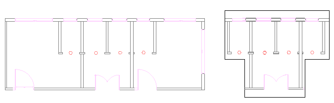
You can create one clipping boundary per Reference or Block. The clipping boundary can be a polyline, a rectangle, or a polygon.
The command creates a link between the Reference and the clipping boundary. Moving the clipping boundary moves the Reference also. Copying or rotating the clipped reference takes into account the boundary as well.
When you no longer need the clipping boundary, you can delete it. Deleting the clipping boundary does not delete the Reference.
Options of the command let you do the following:
- Dynamically change the boundary
- Invert the area to be hidden
- Hide or display the boundary
- Specify a clipping depth to when using the command with 3D entities
If you select a Reference and the ribbon is active, the Reference contextual tab appears. The contextual tab groups frequently used options and tools for working with References.
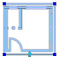
Resizing Clipping Boundaries
Additionally, you can change the shape or the size of the clipping boundary using grip points. A special grip point on the frame lets you invert the frame.
Note: Changing the boundary does not modify the entities in the Referenced drawing file.
Grip points available on the clipping boundary:
| Grip Point | Icon | Modifications |
|---|---|---|
| Standard |  |
Stretch, Resize |
| Invert |  |
Inverts the area to be hidden |
Example:
To clip References or Blocks:
- Specify the References or Blocks to which you want to apply a clipping boundary, and press Enter.
- Click Modify > Clip > Reference (or type ClipReference).
- Do one of the following:
- On the menu, click Modify > Clip > Reference.
- On the ribbon, click Insert > Reference > Manage References > Clip.
- Type ClipReference.
- Specify an option:
-
Boundary: Creates a new clipping boundary. If a clipping boundary already exists for the Reference or Block, you are prompted to delete the old boundary. Specify options:
- Invert clip: Lets you invert the display of the clipping boundary. Use the option to display the entities outside the boundary or to return to the previous mode.
- Polygonal: Lets you define an irregular polygonal shape as a clipping boundary by specifying points.
- Rectangular: Lets you define a rectangular clipping boundary around the area to keep by specifying two opposite points.
- Select polyline: Lets you select an existing PolyLine to serve as a clipping boundary. Arc segments are decurved.
-
Clip depth (used for 3D clipped References or Blocks): Sets the front and back planes parallel to the clipping boundary. You select the planes by specifying clip points. Use inferencing to select geometry. Specify options:
- Distance: Uses specified distances from the clipping boundary to create the front and back planes.
- Remove: Removes the clipping planes.
- Delete: Removes the clipping boundary.
- Off: Turns the clipping boundary off to display the Reference or Block entirely. The clipping boundary is retained so you can activate it again.
- On: Turns the clipping boundary on to display only the portion of the Reference or Block inside the clipping boundary.
- Polyline: Creates a PolyLine from the clipping boundary you created before (using the Rectangle and Polygonal options).
-
Boundary: Creates a new clipping boundary. If a clipping boundary already exists for the Reference or Block, you are prompted to delete the old boundary. Specify options:
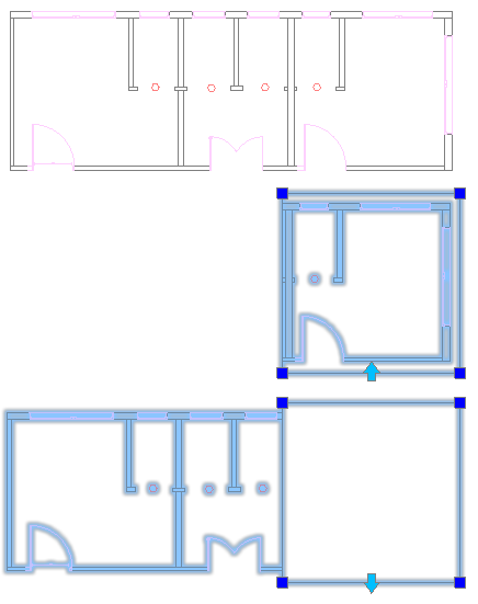
To invert a clipped Reference:
- Click the clipping boundary to invert to display the grip points.
- Click the grip point at the midpoint of the first edge of the boundary.
Example:
Access
Command: ClipReference
Menu: Modify > Clip > Reference
Ribbon: Insert > Reference > Clip > Reference
Contextual Ribbon: Reference > Clip
Opening Referenced Drawings
You can modify a drawing that is referenced in your drawing.
To open Referenced drawings:
- Specify a Referenced drawing.
- Click Tools > Open Reference (or type OpenReference).
- On the ribbon, click Reference > Manage References > Open.
-
The drawing opens in another drawing window. When you edit the drawing your modifications are reflected in the drawings where it is attached as a Reference.
Access
Command: OpenReference
Menu: Tools > Open Reference
Contextual Ribbon: Reference > Open Reference
Detaching Referenced Drawings
The DetachDrawing command lets you detach Referenced drawings that were attached to the current drawing with the AttachDrawing command.
To detach Referenced drawings:
- Type DetachDrawing at the command prompt.
- Type the name of the drawing to detach.
The names of the References attached to the drawing are listed in the References palette.
Access
Command: DetachDrawing
Working with Image Files
You can attach raster images (such as digital photographs or scanned maps) as References to the current drawing.
In practice, there are many situations when you have to add images in your drawings:
- Add a logo to a drawing title block
- Place a map behind the drawing
- Include aerial photographs
- Adding watermarks
The software provides tools and options to attach and detach images to your drawings and modify their scale and appearance. Additionally, you can clip images to a specified boundary and control image display properties.
Some of the supported file types are .bmp, .gif, .jpg, .jpeg, .png, .tif, and .tiff.
Images are not part of the drawing. The names of the images attached to the drawing are listed in the References palette.
The Properties palette lets you change several display properties of images that you attached to the drawing. You can:
- Adjust brightness to darken or lighten an image
- Adjust contrast to make an image easier to read
- Adjust fade and background transparency to see the drawing entities over images
If you select an image and the ribbon is active, the Image Selection contextual tab appears. The contextual tab groups options and tools for clipping and changing display properties.
This section discusses:
- Attaching Image Files as References
- Clipping Referenced Images
- Detaching Referenced Images
- Modifying Display Properties of Images
Attaching Image Files as References
You can attach an image to a drawing. Some of the supported file types are .bmp, .gif, .jpg, .jpeg, .png, .tif, and .tiff.
The names of the images attached to the drawing are listed in the References palette.
To attach image files as references:
Tip: Create a new layer for the image to attach. You can display or hide the image by turning the layer on or off.
- Click Insert > Reference Image (or type AttachImage).
- In the dialog box, select an image to attach, and click Open.
- In the Attach Reference: Image dialog box, Name displays the name of the file you selected, or you can select a previously attached image. Click Browse to select a different image.
- Specify File information:
-
Path type: Specifies how to display the path to the image.
- Full: Shows the complete path to the image.
- None: Shows only the file name.
- Relative: Shows the relative path to the image. If both drawing and image are in the same folder, only the file name of the image is displayed.
-
Path type: Specifies how to display the path to the image.
- Specify the Insertion point:
- Specify later: Lets you specify the insertion point in the graphics area after the dialog box closes.
- X, Y, Z: Specifies the X, Y, and Z coordinates for the image location.
- Specify the Scale:
- Specify later: Lets you specify the scale in the graphics area after the dialog box closes.
- Scale factor: Specifies the image scale.
- Specify the Rotation:
- Specify later: Lets you specify the angle in the graphics area after the dialog box closes.
- Angle: Sets the angle of rotation for the image.
- Click OK.
Access
Command: AttachImage
Menu: Insert > Reference Image
Ribbon: Insert > Reference > (Flyout) Attach
Tool Palettes: Draw > Attach Image
Clipping Referenced Images
You can display only part of a referenced image. The image is clipped at a boundary you create or specify.
You can create one clipping boundary per referenced image. The clipping boundary can be a polyline, a rectangle, or a polygon.
If you select an image and the ribbon is active, the Image Selection contextual tab appears. The contextual tab groups options and tools for creating and deleting clipping boundaries.
To clip referenced images using the contextual ribbon:
- Specify the referenced image to which you want to apply a clipping boundary.
When the ribbon is active, the Image Selection contextual ribbon tab appears.
- On the Reference panel, click Clip and specify an option from the flyout:
- Polygonal: Lets you define an irregular polygonal shape as clipping boundary by specifying points.
- Rectangular: Lets you define a rectangular clipping boundary by specifying two opposite points.
- Select polyline: Lets you select an existing PolyLine to serve as clipping boundary. Arc segments are decurved.
- Delete: Removes the clipping boundary.
To clip referenced images using the ClipImage command:
- Click Modify > Clip > Image (or type ClipImage).
- Specify the referenced image to which you want to apply a clipping boundary.
- Specify an option:
-
Create Boundary: Creates a new clipping boundary. If a clipping boundary already exists for the referenced image, you are prompted to delete the old boundary. Specify options:
- Polygonal: Lets you define an irregular polygonal shape as clipping boundary by specifying points.
- Rectangular: Lets you define a rectangular clipping boundary by specifying two opposite points.
- Select polyline: Lets you select an existing PolyLine to serve as clipping boundary. Arc segments are decurved.
- Delete: Removes the clipping boundary.
- Off: Turns the clipping boundary off to display the referenced image entirely. The clipping boundary is retained so you can activate it again.
- On: Turns the clipping boundary on to display only the portion of the referenced image inside the clipping boundary.
-
Create Boundary: Creates a new clipping boundary. If a clipping boundary already exists for the referenced image, you are prompted to delete the old boundary. Specify options:
Access
Command: ClipImage
Detaching Referenced Images
The DetachImage command lets you detach Referenced images that were attached to the current drawing with the AttachImage command.
To detach Referenced images:
- Type DetachImage at the command prompt.
- Type the name of the image you want to detach.
The names of the images attached to the drawing are listed in the References palette.
Access
Command: DetachImage
Using PDF Files as Underlays
You can attach one or more pages of PDF (Portable Document Format) documents to drawings as underlays.
When you attach a PDF file as an underlay, the software links the file as a reference to the current drawing.
If an attached PDF is organized in layers, you can control the visibility of the layers.
You can clip a PDF underlay to display only part of a PDF document.
The names of PDF underlays are listed in the References palette which lets you manage them.
If you select a PDF underlay in the graphics area and the ribbon is active, the PDF Underlay contextual tab appears. The contextual tab groups options and tools for clipping and changing PDF underlay display properties.
This chapter discusses:
- Attaching PDF Files as Underlays
- Controlling the Visibility of PDF Underlay Layers
- Clipping PDF Underlays
- Detaching PDF Underlays
- Setting PDF Underlay Options
- Managing PDF Underlays from the References Palette
Attaching PDF Files as Underlays
Use the AttachPDF command to attach pages of a PDF document to a drawing.
The command links the specified file as a reference to the current drawing.
To attach PDF files as Underlays:
- Click Insert > PDF Underlay (or type AttachPDF).
- Type AttachPDF at the command prompt.
- In the dialog box, select a PDF file to attach and click Open.
- In the dialog box, select a PDF file to attach and click Attach.
- In the Attach Reference: PDF Underlay dialog box, Name displays the name of the file you selected, or you can select a previously attached PDF file. Click Browse to select a different PDF file.
- In File information, specify the Path type:
- Full: Shows the complete path to the PDF file.
- None: Shows only the PDF file name.
- Relative: Shows the relative path to the PDF file. If the drawing and PDF file are in the same folder, only the file name of the image is displayed.
- If the PDF file contains multiple pages, select the pages of the PDF file to insert.
- Under Position, for X, Y, and Z, type coordinate values, or select Specify later to specify the insertion point on screen after closing the dialog box.
- Under Rotation, for Angle, type a value or select Specify later to set the rotation angle in the graphics area during insertion.
- Under Scale, type a scale factor, or select Specify later to specify the scaling on screen after closing the dialog box.
- Click OK.
Access
Command: AttachPDF
Menu: Insert > PDF Underlay
Ribbon: Insert > Reference > Attach > PDF
Tool Palettes: Draw > Attach PDF
Controlling the Visibility of PDF Underlay Layers
You can specify the visibility of layers of a PDF Underlay that is referenced PDF in a drawing.
To control the visibility of layers of an attached PDF file:
- In the graphics area, specify a PDF Underlay.
- Click Format > PDF Layer (or type LayersPDF).
- On the contextual ribbon, click Reference Manager > Layers.
-
In the dialog box, the PDF Underlay list displays the name of the PDF Underlay you specified. You can select a different, previously attached PDF file from this list.
- In the Layers list, activate the layers of the PDF file to display in the drawing.
If the specified PDF Underlay is not organized by layers, the list is empty.
- Click OK.
Access
Command: LayersPDF
Menu: Format > PDF Layer
Ribbon: Insert > Reference > Layers > PDF Underlay Layers Manager
Clipping PDF Underlays
You can display only part of a PDF Underlay. The entity is clipped at a boundary you create or specify.
You can create one clipping boundary per PDF Underlay.
To clip PDF Underlays:
- Specify the PDF Underlay to which you want to apply a clipping boundary.
- Click Modify > Clip > PDF Underlay (or type ClipPDF).
- On the contextual ribbon, click Reference Manager > Clip.
- Specify an option:
- On: Turns the clipping boundary on to display only the portion of the PDF Underlay inside the clipping boundary.
- Off: Turns the clipping boundary off to display the PDF Underlay entirely. The clipping boundary is retained so you can activate it again.
- Delete: Removes the clipping boundary.
-
Create Boundary: Creates a new clipping boundary. If a clipping boundary already exists for the PDF Underlay, you are prompted to delete the old boundary. Specify options:
- Select polyline: Uses an existing PolyLine as a clipping boundary. Arc segments are decurved.
- Polygonal: Lets you define an irregular polygonal shape as a clipping boundary by specifying points.
- Rectangular: Lets you define a rectangular clipping boundary by specifying two opposite points.
Access
Command: ClipPDF
Menu: Modify > Clip > PDF Underlay
Ribbon: Insert > Reference > Clip > PDF Underlay
Detaching PDF Underlays
The DetachPDF command lets you detach PDF Underlays that were attached to the current drawing with the AttachPDF command.
To detach PDF Underlays:
- Type DetachPDF at the command prompt.
- Type the name of the PDF Underlay to detach.
The names of the PDF Underlays attached to the drawing are listed in the References palette.
Access
Command: DetachPDF
Setting PDF Underlay Options
Use the PDFUnderlayOptions command to set EntitySnap access to PDF Underlay entities and control the frame visibility of PDF Underlays.
To control EntitySnap access to PDF Underlays:
- Type PDFUnderlayOptions at the command prompt.
- Specify the ESnap option.
- Specify On or Off to enable or disable EntitySnap access to PDF Underlays.
To control frame visibility of PDF Underlays:
- Type PDFUnderlayOptions at the command prompt.
- Specify the Frame option.
- Specify On or Off to show or hide the frame at the borders of PDF Underlays in the graphics area and on printouts.
If the ribbon is active, select a PDF underlay in the graphics area and control the frame visibility from the contextual ribbon tab: click PDF Underlay > Reference Manager > PDF Underlay frame Mode.
Access
Command: PDFUnderlayOptions
Managing PDF Underlays from the References Palette
The names of the PDF Underlays that you attach to a drawing are listed in the References palette. Use this palette to manage PDF Underlays.
To manage PDF Underlays from the References palette:
- Click Tools > References Manager.
- In the References palette, right-click an attached PDF file to access the following options:
- Open. Opens the PDF file from which you attached the underlay in an application which you use to show PDF files on your system.
- Attach. Opens the dialog box from which to attach selectively other pages from the previously attached PDF file. You can also browse to another PDF file to attach as underlay to the drawing.
- Unload. Unloads a loaded underlay.
-
Reload. Loads an underlay that has been unloaded. An unloaded underlay is indicated by
 .
. - Detach. Detaches the underlay.
-
Path.
Specifies how to relate the path to the underlay:
- Make absolute. Changes the relative path of the underlay to an absolute path.
- Make relative. Changes the absolute path of the underlay to a relative path.
- Remove path. Removes the path specification for the underlay. Use this option only, if the underlay is located in the same folder as the drawing.
Using DGN Files as Underlays
You can attach DGN drawing files (DesiGN files) as underlays. The files are linked as references to the current drawing.
Files of type *.dgn originate from MicroStation® or other CAD software.
In DGN files, a drawing can be separated into Design Models which are individual workspaces where design geometry is defined. When you attach a DGN file which contains multiple Design Models, the specified model is referenced.
You can specify layer visibility of a DGN Underlay that is a referenced DGN file in a drawing.
If you select a DGN underlay in the graphics area and the ribbon is active, the DGN Underlay contextual tab appears. The contextual tab groups options and tools for clipping and changing the appearance of the DGN underlay against the graphics area background.
- Attaching DGN Files as Underlays
- Controlling the Visibility of DGN Underlay Layers
- Clipping DGN Underlays
- Detaching DGN Underlays
- Setting DGN Underlay Options
- Adjusting DGN Underlays
- Managing DGN Underlays from the References Palette
Attaching DGN Files as Underlays
Use the AttachDGN command to attach a DGN drawing file (DesiGN file) as underlay to a drawing.
Files of type *.dgn originate from MicroStation® or other CAD software.
The command links the specified file as a reference to the current drawing.
If you select a DGN underlay in the graphics area and the ribbon is active, the DGN Underlay contextual tab appears. You can adjust and clip the DGN underlay.
To attach DGN files as underlays:
- Click Insert > DGN Underlay (or type AttachDGN).
- Type AttachDGN at the command prompt.
- In the dialog box, select a DGN file to attach and click Open.
- In the dialog box, select a DGN file to attach and click Attach.
- In the Attach Reference: DGN Underlay dialog box, Name displays the name of the file you selected, or you can select a previously attached DGN file. Click Browse to select a different DGN file.
- In File information, specify the Path type:
- Full. Shows the complete path to the DGN file.
- None. Shows only the DGN file name.
- Relative. Shows the relative path to the DGN file. If the drawing and DGN file are in the same folder, only the file name of the image appears.
- In Select a Design Model, select one of Design Models defined in the DGN drawing file.
In DGN files, a drawing can be separated into Design Models which are individual workspaces where design geometry is defined.
- In Conversion Units, specify whether unit conversion uses Master units or Sub units as its base.
Master units and Sub units express a relationship between applicable measurement units such as feet and inches, or meters and millimeters. Sub Units cannot be larger than Master Units.
The measurement units defined in the DGN file appear in the dialog box title in brackets.
If an instance of the specified DGN file is already referenced in the drawing, unit selection is unavailable.
- Under Insertion point, for X, Y, and Z, type coordinate values, or select Specify later to specify the insertion point on screen after closing the dialog box.
- Under Position, for X, Y, and Z, type coordinate values, or select Specify later to specify the insertion point on screen after closing the dialog box.
- Under Rotation, for Angle, type a value or select Specify later to specify the rotation angle in the graphics area during insertion.
- Under Scale, type a scale factor, or select Specify later to specify the scaling on screen after closing the dialog box.
- Click OK.
You can drag DGN underlays directly into your drawing. At the command prompt, you can specify the name of Design Model, an insertion point, the scale factor, and the rotation angle.
Access
Command: AttachDGN
Menu: Insert > DGN Underlay
Ribbon: Insert > Reference > Attach > DGN
Controlling the Visibility of DGN Underlay Layers
You can specify layer visibility of a DGN Underlay that is a referenced DGN file in a drawing.
To control the visibility of DGN Underlay layers:
- In the graphics area, specify a DGN Underlay.
- Click Format > DGN Layer (or type LayersDGN).
- On the contextual ribbon, click Reference Manager > Layers.
-
In the dialog box, DGN Underlay displays the name of the DGN Underlay you specified. You can select a different, previously attached DGN file from the list.
- In Layers, activate the layers of the DGN file to display in the drawing.
If the specified DGN Underlay is not organized by layers, the list is empty.
- Click OK.
Access
Command: LayersDGN
Menu: Format > DGN Layer
Ribbon: Insert > Reference > DGN Underlay Layer Manager
Clipping DGN Underlays
You can display only part of a DGN Underlay. The entity is clipped at a boundary you create or specify.
You can create one clipping boundary per DGN Underlay.
To clip DGN Underlays:
- Specify the DGN Underlay to which you want to apply a clipping boundary.
- Click Modify > Clip > DGN Underlay (or type ClipDGN).
- On the contextual ribbon, click Reference Manager > Clip.
- Specify an option:
- On: Turns the clipping boundary on to display only the portion of the DGN Underlay inside the clipping boundary.
- Off: Turns the clipping boundary off to display the DGN Underlay entirely. The clipping boundary is retained so you can activate it again.
- Delete: Removes the clipping boundary.
-
Create Boundary: Creates a new clipping boundary. If a clipping boundary already exists for the DGN Underlay, you are prompted to delete the old boundary. Specify an option:
- Select polyline: Uses an existing PolyLine as a clipping boundary. Arc segments are straightened.
- Polygonal: Lets you define a polygonal shape as a clipping boundary by specifying points.
- Rectangular: Lets you define a rectangular clipping boundary by specifying two opposite points.
Access
Command: ClipDGN
Menu: Modify > Clip > DGN Underlay
Ribbon: Insert > Reference > Clip > DGN Underlay
Detaching DGN Underlays
The DetachDGN command lets you detach DGN Underlays that were attached to the current drawing with the AttachDGN command.
To detach DGN Underlays:
- Type DetachDGN at the command prompt.
- Type the name of the DGN Underlay to detach.
The names of the DGN Underlays attached to the drawing are listed in the References palette.
Access
Command: DetachDGN
Setting DGN Underlay Options
Use the DGNUnderlayOptions command to set EntitySnap access to DGN Underlay entities and control the frame visibility of DGN Underlays.
To set EntitySnap access to DGN Underlays:
- Type DGNUnderlayOptions at the command prompt.
- Specify the ESnap option.
- Specify On or Off to enable or disable EntitySnap access to DGN Underlays.
To control frame visibility of DGN Underlays:
- Type DGNUnderlayOptions at the command prompt.
- Specify the Frame option.
- Specify an option:
- Show: Shows the frame at the borders of DGN Underlays in the graphics area and on printouts.
- Hide: Hides the frame in the graphics area and on printouts.
- Not printed: Shows the frame in the graphics area, but hides it on printouts.
If the ribbon is active, select a DGN underlay in the graphics area and control frame visibility from the contextual ribbon tab: click DGN Underlay > Reference Manager > DGN Underlay frame Mode.
Access
Command: DGNUnderlayOptions
Adjusting DGN Underlays
Use the AdjustDGN command to adjust the appearance of DGN Underlays against the graphics area background. You can adjust fade, contrast, and monochrome values. The settings do not affect the original file. When you print the drawing the settings are recognized.
To adjust DGN Underlays:
- Type AdjustDGN at the command prompt.
- In the graphics area, specify a DGN underlay and press Enter.
- Specify options:
- Fade. Sets the fade value. Values range between 0 (no transparency) and 100 (full transparency).
- Contrast. Sets the contrast value. Values range between 0 (no contrast) and 100 (full contrast).
- Monochrome. Specifies whether the underlay displays monochrome or with its original colors.
Note: The options for changing the appearance of the DGN underlay against the graphics area background are available on the DGN Underlay contextual ribbon tab.
If the ribbon is active, select a DGN underlay in the graphics area and control the appearance of the DGN underlay against the graphics area background from the DGN Underlay contextual ribbon tab.
Access
Command: AdjustDGN
Managing DGN Underlays from the References Palette
The names of the DGN Underlays that you attach to a drawing are listed in the References palette. Use this palette to manage DGN Underlays.
To manage DGN Underlays from the References palette:
- Click Tools > References Manager.
- In the References palette, right-click an attached DGN file to access the following options:
- Attach. Opens the dialog box from which to attach selectively other design models from the previously attached DGN file. You can also browse to another DGN file to attach as underlay to the drawing.
- Unload. Unloads a loaded underlay.
-
Reload. Loads an underlay that has been unloaded. An unloaded underlay is indicated by .
- Detach. Detaches the underlay.
In-Place Editing of Blocks and References
In-place editing lets you modify the definitions of Components, which are Block definitions or referenced drawings in the current drawing (referred to as Elements).
Component instances in the drawing reflect the changes immediately.
This section describes how to:
- Edit Components in-place
- Add or remove Elements during Component editing
- Modify the base point of a Block definition
- Save Component edits
- Terminate Component editing
In-Place Editing of Components
Use the EditComponent command to edit individual Elements within referenced Blocks or drawings directly in the current drawing, changing the definition of Blocks or References.
All instances of modified Blocks and References are updated in the drawing.
Block insertions and attached References behave as single Elements in drawings. They are referred to as Components. You can move, copy, mirror, rotate or scale Components, but the Elements that make up a Component are not accessible by default. The EditComponent command starts a Component editing session, also referred to as in-place editing. During a Component editing session, you can access and modify individual Elements of Blocks and References. You can add to Components or remove Elements from them.
Additionally, you can automatically include all nested Blocks in the Component editing session or specify the nested Block to edit in-place.
To finish the Component editing session, use the SaveComponent or CloseComponent commands.
To modify a Block definition:
- Click Modify > Component > Edit (or type EditComponent at the command prompt).
- In the graphics area click a Block or Reference to edit.
- From the list in the Edit Component dialog box, select the name of a Block or Reference:
- If you select a Block or Reference that does not contain further Blocks or References, the list contains only that Block or Reference.
- If you select a Block that contains other Blocks, or a Reference that contains Blocks or other References, the nesting is displayed in a hierarchical list. Additionally, you can control how nested Blocks are selected:
- Automatically select all nested entities. Lets you specify any entity contained within the specified nested Block in the tree. The Component editing session starts immediately.
- Prompt to select nested entities. Lets you individually specify the nested Block in the graphics area before starting the Component editing session.
- For nested blocks, you can control nested entities selection during an editing session.
- If you want to zoom to the imaginary bounding box that surrounds the selected Block or Reference, click Zoom to Bounds before you click Show Selection or OK.
- Click Show Selection to highlight the Block or Reference in the drawing before you start editing.
The dialog box temporarily disappears until you click in the graphics area or press Esc to return to the dialog box.
- Click OK to start in-place editing of the Block or Reference you selected.
The drawing is dimmed except for the Elements that define the Block or Reference.
- Modify the geometry of the Block definition or Reference using modification tools and commands.
Use the ChangeElements command to add or remove entities in the Block definition or Reference.
- Type SaveComponent to accept the changes to the Component
– or –
Type CloseComponent to open the Component dialog box so you can Save or Discard the modifications.
To modify the hierarchy of nested Blocks:
- Click Modify > Component > Edit (or type EditComponent).
- In the graphics area click a Block containing other Blocks.
- From the list in the Edit Component dialog box select a nested Block.
- Click Move Up to move the nested Block a level higher and repeat as needed.
Click Restore to bring a moved Block back into its original position.
- Click OK.
- Type SaveComponent to accept the changes to the Component
– or –
Type CloseComponent to open the Component dialog box so you can Save or Discard the modifications.
You cannot modify the hierarchy of nested Blocks in References.
Access
Command: EditComponent
Menu: Modify > Component > Edit
Ribbon: Insert > Component > Edit Component
Adding or Removing Elements During Component Editing
The ChangeElements command adds or removes Elements from Component definitions (Blocks or References).
Entities contained in Components are referred to as Elements. Elements can be Lines, Arcs, Circles, or other Components, for example.
To add Elements to Components during in-place editing:
- Click Modify > Component > Edit (or type EditComponent at the command prompt) to start in-place editing of Components.
- In the graphics area click a Block or Reference to edit.
- In the Edit Component dialog box, select the Block or Reference to modify and click OK.
- All Elements are dimmed except for those you can edit in place.
- Draw or insert the Elements to add to the selected Block definition or Reference.
- Click Modify > Component > Add Elements (or type ChangeElements and enter the Add option).
- Select the Elements you want to add to the Block definition or Reference.
- Click Modify > Component > Save and Close (or typeSaveComponent).
- All instances of the Block or the Reference are updated and display the added Elements.
To remove Elements from Components during in-place editing:
- Click Modify > Component > Edit (or type EditComponent at the command prompt) to start in-place editing of Components.
- In the graphics area click a Block or Reference to edit.
- In the Edit Component dialog box, select the Block or Reference to modify and click OK.
- All Elements are dimmed except those you can edit in place.
- Click Modify > Component > Remove Elements (or type ChangeElements and enter the Remove option).
- Select the Elements you want to remove from the Block definition or Reference.
- Click Modify > Component > Save and Close (or typeSaveComponent).
- All instances of the Block or Reference are updated.
Access
Command: ChangeElements
Menu: Modify > Component > Add Elements and Modify > Component > Remove Elements
Modifying the Base Point of a Block Definition
Use the EditBasePoint command to set a new insertion base point for a Block definition.
You must first use the EditComponent command to enter Component editing mode to use this command.
To modify the base point of a Block definition or Reference:
- Click Modify > Component > Edit (or type EditComponent at the command prompt) to start in-place editing of Blocks.
- In the Edit Component dialog box, select the Block to modify and click OK.
- Note: You cannot modify the base point of a Block nested in a referenced drawing.
- Click Modify > Component > Edit Base Point (or type EditBasePoint at the command prompt).
- A rubberband displays between the current base point of the Block and the pointer.
- Specify the new base point.
- Click Modify > Component > Save and Close (or typeSaveComponent) to accept the change and complete the in-place editing of the Block definition.
Use CloseComponent instead of SaveComponent to specify whether you want to save or discard the changes of a Component editing session.
Access
Command: EditBasePoint
Menu: Modify > Component > Edit Base Point
Ribbon: Insert > Component > Edit Base Point
Saving Component Edits
The SaveComponent command saves changes made during a Component editing session and ends the session. In-place editing of Block definitions or References is invoked by the EditComponent command.
To save an in-place edited Block definition or Reference:
- Click Modify > Component > Save and Close (or type SaveComponent at the command prompt).
The Block definition or Reference changes are saved and Component editing mode ends.
All instances of the Block or Reference in the drawing reflect the changes.
Use CloseComponent to save or discard the modifications of in-place editing of Components.
Access
Command: SaveComponent
Menu: Modify > Component > Save and Close
Ribbon: Insert > Component > Save and Close
Terminating Component Editing
The CloseComponent command ends the in-place editing of a Block definition or Reference initiated by the EditComponent command.
To end in-place editing of a Block definition or Reference:
- Click Modify > Component > Close (or type CloseComponent at the command prompt).
- In the Component dialog box, click Save to save the changes of the Block definition or Reference you have edited
– or –
Click Discard to end Component editing without saving the changes.
Use SaveComponent to save the changes and end the Component editing session.
Access
Command: CloseComponent
Menu: Modify > Component > Close
Ribbon: Insert > Component > Close Component
Working with Nested Blocks
You can use Blocks within Block definitions to simplify the structure of a complex Block. A Block definition that contains one or more Block definitions is called a nested Block.
The following topics help you work with nested Blocks:
About Nested Blocks
You can use Blocks within Block definitions to simplify the structure of a complex Block. A Block embedded in another Block is called a nested Block.
Example:
The Block Workplace contains two Blocks: Chair and Desk.
Chair and Desk are nested into Workplace.
The Block Tableset contains one Block for the table and several Blocks for chairs.
Table and Chair Blocks are nested into Tableset.
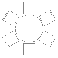
In practice, there are situation when nested Blocks are accidentally created. For example, when inserting a drawing as Block, then Blocks from the drawing are nested.
All Blocks from the drawing, including the nested Blocks are accessible from the Block Structure palette.
Note: A nested Block definition may contain other nested Blocks. Nested Blocks cannot reference themselves.
The Block Structure Palette
All Blocks from a drawing, including nested Blocks are accessible from the Block Structure palette. At any time, you can insert Blocks into your drawing.
The Block Structure palette lets you find and insert Blocks.
From the Block Structure palette, you can:
- Display the structure of the Blocks from the current drawing
- Insert Blocks into the active drawing
- Delete Blocks from the current drawing
- Rename Blocks from the current drawing
- Hide and display Blocks from the current drawing
Use the BlockStructure command to display the Block Structure palette.
Toolbar
Use the buttons on the toolbar at the top of the Block Structure palette to access and use Blocks from the current drawing.
-
Information Toggle
 . Turns on and off the Information area of the palette.
 -
Preview Toggle
 . Toggles the preview of the selected Block.
 -
Refresh
 . Refreshes the list of available Blocks. For example, if new Blocks were added in the current drawing, they will be displayed in the tree.
Block Structure
Displays the Blocks from the current drawing in a tree view, alphabetically ordered. Thumbnails update when you modify and save the Block. Optionally, you can display captions for thumbnails.
Selecting a Block from the Block Structure, highlights the Block in the graphics area.
Right-clicking an item displays a menu with the following options:
- Insert. Inserts the specified Block as if you used the -InsertBlock command.
- Rename. Opens the Rename Block dialog box where you can specify the new name of the Block.
- Delete. Deletes the specified Block from the block library.
To insert a Block from the Block Structure palette:
Note: You can drag a Block or one of the contained Blocks and drop it on the graphics area.
- Do one of the following:
- Drag a Block and drop it into the active drawing.
- Right-click on a block name and select Insert from the context menu.
To rename a Block from the Block Structure palette:
- On the Block Structure palette, right-click a block name and select Rename from the context menu.
- In the Rename Block dialog box, specify the new name and click Rename.
Information
Displays information about the selected Block.
- Rotation.
- Block Units.
- Block Unit Scale.
- Annotative.
Preview
Displays a preview of the Block that you selected in the Block Structure.
Access
Command: BlockStructure
Menu: Tools > Block Structure
Ribbon: Insert > Palettes > Block Structure
Customizing Block Behavior and Appearance
You can define rules and constraints for Block definitions to control the Block reference behavior and appearance in a drawings. Blocks that have these rules and constraints are named CustomBlocks.
CustomBlocks let you use a single Block that changes its shape, size, or appearance instead of a set of similar Block definitions.
This section discusses:
- CustomBlocks Basics
- Creating CustomBlocks
- Editing Block Definitions
- Modifying CustomBlock References
CustomBlocks Basics
CustomBlocks are Blocks for which you define rules and constraints that let you quickly change their size, rotation, and appearance when you insert them into drawings.
Use CustomBlocks when you have several similar Blocks in your project. CustomBlocks reduces your drafting time and the number of Blocks to manage.
For example, you can define a single CustomBlock to represent a rectangular table with chairs in a drawing. You can use the CustomBlock to represent other tables with various lengths while maintaining the size and relative positions of the chairs. You can modify the CustomBlock to represent tables with a different number of chairs or tables with other shapes.
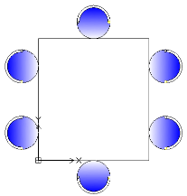
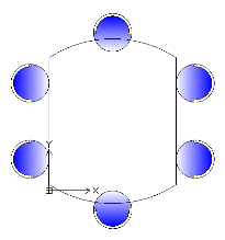
In addition to the geometric entities, CustomBlock definitions contain special features, such as elements, activities, and constraints:
- Elements define grip points and custom properties for the CustomBlock.
- Activities specify how the CustomBlock reference moves or changes when you manipulate grip points and modify custom properties.
- Constraints define relationships between entities of the CustomBlock.
You can create a CustomBlock from any existing Block by adding the features to the Block definition in the Block Editor.
CustomBlock features let you:
- Create additional grip points on a subset of entities in a Block to allow move, stretch, rotate, scale, pattern, and mirror (elements and activities)
Elements such as point, linear, polar, XY, rotation, and mirror define grip points on geometric entities in a Block. You can apply activities to each element. In the Block reference, activities behave similar to the commands. See Adding Elements.
- Define predefined sets and values for custom properties
You can use value tables to associate a list of custom property values to a CustomBlock. See Associating Data to CustomBlocks.
- Define specific constraints to maintain relationships between Block entities. See Working with Constraints.
- Restrict entity dimensions to specific values and increments (value sets)
- Define sets of entities to display in a Block reference
You can use visibility states to specify which entities of the CustomBlock appear in the Block reference. See Controlling the Visibility of CustomBlock Entities.
After inserting a CustomBlock into a drawing, you can select it and modify the CustomBlock appearance using the grip points and custom properties that you added in the CustomBlock definition. For example:
- Modify Block references within specific constraints
- Select between variants in a Block
- Change the appearance by turning certain entities on or off
- Cycle through a set of base points when inserting CustomBlocks
- Specify forms and sizes from predefined sets and values
Note: Use the ResetBlock command to reset Block references to default values of the CustomBlock definitions.
Differences Between Simple Blocks and CustomBlocks
- The reference of a simple Block always has only one grip point at the Block base point. A CustomBlock reference has additional grip points, which you specify in the CustomBlock definition.
- All Block references of a simple Block look exactly the same. Moreover, changing a Block reference changes the Block definition and all Block references. CustomBlock references may have different appearances and you can modify them separately from the CustomBlock definition. Changing a CustomBlock reference does not update all references.
The Block Editor
The Block Editor is an environment where you can draw and modify geometric entities of Blocks. Additionally, the Block Editor provides tools for adding constraints, elements, and activities to a CustomBlock definition.
To open the Block Editor, use the EditBlock command. See Using the Block Editor.
Note: When opening the Block Editor, only the CustomBlock geometry appears. The origin of the coordinate system is at the Block insertion point.
Adding Elements and Activities
You can use the Block Editor at any time to add elements and activities to a Block definition, which lets you control the Block appearance later, after inserting the Block in the drawing.
Activities specify how to change the Block, while Elements specify the CustomBlock entities that the associated activity affects.
Open the Block definition in the Block Editor, place the suitable element on each entity you want to modify in the Block reference, and apply the required activities. The element defines grip points and custom properties that are visible outside the Block Editor.
In the Block reference, each element appears as a special grip point associated with an activity. Custom properties defined by the element appear in the Properties palette, under Custom. Moving a grip point or modifying a property triggers the associated activity, which changes the appearance of the CustomBlock reference.
Example:
For example, place a linear element (with one grip point) along a wall to specify that you want to change it during the insertion. To change the length of the wall, assign a Stretch activity to the Linear element. In the Block reference, the grip point lets you extend the wall.
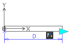
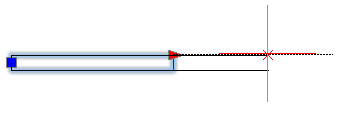
Note: You can use elements and activities only in certain combinations. See About Custom Block Elements.
Adding Constraints
Use Constraints in the CustomBlock definitions to specify relationships between entities. The Block Editor provides geometric constraints that you can add to the CustomBlock definition. See Geometric Constraints.
Additionally, you can use Dimensional Constraints tools to maintain specified distance, length, diameter, radius, and angle values between entities of the CustomBlock definition.
Note: Dimensional Constraints are not available in the Block Editor interface.
To add a dimensional Constraint to a Block definition:
- Type EditBlock at the command prompt.
- In the graphics area, specify the Block.
- In the Edit Block dialog box, click OK.
- In the Block Editor, type DimensionalConstraint at the command prompt.
- Follow the command prompts.
- Type CBSave at the command prompt to save the CustomBlock.
Creating CustomBlocks
You can create CustomBlocks by adding constraints, activities, and elements to existing Blocks in the Block Editor.
To create a CustomBlock:
- Plan the CustomBlock in advance.
Before creating a CustomBlock, carefully consider what you want to create. Take into account the sizes that should change, the relationship between entities, and the set of entities that vary or not.
- Define the Block.
Draw the entities in the graphics area and define the Block using the MakeBlock command.
- Open the Block in the Block Editor.
You can create a CustomBlock from any existing Block by adding the required features to its definition in the Block Editor. This lets you control the CustomBlock appearance after you insert the CustomBlock in the drawing. See Using the Block Editor.
Note: Use the EditBlock command to open a specified Block in the Block Editor.
- Apply constraints to the CustomBlock.
Specify the geometric and dimensional constraints using the available tools. Applying constraints forces geometric assemblies to modify their shapes and positions. See Adding Constraints.
- Add elements to the CustomBlock.
Add elements to specify entities that you want to change. Specify the number of grip points and their positions. See Adding Elements.
- Apply activities to the elements.
Associate activities to elements to specify how to change. See Applying Activities to CustomBlock Definitions.
- Test the CustomBlock.
Test the CustomBlock definition without closing the Block Editor. See Testing CustomBlocks.
- Save the CustomBlock.
Save the CustomBlock definition under a specified name for later use within a drawing. See Saving CustomBlocks.
This topic discusses:
- Using the Block Editor
- Adding Elements
- Applying Activities to CustomBlock Definitions
- Using Element Sets
- Controlling the Visibility of CustomBlock Entities
- Associating Data to CustomBlocks
- Testing CustomBlocks
Using the Block Editor
The Block Editor provides all the tools you need to create and modify CustomBlocks.
This section discusses:
- The Block Editor
- Editing Block Definitions
- Inserting CustomBlocks
- Specifying CustomBlock Properties
- Saving CustomBlocks
The Block Editor
The Block Editor is an environment where you can draw and modify Blocks. Additionally, the Block Editor provides tools for adding constraints, elements, and activities to the CustomBlock definition.
The Block Editor provides:
- Graphics area with a gray background
- Contextual toolbars that contain various operations
- The Properties palette.
You can select and modify the properties of entities in the graphics area such as geometric entities, elements, and activities.
- Test window to test the CustomBlock before saving it
Block Editor commands:
| Command | Description |
|---|---|
| CBActivity | Creates and applies an activity to a CustomBlock element. |
| CBActivityIcon | Controls the visibility of activity icons. |
| CBActivityTool | Creates and applies activities to existing CustomBlock elements. |
| CBClose | Closes the Block Editor. |
| CBCycleOrder | Specifies the cycling order for grip points that you can use as insertion points of CustomBlock references. |
| CBElement | Creates a CustomBlock element. |
| CBElementSet | Creates an element and an associated activity. |
| CBHide | Sets hidden entities for the visibility state. |
| CBOptions | Displays the Block Editor options. |
| CBSave | Saves the CustomBlock definition under the current name. |
| CBSaveAs | Saves the CustomBlock definition with a specified name. |
| CBShow | Sets visible entities for the visibility state. |
| CBTestBlock | Opens a test window for the current Block definition. |
| CBTestClose | Closes the test window. |
| CBValueTable | Displays the Property Value Table dialog box. |
| CBVisibility | Displays the Visibility States dialog box (dialog box variant). |
| -CBVisibility | Creates, sets, or deletes visibility states of a CustomBlock definition (command window variant). |
| CBWBlockAs | Saves a CustomBlock as a separate drawing. |
CCS in the Block Editor
The origin of the CCS defines the Block base point. You can use the base point to move the Block reference.
If you move the Block geometry relative to the origin of the CCS in the Block Editor, the base point changes in the Block references. Alternatively, you can add a base point element to the Block definition. The base point position in the Block Editor defines the base point position in the Block reference, allowing you to move the Block within the drawing.
Note: The CCS command is not available in the Block Editor.
Starting the Block Editor
To open the Block Editor, use the EditBlock command.
Alternatively, double-click a Block reference in the graphics area.
During an editing session, you can do the following changes to a specified Block:
- Modify the geometry using modification tools and commands. You can add, delete, and modify the Block entities.
- Modify the properties of any entity from the graphics area using the Properties palette.
- Add elements and activities to the Block definitions to create CustomBlocks.
To start the Block Editor:
- Do one of the following:
- On the ribbon, click Insert > Block > Edit Block.
- On the menu, click Modify > Entity Edit Block.
- Type EditBlock.
- In the graphics area, click a Block reference.
- From the list in the Edit Block dialog box, select the name of a Block.
Note: You can select simple Blocks or CustomBlocks. An orange dot in the right-bottom corner of the icon identifies CustomBlocks. Additionally, the preview image displays the CB abbreviation for the selected CustomBlock.
- Click OK.
The Block geometry appears in the Block Editor. The origin of the coordinate system is in the Block insertion point.
Note: To finish the Block editing session, use the CBClose command.
Editing Block Definitions
Use the Block Editor to edit Block definitions. To open the Block Editor, use the EditBlock command. Alternatively, double-click a Block reference in the graphics area.
You can do the following changes to the Block:
- Modify geometry using modification tools and commands. You can add, delete, and modify the Block entities.
- Modify properties of any entity in the graphics area by using the Properties palette.
- Add elements and activities to the Block definitions to create CustomBlocks.
You can add, delete, and modify these entities within a CustomBlock definition:
- Constraints
- Elements
- Activities
- Visibility states
- Value tables
- Grip points
- Custom properties
The Properties palette is available in the Block Editor. You can select and modify the properties of entities in the graphics area such as geometric entities, elements, and activities.
The Properties palette is available in the Block Editor. You can select and modify the properties of geometric entities in the graphics area.
To finish the Block editing session, use the CBClose command and save the Block. See Saving CustomBlocks.
All instances of modified Blocks and References update in the drawing.
To open a Block definition for editing:
- Click Modify > Entity > Edit Block (or type EditBlock).
- In the graphics area, click the Block to edit.
- From the list in the Edit Block dialog box, select the name of the Block.
Note: You can edit simple Blocks only. An orange dot in the bottom-right corner of the icon identifies CustomBlocks. In addition, the preview image displays the CB abbreviation for the selected CustomBlock.
- To zoom to the bounding box that surrounds the selected Block, select Zoom to Bounds.
- Click Show Selection to highlight the Block in the drawing before you start editing.
The dialog box temporarily disappears until you click in the graphics area or press Esc to return to the dialog box.
- Click OK.
The Block Editor opens. The Block geometry appears. The origin of the coordinate system is in the Block insertion point.
- Do the required changes to the Block definition. You can add, delete, and modify the following:
- Geometric Constraints
- Elements
- Activities
- Block entities
- Visibility states
- Tables
- Base point
- Grips
- Properties
- Modify the geometry using modification tools and commands.
- Type CBSave to accept the changes.
-
Type CBClose to exit the editor.
To close the Block Editor:
- Type CBClose at the command prompt.
If the Block definition has changed since you last saved it, the system prompts you to save the changes.
- Save or discard the changes.
Access
Command: EditBlock
Menu: Modify > Entity > Edit Block
Ribbon: Insert > Block > Edit Block
Saving CustomBlocks
You can save a CustomBlock definition for later use within a drawing.
To save the CustomBlock, use CBSave and CBSaveAs commands. In addition, you can use the CBWBlockAs to save the CustomBlock as a separate drawing.
This section discusses:
Saving a CustomBlock
Use the CBSave command to save the CustomBlock with the current name.
Note: When saving CustomBlocks, the current values of the elements become the default values of the reference.
To save a CustomBlock:
- Do one of the following:
- On the ribbon, click Edit Block > Save > Save.
- Type CBSave.
Access
Command: CBSave
Ribbon: > Edit Block > Save > Save
Renaming a CustomBlock
Use the CBSaveAs command to save a CustomBlock with a different name.
To rename a CustomBlock:
- Type CBSaveAs at the command prompt.
- In the dialog box, specify the new name.
- Click OK.
- Click Yes to replace the Block definition or No to create a new CustomBlock.
Access
Command: CBSaveAs
Ribbon: Edit Block > Save > CBSaveAs
Saving a CustomBlock as a Separate Drawing
You can save a CustomBlock as a separate drawing file that you can insert into other drawings.
Use the CBWBlockAs command to save a Block as a separate drawing with a specified name.
To save a CustomBlock as a separate drawing:
- Open the Block in the Block Editor.
- Type CBWBlockAs at the command prompt.
- In the dialog box, specify the new name of the Block. This name becomes the name of the drawing file.
- Select Save Block as separate drawing.
- Click OK.
- Navigate to the folder where you want to store the drawing file and click Save.
Access
Command: CBWBlockAs
Adding Constraints to CustomBlock Definitions
Within a CustomBlock, you can apply constraints to maintain geometric relationships and size as you modify the CustomBlock.
This chapter discusses:
- About Constraints within CustomBlocks
- Applying Constraint Parameters to CustomBlock Entities
- Managing Parameters of a CustomBlock Definition
Adding Constraints to CustomBlocks
Within a CustomBlock, you can apply constraints to maintain geometric relationships and size as you modify the CustomBlock.
- Geometric constraints define the relationship between entities of the CustomBlock definition. For example, you can specify that two circles should always remain concentric or that a side of a polygon should always be horizontal.
- Dimensional constraints let you control the size of entities of the CustomBlock. For example, you can define dimensional constraints to maintain the length of a polygon segment.
Constraint parameters let you specify how entities relate to each other, so that the geometry is preserved while changing the entity size.
Dimensional Constraints Parameters
Dimensional constraints from the Block Editor are called constraint parameters.
Constraint parameters let you expose custom grip points and custom properties of the CustomBlock. Using constraint parameters you can control the distance, length, diameter, radius, and angle values of entities within a CustomBlock. Changing the value of constraint parameters changes the size of the related entities.
Additionally, you can define mathematical expressions to specify relationships between constraint parameters. For example, you can specify that the diameter of a circle is always half of the length of another entity.
You can use both, dimensional constraints and constraint parameters in CustomBlock definitions. Also, you can convert existing dimensional constraints into constraints parameters.
In the Block Editor, the tools for adding constraint parameters are grouped on the Dimensional panel of the Edit Block ribbon tab.
Use the CBCElement command to add a dimensional constraint parameter to an entity of a CustomBlock definition. Command options correspond to the choices provided by individual element commands from the Block Editor (Dimensional panel).
Example:
d1 is a dimensional constraint parameter
d2 is a dimensional constraint

User Parameters in CustomBlocks
User parameters let you define editable custom properties for a Block reference. Blocks update automatically if any user parameter is changed.
In the Block Editor, the Parameters palette lists:
- Action parameters
- Dimensional constraint parameters
- User parameters
- Attributes
To convert a dimensional constraints into a dimensional constraint parameter:
- In the Block Editor, select a dimensional constraint.
- On the ribbon, click Edit Block > Dimensional > Convert.
In the Parameters palette, the specified dimensional constraint is moved under Dimensional Parameters.
Parent Topic
Applying Constraint Parameters to CustomBlock Entities
Use the CBCElement command to apply dimensional constraint parameters to specified entities of a CustomBlock or to convert dimensional constraints to dimensional constraint parameters.
Using constraint parameters you can control the distance, length, diameter, radius, and angle values of entities within a CustomBlock. Changing the value of constraint parameters changes the size of the related entities.
To apply a constraint parameter:
- In the Block Editor, type CBCElement at the command prompt.
Command options correspond to the choices provided by individual element commands from the Block Editor (Dimensional panel).
- Specify an option:
- Linear. Creates a linear horizontal or vertical constraint parameter based on two specified points in the CustomBlock definition.
- Horizontal. Constrains the X distance of a line or between two points on different entities.
- Vertical. Constrains the Y distance of a line or between two points on different entities.
- Aligned. Constrains the direct distance between two points on different entities, two lines, or a point on an entity and a line.
- Angular. Constrains the angle between two Lines or PolyLine segments, the total angle of an Arc or curved PolyLine segment.
- Radius. Constrains the radius of a Circle, Arc, or curved PolyLine segment.
- Diameter. Constrains the diameter of a Circle, Arc, or curved PolyLine segment.
-
Convert. Converts the dimensional constraints to constraint parameters.
Entities other than dimensional constraints are ignored and filtered from the selection set.
- Follow the command prompts.
The subsequent sequences of the CBCElement command are identical to those of the individual command variants.
Access
Command: CBCElement
Managing Parameters of a CustomBlock Definition
In the Block Editor, the Parameters palette lists all parameters, constraints, and attributes from the block definition.
- Action parameters
- Dimensional constraints
- Dimensional parameters
- User parameters
- Attributes
You can do the following changes to parameters:
- Rename parameters
- Parameter names are automatically updated in all Blocks from the Block Editor.
- Define new equations or modify existing ones
To display the Parameters Manager palette:
- Do one of the following:
- On the menu, click Constraints > Parameters Manager.
- On the ribbon, click Constraints > Manage > Parameters Manager.
- Type Parameters.
To create a dimensional constraint parameter:
- In the Block Editor, apply a dimensional constraint parameter to an entity of a Block definition.
In the Parameters palette, the dimensional constraint parameter appears under the Dimensional Constraint Parameters category.
To delete a dimensional parameter:
- On the Parameters list, under Dimensional Parameters, click a dimensional parameter.
- Click Delete user parameter
 . Alternatively, you can right-click the dimensional parameter and select Delete Parameter from the context menu.
 - The corresponding dimensional constraint is removed from the graphics area.
- If the parameter is referenced by a Dimensional Constraint in the drawing or in an expression, you are prompted to confirm deletion.
To create a user-defined parameter for a CustomBlock definition:
- On the Parameters palette, click Create a new user parameter
 .
. - Under User-defined, a new entry appears.
- If necessary, in Name, edit the variable name.
Note: Name cannot begin with a number, contain spaces, or exceed 256 characters.
- In Expression, type a value or an expression.
- The value that results from the expression displays In Value.
Use the Parameters command to display the Parameters Manager palette to view Dimensional Constraints parameter.
The Parameter Palette (Block Editor)
Toolbar
| Button | See also |
|---|---|
|
Creates a new user-defined parameter. Note: You can only add user-defined parameters to the list |
|
Deletes the selected parameter from the list |
Filters
Lets you filter the display of user-defined variables in the list:
- All parameters: Displays all user-defined variables.
- Used parameters: Displays only the user-defined variables used in expressions.
- Unused parameters: Displays only the user-defined variables not used in expressions. Right-click, then click Delete Parameter to remove unused variables from the list.
Search for a Parameter
Lets you search parameters by their name. Type the name of the parameter in the search box and press Enter.
Parameters List
In the list, parameters are grouped in the following categories:
- Action parameters
- Dimensional constraint parameters
- Dimensional constraints
- User parameters
- Attributes
The list header columns represents the properties of the parameters.
By default, the Parameters palette lists:
- Name. Displays names of the dimensional constraints
- Expression. Display an equation or a value
- Value. Values that result from the expression
- Order. Lets you change the order of the properties displayed in the Properties palette
- Show. Displays the parameter as property of the block reference
Additional columns include:
- Type. Displays the type of the dimensional constraint or variable value
- Description. Displays the notes associated with of the user variable
To show or hide columns, right-click the list header and use the context menu to display the desired columns in the list.
Clicking a column head sorts the parameters in an ascending or descending order.
At any moment, you can resize columns or move them to another position.
Use the Maximize All Columns option to display all columns using the maximum value in each column as the base.
Access
Command: Parameters
Menu: Constraints > Parameters Manager
Ribbon: Constraints > Manage > Parameters Manager
Adding Elements
Use elements to specify the entities of the CustomBlock that the associated activity affects.
This section discusses:
About CustomBlock Elements
Elements specify the entities of the CustomBlock that the associated activity affects.
You can add elements to a CustomBlock definition using the tools in the Block Editor.
Note: A CustomBlock definition must contain at least one element.
In CustomBlock definitions, elements specify points, distances, and angles that you want to modify in the Block reference.
When defining a CustomBlock element, you can specify:
- Special grip points to display on the Block geometry. Use the grip points to manipulate the Block reference outside the Block Editor. By default, grip points apear at the main points of the element.
- Labels to identify the properties defined by the element. The labels appear under Custom in the Properties palette where you can modify values or select options. Double-clicking an element label switches the label to editing mode.
You can use elements and activities in certain combinations only. These elements are available in the Block Editor and you can associate activities with them as follows:
| Element | Description | Available activities |
|---|---|---|
| Point | Defines the X and Y properties of the Block reference. | Move, Stretch |
| Linear | Defines the distance between two points in the CustomBlock definition. | Move, Stretch, Scale, Pattern |
| Polar | Defines the distance between two points and displays an angle value. | Move, Stretch, Scale, Pattern, Polar |
| XY | Defines the X and Y distance from the base point of the element. | Move, Stretch, Scale, Pattern |
| Rotation | Defines an angle for the CustomBlock reference. | Rotate |
| Alignment | Defines an alignment axis for the CustomBlock reference. | – |
| Mirror | Defines a mirror axis for the CustomBlock reference. | Mirror |
| Visibility | Defines visibility states. You can add only one visibility element to a CustomBlock definition. | – |
| Table | Defines a custom property that you can associate with a list of defined values for other elements. | Table activity |
| Basepoint | Defines one base point for the CustomBlock reference relative to the CustomBlock geometry | – |
Use elements to specify the properties and grip points of the entity that you want to customize are visible and accessible outside the Block Editor.
Example:
Place a linear element on a wall to specify that you want to change the wall length during the insertion. To change the length of a linear entity, assign a Stretch activity to the Linear element.
Elements Representation
In the Block Editor, elements look very similar to Dimensions. The software automatically adds grip points that are associated with the main points of the elements.
Note: Only elements that have associated activities display grip points in the Block reference.
In the Block Editor, elements that do not have associated activities display this icon ![]() .
.
Double-clicking the warning icon ![]() displays the activities that you can associate to the element.
displays the activities that you can associate to the element.
Grip points available in the Block Editor:
| Grip Type | Icon | Modifications |
|---|---|---|
| Standard |  |
Moves, stretches, scales, or patterns entities independently in a Block reference. |
| Linear |  |
Lengthens, stretches, scales, or patterns entities in a Block reference in the direction specified by the element. |
| Rotation |  |
Rotates entities in a Block reference around an axis. |
| Alignment |  |
Aligns entities of a Block reference with other entities in the drawing, either tangentially or perpendicularly. |
| Flip | |
Mirrors entities in a Block reference about an axis. |
| Table / Visibility |  |
Changes forms or dimensions based on predefined lists. Also, controls the visibility of subsets of entities based on lookup lists. |
Adding Grip Points to CustomBlocks Definitions
For any CustomBlock, you can create additional grip points to use to modify the geometry of Block references outside the Block Editor.
To specify additional grip points in a CustomBlock definition, add suitable elements on the entities you want to modify and specify the number of grip points you want to use. The grip point position in the CustomBlock definition is the grip point position in the Block reference.
You can specify the number of grip points at any time in the Properties palette (the Nr. of grips property).
Example:
A linear element for a wall has two grip points available by default. You can use both grip points or only one.
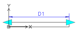
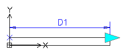
When you add an element to a CustomBlock definition, grip points appear at the main points of the element (points that you can use to manipulate the Block reference). Changing the grip point position does not affect the link with the main point. Moving the grip point in the Block reference affects the main point to which it is linked.
Make sure to correctly place the grip points in the CustomBlock definition to avoid potential confusion and unwanted results.
Example:
In the following example, a linear element defines a grip point. The move activity associates the grip point with the right circle and the end point of the element, which is the center of the circle.
Changing the grip point location in the CustomBlock definition does not affect the link with the main point (the center of the circle). In the Block reference, moving the grip point moves the right circle.
-
Grip point at the main point position
Moving the grip point in the Block reference moves the circle.
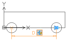
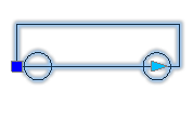
-
Grip point in a different position
Moving the grip point in the Block reference moves the circle.
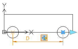
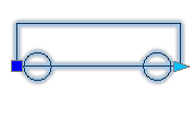
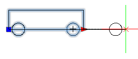
Specifying Insertion Cycling for Grip Points
Any grip point from the CustomBlock definition may become an insertion point in the Block reference. Use the CBCycleOrder command to specify the grip points that you can use as insertion points and their order in the list.
Pressing Ctrl key when inserting a CustomBlock with multiple insertion points lets you insert the Block from multiple position. However, the basepoint position does not change.
Specifying Value Sets for CustomBlocks
Use value sets to restrict an element to certain values when you insert a Block reference in a drawing.
You can specify a value set for these elements:
- Linear
- Polar
- Rotation
There are two methods to specify value sets:
- As a list of values
- As increments within a specified range.
Example:
In this example, you have a Custom Block defined to draw rectangular tables of various lengths. To limit the values, do one of the following:
- Specify a list of values for the length: 100, 120, 140 and 150 mm.
- Specify a range of values (from 100 .. 160) and an increment of 20. You can stretch the table to only 100, 120, 140, and 160mm.
To specify a value set for an element:
- Open the CustomBlock in the Block Editor.
- In the graphics area, specify the element.
- In the Properties palette, under Value Set, select an option:
-
Increment. Specify the increment and the range of values:
- Increment. The difference between the values in the sequence.
- Initial value. First value in the sequence.
- End value. The last value in the sequence.
-
List. Click
 to specify the list of values in the Value Set List dialog box.
- To add a specified value, click Add.
- To delete a value, select it from the list and click Delete.
-
Increment. Specify the increment and the range of values:
Adding Elements to CustomBlock Definitions
Use the CBElement command to add elements to CustomBlocks entities that you want to modify.
An element specifies additional properties and grip points for the CustomBlock that you can customize outside the Block Editor. Once you have added the element, you must apply an activity to it.
Examples:
- Add a point element to a point you want to move.
- Add a linear element to a line that you want to stretch.
To add an element:
- In the Block Editor, type CBElement at the command prompt.
- Specify an option:
- Point. Specifies X and Y properties for the Block reference. The position of the point element in the CustomBlock definition becomes the grip point position in the Block reference.
- Linear. Specifies the distance between two points in the CustomBlock definition. The specified points in the CustomBlock definition determine the grip points position in the Block reference.
- Polar. Specifies a distance and an angle for two points in the CustomBlock definition.
- XY. Specifies the X and Y distance from the base point of the CustomBlock definition.
- Rotation. Specifies an angle for the CustomBlock reference.
- Alignment. Specifies an alignment axis and a grip point in the CustomBlock definition. This lets you align the Block reference using the grip point.
- Mirror. Specifies the position of a mirroring axis and a grip point in the CustomBlock definition. This lets you mirror the Block reference using the grip point.
- Visibility. Adds a visibility element to the CustomBlock definition. In the Block reference, this grip point lets you select visibility states.
- Table. Adds a table element to the CustomBlock definition.
- Basepoint. Specifies a base point element for the CustomBlock definition.
The options correspond to the choices provided by individual element commands from the Block Editor.
- Optionally, specify the element properties. The set of properties corresponds to the element you add.
After you add the element, you can modify the element properties at any time in the Properties palette.
- Follow the command prompts.
The subsequent sequences of the CBElement command are identical to those of the individual command variants.
From the list of options above, click a link to see the command sequences.
CustomBlock Element Properties
The Properties palette groups the following properties of the CustomBlock elements:
Note: The set of properties displayed in the Properties palette corresponds to the element specified in the graphics area.
Name
Specifies a custom name of the element. The name does not appear in the Properties palette.
Label
Specifies the label that identifies the element in the graphics area and in the Properties palette (if you specified so). By default, elements have a generic label that you can modify.
Chain
Specifies whether you want to include the element in the selection set of an activity that is associated with a different element.
Description
Specifies an additional description of the label. When you select the element label in the Properties palette, this description displays at the bottom.
Base
Specifies whether you want to add a base point to the element.
Palette
Specifies whether you want to display the element in the Properties palette (Yes/No).
Value Set
Specifies a set of values that you can assign to the element in the Block reference.
- List. Specifies a list of values that are available for the element in the Block reference.
- Increment. Specifies minimum and maximum value and an increment.
Access
Command: CBElement
Adding a Point Element
Use the CBElement command with the Point option to define one grip point on an entity that you want to move or stretch.
To add a point element:
- Type CBElement at the command prompt.
- Specify the Point option.
- Optionally, specify the properties:
- Name
- Label
- Description
- Palette
You can always modify the element properties later in the Properties palette. - In the graphics area, specify the element position in the CustomBlock definition. The position of the point element in the CustomBlock definition becomes the grip point position in the Block reference.
- Specify the label location.
- Specify the number of grip points:
- 0. No grip points.
- 1. One grip point at the point position.
Access
Command: CBElement
Ribbon: Edit Block > Elements > Point
Adding a Linear Element
Use the CBElement command with the Linear option to add a linear element to a CustomBlock definition.
A linear element specifies the distance between two main points from the CustomBlock definition. The main points will determine the grip point positions on the Block reference.
To add a linear element:
- Type CBElement at the command prompt.
- Specify the Linear option.
- Optionally, specify the properties:
- Name
- Label
- Chain
- Description
- Base
- Palette
- Value set
You can always modify the element properties in the Properties palette. - In the graphics area, specify the main points of the element.
- Spcify the label location in the CustomBlock definition.
- Specify the number of grip points to appear in the Block reference:
- 0. No grip points.
- 1. One grip point at the endpoint of the element.
- 2. A grip point at the start point and endpoint.
Access
Command: CBElement
Ribbon: Edit Block > Elements > Linear
Adding a Polar Element
Use the CBElement command with the Polar option to add a polar element to a CustomBlock definition.
A polar element specifies the distance between two main points of the CustomBlock definition and displays an angle value.
To add a polar element:
- Type CBElement at the command prompt.
- Specify the Polar option.
- Optionally, specify the properties:
- Name
- Label
- Chain
- Description
- Base
- Palette
- Value set
You can always modify the element properties in the Properties palette. - In the graphics area, specify the main points of the element.
- Specify the label location in the CustomBlock definition.
- Specify the number of grip points to appear in the Block reference:
- 0. No grip points.
- 1. One grip point at the endpoint of the element.
- 2. A grip point at the start point and endpoint.
Access
Command: CBElement
Ribbon: Edit Block > Elements > Polar
Adding an XY Element
Use the CBElement command with the XY option to add an XY element to a CustomBlock definition.
An XY element specifies the X and Y properties for the Block reference.
To add an XY element:
- Type CBElement at the command prompt.
- Specify the XY option.
- Optionally, specify the properties:
- Name
- Label
- Chain
- Description
- Palette
- Value set
You can always modify the element properties in the Properties palette. - In the graphics area, specify the main points of the element.
- Specify the labels location in the CustomBlock definition.
- Specify the number of grip points to appear in the Block reference:
- 0. No grip points.
- 1. A grip point at the endpoint of the element.
- 2. A grip point at the base point and endpoint.
- 4. Grip points at all four corners of the element.
Access
Command: CBElement
Ribbon: Edit Block > Elements > XY
Adding a Rotation Element
Use the CBElement command with the Rotation option to add a rotation element to a CustomBlock definition.
A rotation element specifies an angle property for the Block reference. The software adds the grip point at the specified angle.
You can add only one grip point at the specified angle to the element.
To add a rotation element:
- Type CBElement at the command prompt.
- Specify the Rotation option.
- Optionally, specify the properties:
- Name
- Label
- Chain
- Description
- Palette
- Value set
You can always modify the element properties in the Properties palette. - In the graphics area, specify the base point.
- Specify the radius of the element.
- Specify the rotation angle.
- Specify the position of the label in the CustomBlock definition.
- Specify the number of grip points to appear in the Block reference:
- 0. No grip points.
- 1. One grip point at the endpoint of the element.
Access
Command: CBElement
Ribbon: Edit Block > Elements > Rotation
Adding an Alignment Element
Use the CBElement command with the Alignment option to add an alignment element to a CustomBlock definition.
An alignment element specifies an alignment direction for the CustomBlock.
In the Block Editor, the alignment element specifies an axis and a grip point. You can add only one grip point to the element.
You can use the grip point to align the Block reference with another entity in the drawing by automatically rotating the Block reference around the base point.
Note: An alignment element needs no associated activity.
To add an alignment element:
- Type CBElement at the command prompt.
- Specify the Alignment option.
- Optionally, specify the Name property.
You can always modify the element name in the Properties palette.
- In the graphics area, specify the base point of alignment.
The base point position in the CustomBlock definition specifies the alignment grip point position in the CustomBlock reference.
- Optionally, specify the alignment type:
- Perpendicular. Aligns entities of the CustomBlock reference perpendicularly with other entities in the drawing.
- Tangent. Aligns entities of the CustomBlock reference tangentially with other entities in the drawing.
- Specify the alignment direction.
Access
Command: CBElement
Ribbon: Edit Block > Elements > Alignment
Adding a Mirror Element
Use the CBElement command with the Mirror option to add a mirror element to the CustomBlock definition.
In the Block Editor, the mirror element specifies an axis and a grip point. You can mirror the Block reference about this axis using the grip point.
To add a mirror element:
- Type CBElement at the command prompt.
- Specify the Mirror option.
- Optionally, specify the properties:
- Name
- Label
- Description
- Palette
You can always modify the element properties in the Properties palette. - In the graphics area, specify two points to define the mirroring axis.
- Specify the label location in the CustomBlock definition.
- Specify the number of grip points to appear in the Block reference:
- 0. No grip points.
- 1. One grip point at the midpoint of the element.
Access
Command: CBElement
Ribbon: Edit Block > Elements > Mirror
Adding a Visibility Element
Use the CBElement command with the Visibility option to add a visibility element to a CustomBlock definition.
Note: A CustomBlock definition can contain only one visibility element.
To add a visibility element:
- Type CBElement at the command prompt.
- Specify the Visibility option.
- Optionally, specify the properties:
- Name
- Label
- Description
- Palette
You can always modify the element properties in the Properties palette. - In the graphics area, specify the element position in the CustomBlock definition. This determines the position of the element grip point in the Block reference.
- Specify the number of grip points.
- 0. No grip points.
- 1. One grip point at the element position.
The tools for defining visibility states are enabled.
Access
Command: CBElement
Ribbon: Edit Block > Elements > Visibility
Adding a Table Element
Use the CBElement command with the Table option to add a table element to a CustomBlock definition.
A table element lets you specify a custom property associated with a list of defined values.
Note: A CustomBlock definition can contain multiple table elements.
You can associate a table element with only one grip point. In the Block reference, clicking the grip point displays the list of available values.
To add a table element:
Note: Before adding any table element, make sure that you added the appropriate elements and activities.
- Type CBElement at the command prompt.
- Specify the Table option.
- Optionally, specify the properties:
- Name
- Label
- Description
- Palette
You can always modify the element properties in the Properties palette. - In the graphics area, specify the element position in the CustomBlock definition. The position of the table element in the CustomBlock definition is the grip point position in the Block reference.
- Specify the number of grip points:
- 0. No grip points.
- 1. One grip point will appear at the element position.
Access
Command: CBElement
Ribbon: Edit Block > Elements > Table
Adding a Base Point Element
Use the CBElement command with the Base option to define one base point for the CustomBlock reference relative to the CustomBlock geometry.
Note: A CustomBlock definition can contain only one base point element.
You cannot associate activities to a base point element. However, you can include the base point in the selection set of an activity. For example, you can include the base point in the selection set of a move activity to specify that the base point should follow the move activity.
To add a base point element:
- Type CBElement at the command prompt.
- Specify the Base option.
- In the graphics area, specify the element position in the CustomBlock definition. The position of the base point element in the CustomBlock definition is the grip point position in the Block reference.
Access
Command: CBElement
Ribbon: Edit Block > Elements > Basepoint
Applying Activities to CustomBlock Definitions
Activities are associated to elements and define how the entities of the CustomBlock reference change when you manipulate the Block reference in the drawing.
This section discusses:
- Using Activities
- Applying Available Activities to a Specified CustomBlock Element
- Applying Activities to CustomBlock Elements
Using Activities
Activities are associated to elements and define how the entities of the CustomBlock definition change when you manipulate the CustomBlock reference in the drawing.
When adding an activity to a CustomBlock definition, you need to specify the following:
- The element to which you want to apply the activity
Note: You can apply activities to elements only. You cannot apply activities to CustomBlock entities.
- A main point on the specified element
A main point lets you manipulate the Block reference.
- A selection set
A selection set consists of the entities that move or change when the activity occurs in the Block reference.
Activities display their icon plus this bolt icon  . Clicking the activity icon displays the selection set.
Elements that do not have associated activities display this icon ![]() . Double-clicking the warning icon
. Double-clicking the warning icon ![]() displays the activities that you can associate to the element.
displays the activities that you can associate to the element.
Use the CBActivityIcon command to display or hide the activity icons in the Block Editor. See Turning Activity Icons On and Off.
You can apply multiple activities to an element. The software groups all activities into an Activity toolbar.
Hovering the mouse cursor over an activity icon highlights the following:
- The related element
- The element grip point that lets you perform the activity
- The stretch frame (For stretch activities only). In a Block reference, moving the grip point affects only the entities in the stretch frame.
Note: The activity icon does not appear in the Block reference.
Example:
Hovering over a Stretch activity highlights the following:
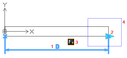 |
|
The software groups activities according to the elements that can use them.
Block Editor activities and associated elements:
| Activity | Icon | Transformation | Available elements |
|---|---|---|---|
| Move | Applies translation | Point, Linear, Polar, XY | |
| Scale | Applies scaling | Linear, Polar, XY | |
| Stretch | Stretches entities using stretch points from the specified area | Point, Linear, Polar, XY | |
| Polar Stretch | Applies stretching and rotation | Polar | |
| Rotate | Applies rotation | Rotation | |
| Mirror | Applies mirror transformation | Mirror | |
| Pattern | Creates entities across element directions with the specified offset. For an XY element, the pattern uses the X and Y directions. | Linear, Polar, XY | |
| Table | Applies the value set to other elements | Table |
Applying Available Activities to a Specified CustomBlock Element
Use the CBActivity command to apply activities to CustomBlocks elements.
Example:
- Add a stretch activity to a linear element you want to extend.
To apply available activities to a specified CustomBlock element:
- Type CBActivity at the command prompt.
- In the graphics area, specify the element to which to apply the activity.
- Specify the activity to apply to the specified element. The available activities depend on the type of element.
Element Available activities Point Move, Stretch Linear Move, Stretch, Scale, Pattern Polar Move, Stretch, Scale, Pattern, Polar XY Move, Stretch, Scale, Pattern Rotation Rotate Mirror Mirror Table Table - Follow the command prompts.
The subsequent sequences of the CBActivity command are identical to those of the individual command variants.
From the list of available activities above, click a link to see the command sequences.
Access
Command: CBActivity
Ribbon: Edit Block > Activities
Applying Activities to CustomBlock Elements
Use the CBActivityTool command to apply activities to elements in a CustomBlock definition.
To apply an activity to a CustomBlock element:
- Type CBActivityTool at the command prompt.
- Specify the activity:
Activity Applied to Current CustomBlock Definition Available elements Pattern Linear, Polar, XY Table Table Mirror Mirror Move Point, Linear, Polar, XY Rotate Rotation Scale Linear, Polar, XY Stretch Point, Linear, Polar, XY Polar Stretch Polar - In the graphics area, specify the element to which to apply the activity. The elements you can select depend on the type of the specified activity per the table above.
- Follow the command prompts.
The subsequent sequences of the CBActivityTool command are identical to those of the individual command variants. From the list of activities above, click a link to see the command sequences.
Access
Command: CBActivityTool
Applying Move Activities
Use Move activities to move entities with a specified distance and angle.
To define a move activity within a CustomBlock definition, you must apply the activity to an element and associate it with a selection set of CustomBlock entities.
You can apply a Move activity to the following elements:
-
Point. Moves the entities from the selection set in any direction.
The point element defines the grip point position for the move activity in the Block reference.
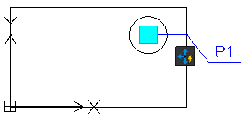
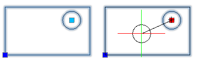
-
Linear. Moves the entities from the selection set only in the direction specified by the linear element.
The linear element defines the number of grip points for the move activity as well as their position in the Block reference.
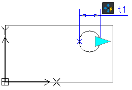
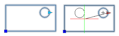
-
Polar. Moves the entities from the selection set in any direction.
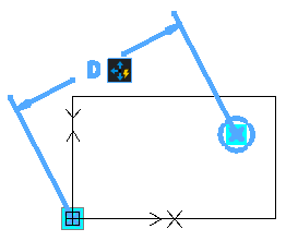
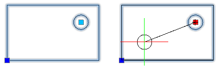
-
XY. Moves the entities from the selection set in the X, Y, or XY direction specified by the element.
The XY element defines the number of grip points for the move activity as well as their position in the Block reference.
To apply a move activity to a CustomBlock definition:
- In the Block Editor, type CBActivityTool at the command prompt.
- Specify the Move option.
- In the graphics area, specify one of the following elements to associate with the activity:
- Point
- Linear
- Polar
- XY
- Specify an element main point to associate with the move activity.
- Select the entities to associate with the activity and press Enter.
The activity icon displays on the specified element.
Applying Scale Activities
Use Scale activities to resize a set of Block entities relative to the base point specified by the activity.
You can apply a Scale activity to the following elements:
-
Linear. Scales the specified entities in the direction of the element.
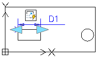
- Polar. Scales the specified entities by the specified distance and angle.
- XY. Scales the specified entities only in the X and Y directions specified by the element.
Scale Activity Base Point
You can specify whether the base point of the Scale activity coincides with the main point of the element to which the activity is applied or is an independent point specified in the CustomBlock definition.
The Base type property specifies the type of base point:
- Dependent. The base point of the Scale activity coincides with the main point of the element with which the Scale activity is associated. The entities from the selection set scale relative to the main point of the element.
- Independent. Lets you specify an independent base point by picking a fixed location in the drawing. Use the grip point to change the base point location.
Example
The following Block definition contains a Linear element and a Scale activity. The Linear element main point is the left point of the diameter.
- If the Base Type is Dependent, the Scale activity scales the circle relatively to the left point of the diameter.
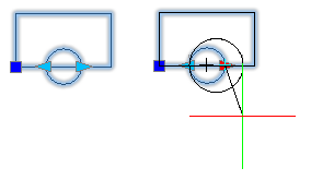
- If the Base Type is Independent, the Scale activity scales the circle relatively to a specified point. For example, you can scale the circle relatively to its center.
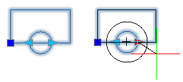
To apply a scale activity to a CustomBlock definition:
- In the Block Editor, type CBActivityTool at the command prompt.
- Specify the Scale option.
- In the graphics area, specify one of the following elements to associate with the scale activity:
- Linear
- Polar
- XY
- Select the entities to associate with the activity and press Enter.
The activity icon displays on the specified element.
Applying Stretch Activities
Use Stretch activities to move and stretch selected entities with a specified distance in the direction specified by the element.
You can apply a Stretch activity to the following elements:
-
Point. Moves and stretches the entities from the selection set by a specified distance in any direction.
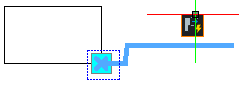
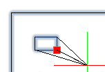
-
Linear. Moves and stretches the entities from the selection set by a specified distance in the direction specified by the linear element.
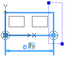
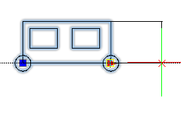
- Polar. Moves and stretches the entities from the selection set with a specified distance in the direction specified by the element.
-
XY. Moves and stretches the entities from the selection set in the X and Y directions specified by the element.
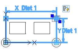
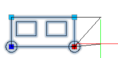
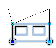
When associating a stretch activity with an element, you need to specify the stretch frame and the entities to include in the stretch activity.
The stretch frame specifies the part of the geometric entity to include in the activity.
- Entities that lie completely within the stretch frame are moved.
Example: In the picture below, the right circle lies completely within the stretch frame and therefore moves along with the grip point.
- Entities included in the selection set whose outlines intersect the stretch frame are stretched.
Example: In the picture below, the big rectangle intersects the stretch frame. Moving the grip point stretches the rectangle.
- Entities not included in the selection set, are not affected, regardless of whether they are within or crossed by the stretch frame.
Example: In the picture below, the left rectangle is outside the selection set. Moving the grip point does not change the left rectangle position.
- Entities outside the stretch frame and included in the selection set are moved.
Example: In the picture below, the right rectangle is part of the selection set. Moving the grip point moves the right rectangle as well.
Example:
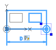
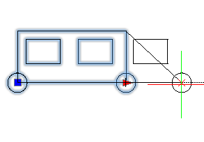
To apply a stretch activity to a CustomBlock definition:
- In the Block Editor, type CBActivityTool at the command prompt.
- Specify the Stretch option.
- In the graphics area, specify one of the following elements to associate with the activity:
- Point
- Linear
- Polar
- XY
- Specify an element main point to associate with the stretch activity.
- Specify the first corner of the stretch frame.
- Specify the opposite corner of the stretch frame.
- Select the entities to associate with the activity and press Enter.
The activity icon appears on the specified element.
Applying Polar Stretch Activities
Use Polar Stretch activities to move, stretch, and rotate the entities from the selection set with a specified angle and distance.
You can apply a Polar Stretch activity only to polar elements. The polar stretch activity lets you stretch the entities from the selection set at any angle.
When associating a polar stretch activity with an element, you need to specify the stretch frame for the polar stretch activity, the entities to stretch, and the entities to rotate.
- Entities that lie completely within the stretch frame are moved.
- Entities included in the selection set whose outlines intersect the stretch frame are stretched. Entities specified for rotate only in the activity’s selection set are not stretched.
- Entities not included in the selection set are not affected, regardless of whether they are within or crossed by the stretch frame.
- Entities outside the stretch frame and included in the selection set are moved.
Example:
In the following example, the rectangle is selected for stretching and the circle for rotation only.
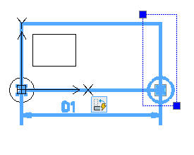

To apply a polar stretch activity to a CustomBlock definition:
- In the Block Editor, type CBActivityTool at the command prompt.
- Specify the Polar Stretch option.
- In the graphics area, specify the polar element to associate with the activity.
- Specify the element point to associate with the activity.
- Specify the first corner of the stretch frame.
- Specify the second corner of the stretch frame.
- Specify the entities to stretch and press Enter.
- Specify the entities to rotate only and press Enter.
The activity icon displays on the specified element.
Applying Rotate Activities
Use Rotate activities to rotate entities from the selection set.
You can apply a Rotate activity only to a Rotation element.
Note: During Block definition, you can choose any point as the rotation base point.
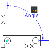
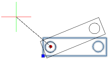
Rotate Activity Base Point
You can specify whether the base point of the Rotate activity coincides with the main point of the Rotation element or is an independent point.
The Base Type property specifies the type of base point:
- Dependent. The base point of the Rotation activity is the Rotate element main point. The entities from the selection set rotate around the Rotate element main point. Moving the main point of the Rotate element, changes the Rotation base point location. Dependent base point has no grip point.
- Independent. Lets you specify an independent base point by picking a fixed location in the CustomBlock reference. Use the grip point to change the base point location.
Example
The following Block represents a table and six chairs. The Block definition contains a Rotation element and a Rotate activity. The Rotation element main point is in the center of the table.
- If the Base Type is Dependent, the Rotation activity rotates entities around the center of the table.

- If the Base Type is Independent and the independent base point is the lower left corner of the table. Thus, the table and the chairs rotate around the lower left corner.
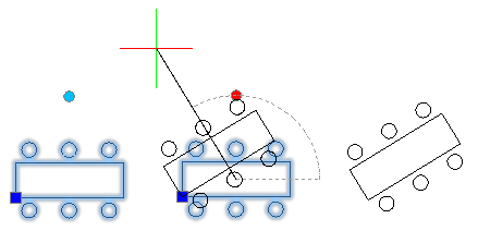
To apply a rotate activity to a CustomBlock definition:
- In the Block Editor, type CBActivityTool at the command prompt.
- Specify the Rotate option.
- In the graphics area, specify a rotate elements to associate with the activity.
- Select the entities to associate with the activity and press Enter.
The activity icon displays on the specified element.
Applying Mirror Activities
Use Mirror activity to flip entities from the selection set in the direction specified by the flip element.
Only the entities from the selection set mirror about the reflection line.
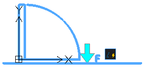
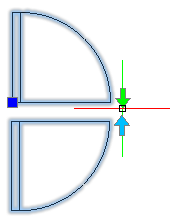
To apply a mirror activity to a CustomBlock definition:
- In the Block Editor, type CBActivityTool at the command prompt.
- Specify the Mirror option.
- In the graphics area, specify a mirror element to associate with the activity.
- Specify the entities to associate with the activity and press Enter.
The activity icon displays on the specified element.
Applying Pattern Activities
Use Pattern activities to copy entities in the direction specified by the element. Specify the offset distance.
A pattern activity creates a pattern when you trigger the activity in the CustomBlock reference, which uses the selection set of entities in the pattern.
You can apply a Pattern activity to the following elements:
-
Linear.
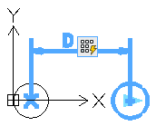
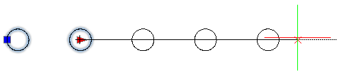
- Polar.
-
XY.
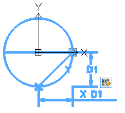
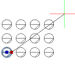
To add a pattern activity to a CustomBlock definition:
- In the Block Editor, type CBActivityTool at the command prompt.
- Specify the Pattern option.
- In the graphics area, specify one of the following elements to associate with the activity:
- Linear
- Polar
- XY
- Specify the entities to associate with the activity and press Enter.
- Specify the offset distance between columns.
- If you are applying the pattern activity to an XY element, specify the distance between rows.
The activity icon appears on the specified element.
Applying Table Activities
Use Table activities to associate sets of values to elements of a CustomBlock definition.
Note: You can apply a table activity only to table elements.
Associating a table activity to a table element creates an empty value table. Use the CBValueTable command to add properties and value sets to the value table.
To apply a table activity:
- In the Block Editor, type CBActivityTool at the command prompt.
- Specify the Table option.
- In the graphics area, specify a table element.
The activity icon appears on the specified element.
To add properties and values to the value table, use the CBValueTable command. Alternatively, click the activity icon in the graphics area and click in the Properties palette. The Property Value Table dialog box displays the value table.
Using Element Sets
Element sets are predefined sets of elements and activities that can be used together. An element set places an element along with an associated activity to each grip point of the element.
The following table lists the element set available in the Block Editor.
| Element Set | Description |
|---|---|
| Point Move | Adds a point element with one grip point and a move activity |
| Linear Move | Adds a linear element with one grip point and a move activity |
| Linear Stretch | Adds a linear element with one grip point and a stretch activity |
| Linear Pattern | Adds a linear element with one grip point and a pattern activity |
| Linear Move Pair | Adds a linear element with two grip points and a move activity linked to each grip point |
| Linear Stretch Pair | Adds a linear element with two grip points and a stretch activity linked to each grip point |
| Polar Move | Adds a polar element with one grip point and a move activity |
| Polar Stretch | Adds a polar element with one grip point and a stretch activity |
| Polar Pattern | Adds a polar element with one grip point and a pattern activity |
| Polar Move Pair | Adds a polar element with two grip points and a move activity linked to each grip point |
| Polar Stretch Pair | Adds a polar element with two grip points and a stretch activity linked to each grip point |
| XY Move | Adds an XY element with one grip point and a move activity |
| XY Move Pair | Adds an XY element with two grip points and a move activity linked to each grip point |
| XY Move Box Set | Adds an XY element with four grip points and a move activity linked to each grip point |
| XY Stretch Box Set | Adds an XY element with four grip points and a stretch activity linked to each grip point |
| XY Pattern Box Set | Adds an XY element with four grip points and a pattern activity linked to each grip point |
| Rotation Set | Adds a rotation element with one grip point and a rotation activity |
| Mirror Set | Adds a mirror element with one grip point and a mirror activity |
| Visibility Set | Adds a visibility element with one grip point |
| Table Set | Adds a table element with one grip point and a table activity |
Access
Command: CBElementSet
Controlling the Visibility of CustomBlocks Entities
You can modify the set of entities displayed in a CustomBlock reference using visibility elements and visibility states.
This section discusses:
- About Visibility States
- Managing Visibility States
- Adding Entities to a Visibility State
- Hiding Entities from a Visibility State
About Visibility States
You can modify the set of entities displayed in a CustomBlock reference using visibility elements and visibility states.
A visibility state is a property of the CustomBlock that specifies which entities of the CustomBlock appear in the Block reference.
For example, you can use a single CustomBlock with two visibility states (V1 and V2) to represent rectangular and round tables. Each visibility state displays the corresponding geometry, as follows:
- V1 displays the circle
- V2 displays the rectangle.
At creation time, a Block reference displays the entities from the default visibility state. You can use the visibility grip point to specify another visibility state.
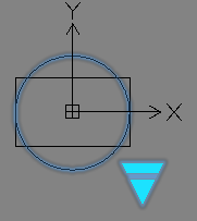
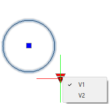
Managing Visibility States
Use the CBVisibility command to manage visibility states of a CustomBlock definition.
To define a new visibility state in a CustomBlock definition:
Note: Before defining any visibility state, make sure that the visibility element exists in the CustomBlock definition.
- Do one of the following:
- Type CBVisibility.
- Double-click a visibility element.
- In the Visibility States dialog box, click New.
- In the dialog box, do the following:
- Type the name of the visibility state.
- Specify an option:
- Hide all existing entities in new state
- Show all existing entities in new state
- Use visibility of existing entities from the active state.
- Click OK.
In the Visibility States dialog box, the new visibility state appears in the list.
- Click OK.
The Visibility States drop-down list displays all defined visibility states.
To rename or delete a visibility state from a CustomBlock definition:
- In the Block Editor, do one of the following:
- Type CBVisibility.
- Double-click a visibility element.
- In the Visibility States dialog box, specify the visibility state to rename or to delete.
- Click Rename or Delete.
To specify the default visibility state for a CustomBlock:
Note: The default visibility state is the first one in the Visibility States list.
- In the Block Editor, do one of the following:
- Type CBVisibility.
- Double-click a visibility element.
- In the Visibility States dialog box, specify a visibility state from the list.
- Click Move Up until the specified visibility state is the first in the list.
To specify the current visibility state:
- In the Block Editor, do one of the following:
- Type CBVisibility.
- Double-click a visibility element.
- In the Visibility States dialog box, specify a visibility state.
- Click Activate.
To specify the set of entities for a visibility state:
- In the Block Editor, do one of the following:
- Type CBVisibility.
- Double-click a visibility element.
- In the Visibility States dialog box, specify the active visibility state.
- Click OK.
- Do one of the following:
Access
Command: CBVisibility
Ribbon: Edit Block > Display State > Visibility States
Adding Entities to a Visibility State
Use the CBShow command to specify the entities to display in a visibility state.
To add entities to a visibility state:
- In the Block Editor, specify the active visibility state.
- Type CBShow at the command prompt.
The entities visible in the active visible state are highlighted.
- In the graphics area, specify the entities to display.
- Press Enter.
Access
Command: CBShow
Ribbon: Edit Block > Display State > Show
Hiding Entities from a Visibility State
Use the CBHide command to specify the entities to hide from a visibility state.
To specify the entities to hide from a visibility state:
- In the Block Editor, specify the active visibility state.
- Type CBHide at the command prompt.
The entities hidden from the active visible state are highlighted.
- In the graphics area, specify the entities to hide.
- Press Enter.
Access
Command: CBHide
Ribbon: Edit Block > Display State > Hide
Associating Data to CustomBlocks
You can use value tables to associate a list of custom property values to a CustomBlock.
This section discusses:
About Value Tables
A value table associates a list of CustomBlock properties and their corresponding values to a description. The properties define the column headings and each row defines a value state.
In the Block reference, you can display the list of available descriptions by clicking the table grip point. Selecting a description automatically changes the Block reference to the corresponding values defined by the rows in the value table.
Associating a table activity to a table element creates an empty value table. You need to add the required properties to the table and specify the values in each cell.
You can click a cell and type a value. If you specified a value set for an element, then you can select the value from a drop-down list.
To display the value table associated to a table activity, use the CBValueTable command.
There are two types of properties:
- Input properties: CustomBlock elements, other than table elements.
- Table properties: Table elements.
The value table uses the element label as column title and property
Example:
Considering a CustomBlock defined for representing desks of various lengths and widths, instead of stretching using a grip point, you can select the values from a list of specific sizes. A value table defines the list of values using Length and Width columns.
| Length | Width | Table 1 States |
|---|---|---|
| 100 | 50 | D1 (100 x 50) |
| 200 | 150 | D2 (200 x 150) |
Selecting the corresponding table element grip point in the Block reference displays the list of available descriptions (states). To change the size of the Block reference, select an option from the list. The Properties palette displays the corresponding values for Length and Width (Custom category). The grip point for the stretch activity is not required in this case.
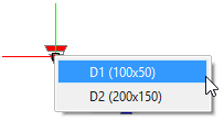
Defining Value Tables for CustomBlock Definitions
Use the CBValueTable command to display or update the value table associated to a table activity in a CustomBlock definition.
You can add properties and values to the value table.
To display or update a value table for a table activity:
Note: Make sure that the CustomBlock definition contains at least one table element that has an associated table activity. Associating a table activity to a table element creates an empty value table.
- In the Block Editor, type CBValueTable at the command prompt.
- In the graphics area, specify a table element.
The Property Value Table dialog box displays the existing value table for the specified table activity.
You can do the following:
- Click OK.
To add properties to the value table:
- In the Property Value Table dialog box, click Add Properties.
- In the Add Element Properties dialog box, do the following:
- Specify the type of property to add to the table:
- Add input properties. The element properties list displays the available input properties that you can add to the table.
- Add table properties. The element properties list displays the available table properties that you can add to the table.
- From the list, select an element and click OK to add it to the table.
The corresponding column appears in the table.
- Specify the type of property to add to the table:
- Repeat step 1 and 2 to add more properties and to complete the table.
To add values to a value table:
- In the Block Editor, type CBValueTable at the command prompt.
- In the graphics area, specify a table element.
The Property Value Table dialog box displays the value table defined for the associated table activity.
- In the States column, type the name of each value state.
- Click an empty cell.
- Do one of the following:
- Enter a value.
- Specify a value from the drop-down list.
Note: Drop-down lists are available only if the element has a value set.
- Repeat step 4 and 5 as necessary to complete the table.
- Click OK.
To delete value states from the value table:
- In the Property Value Table dialog box, select the lines corresponding to the value state to delete.
- Click Delete.
To check for errors a value table:
- In the Block Editor, type CBValueTable at the command prompt.
- In the graphics area, specify a table element.
- In the Property Value Table dialog box, click Check.
Access
Command: CBValueTable
Defining Properties Tables for CustomBlock Definitions
A Block properties table associates combinations of values to Block properties. For example, you can use a Block properties table to define a set of dimensions for doors.
In the Block reference, you can display the list of available combinations of values by clicking the table grip point. Selecting a combination of values automatically changes the Block reference to the corresponding values defined by the rows in the Block properties table.
Use the CBTable command to display or update the Block properties table associated to a CustomBlock definition.
The command creates an empty Block properties table.
You can add element properties and values to the Block properties table.
Each CustomBlock definition can have only one Block properties table.
The Block properties table can include:
- Elements
- User parameters
- Dimensional constraint parameters
- Attributes. Attributes let you name each row of the Block properties table.
Note: Assign the Predefined mode to attributes that you want to include in a Block properties table.
Example:
Considering a CustomBlock defined for representing windows of various sizes, you can select from a list of specific sizes.
Selecting the corresponding Block properties table element grip point in the Block reference displays the list of available sizes. To change the size of the window, for the corresponding Block reference, select an option from the list. The Properties palette displays the corresponding values for the window Length and Width (Custom category).
The workflow for defining a Block properties table includes the following steps:
- Open the Block Editor and create all necessary elements and attributes for the CustomBlock.
To create a Block properties table:
- Open the Block Editor and create all necessary elements and attributes for the CustomBlock.
- In the Block Editor, do one of the following:
- On the ribbon, select Edit Block > Dimensional > Block Table.
- Type CBTable.
- Optionally, specify the properties:
- Name
- Label
- Description
- Palette. Determines whether the label appears in the Properties palette when you select the Block reference.
You can always modify the element properties later in the Properties palette. - In the graphics area, specify the element position in the CustomBlock definition. The position of the properties table element in the CustomBlock definition becomes the grip point position in the Block reference.
- Specify the number of grip points:
- 0. No grip points.
- 1. One grip point at the point position.
- In the Block Properties Table dialog box, do the following:
-
In the Block Properties Table dialog box, a column appears for each element property.
- Type a value in each cell of the row.
A new row appears automatically when you type a value in a cell. Each row represents a new set of values. These sets of values appear in the context menu when you insert the Block and select the Block properties table parameter grip point.
Note: Right-clicking on a column heading displays a context menu with options for adjusting columns.
- Click
 to check each set of values in the Block properties table.
Note: Make sure the records are unique.
- Optionally, use Block properties must match a row in the table to specify whether the properties added to the table can be modified individually or not. When it is possible to change other properties without matching a row, the default properties are displayed.
- Click OK to return to the Block Editor.
To display again the Block Properties Table dialog box double-click the table element or access the CBTable command.
To add properties to the Block properties table:
- In the Block Properties Table dialog box, click Add Properties
 .
.
The Add Element Properties dialog box lists all elements in the Block that contain property values.
Note: The property name is the label of the element.
- Select element properties to add to the table.
Note: Use Shift and Ctrl for multiple selection.
- Click OK.
In the Block Properties Table dialog box, a column appears for each element property.
To add a new user parameter to a Block properties table:
- In the Block Properties Table dialog box, click Add Properties .
- In the Add Element Properties dialog box, specify the user element properties:
- Name. Specify the name of the user parameter.
- Value. Specify the value of the user parameter.
- Type. Defines the type of the new parameter.
- Select Display in Properties palette to display the user parameter as a property in the Properties palette for the Block reference.
- Click OK.
A new column appears in the table for the user parameter.
To remove properties from the Block properties table:
- In the Block Properties Table dialog box, select the column that corresponds to the property to delete.
- Right-click and select Delete Column.
Access
Command: CBTable
Ribbon: Edit Block > Dimensional > Block Table
Testing CustomBlocks
At any time, you can test a CustomBlock definition without exiting the Block Editor.
The CBTestBlock command displays the current Block definition in a test window.
You can make changes to the CustomBlock definition and test the effect without saving the CustomBlock definition.
The test window closes automatically when you close the Block Editor. Alternatively, use the CBTestClose command to close only the test window.
It is recommended to test the CustomBlock after each modification to prevent errors.
To test a CustomBlock:
- In the Block Editor, type CBTestBlock at the command prompt.
The corresponding Block reference appears in a test window.
- In the test window, select the CustomBlock reference and do the following:
- Test the grip points
- Test the CustomBlock behavior when changing the properties in the Properties palette
- Create additional copies
To close the test window:
- Type CBTestClose at the command prompt.
Access
Command: CBTestBlock
Ribbon: Edit Block > Save > Test Block
Modifying CustomBlock References
When you select a CustomBlock reference in the graphics area:
- Grip points of the defined elements display on the Block geometry
- Additional properties of the CustomBlock display in the Custom category, on the Properties palette.
Modifying CustomBlock References Using Custom Properties
When creating CustomBlock, you can use elements to specify custom properties for the CustomBlock. Additionally, you can choose to display these properties in the Properties palette when you select the CustomBlock reference in a drawing.
Distance Multiplier and Angle Offset Action Overrides
For some activities, the Overrides category of the Properties palette groups the following properties:
- Distance multiplier. Lets you specify a factor by which a distance value of an element is increased or decreased. For example, a distance multiplier of 2 for a stretch activity doubles the associated entities of the CustomBlocks when moving the grip point.
- Angle offset. Lets you specify a factor by which an angular value of an element is increased or decreased. For example, an angle offset of 60 for a move activity moves 60 degrees beyond the angle value when moving the grip point.
You can use distance multiplier and angle offset overrides with the following activities:
To specify a distance multiplier for an activity:
- In the Block Editor, specify one of the following activities:
- On the Properties palette, in the Overrides category, specify a value for the Distance Multiplier.
- Press Enter.
To specify an angle offset:
- In the Block Editor, specify one of the following activities:
- On the Properties palette, in the Overrides category, specify a value for the Angle offset.
- Press Enter.
Modifying CustomBlock References Using Grip Points
As you click or drag the grip points, entities in the Block reference adjust according to the activity that defines the modification.
The following grip points are available:
| Grip Type | Icon | Modifications |
|---|---|---|
| Standard | |
Moves, stretches, scales, or patterns entities independently in a Block reference. |
| Linear | |
Lengthens, stretches, scales, or patterns entities in a Block reference along a vector. |
| Rotation | |
Rotates entities in a Block reference around an axis. |
| Flip | |
Flips (mirrors) entities in a Block reference about an axis. |
| Table / Visibility | |
Changes forms or dimensions based on predefined lists. Also, controls the visibility of subsets of entities based on lookup lists. |
At any time, you can reset the Block reference using the ResetBlock command. The Block reference changes back to the default values specified in the CustomBlock definition.
To modify CustomBlock references:
- In the graphics area, select a CustomBlock reference.
- Click or drag grips.
- On the Properties palette, under Custom, edit CustomBlock elements.
To reset CustomBlock references:
- In the graphics area, right-click and specify the CustomBlock reference and select Reset Block.
Working with Dynamic Blocks
Using Dynamic Block Grips
When you select a Dynamic Block:
- Special grips display on the Block geometry
- Additional options for the Block display on the Properties palette
As you click or drag the grips, entities in the Block reference adjust according to the parameters that define the modification.
Each Dynamic Block grip has a label. The label displays in the Custom section of the Properties palette where you can modify values or select options.
Depending on the complexity of features and constraints within a Dynamic Block, more or less grips display to define how the Block reference should look like.
Grips available in Dynamic Block references are:
| Grip Type | Icon | Modifications |
|---|---|---|
| Standard | |
Moves, stretches, scales, or patterns entities independently in a Block reference. |
| Linear | |
Lengthens, stretches, scales, or patterns entities in a Block reference along a vector. |
| Rotation | |
Rotates entities in a Block reference around an axis. |
| Flip | |
Flips (mirrors) entities in a Block reference about an axis. |
| Alignment | |
Aligns entities of a Block reference with other entities in the drawing, either tangentially or perpendicularly. |
| Lookup | |
Changes forms or dimensions based on predefined lists. Also, controls the visibility of subsets of entities based on lookup lists. |
To work with Dynamic Block grips:
- In the graphics area, select a Dynamic Block reference.
- Click or drag grips.
- On the Properties palette, under Custom, edit Dynamic Block parameters.
Inserting Dynamic Blocks
Use the InsertBlock command to insert Dynamic Blocks that are defined in the current drawing. When you select a Block in the dialog box, an asterisk ![]() in the preview image identifies it as a Dynamic Block.
in the preview image identifies it as a Dynamic Block.
Use the References palette to insert Dynamic Blocks from external drawings.
Use the ExportDrawing command to write Dynamic Blocks to a drawing file for subsequent insertions in other drawings.
To insert Dynamic Blocks that are defined in the current drawing:
- Click Insert > Block (or type InsertBlock).
- In the dialog box, in Name, select a Dynamic Block.
An asterisk
in the lower right corner of the Preview image identifies a Block as a Dynamic Block. - In Position, Scale, and Rotate, specify the insertion parameters.
- In Block UnitSystem, clear Explode.
- Click OK.
To insert Dynamic Blocks from external drawings:
- In the References palette, in Folders, locate a drawing that contains a Dynamic Block.
- In Content, double-click Block.
- Click a Dynamic Block.
An asterisk
in the lower right corner of the Preview image identifies a Block as a Dynamic Block. - Do one of the following:
- Drag the Block into the graphics area.
- Right-click and click Insert Block. In the dialog box, specify the insertion parameters.
To circle through a set of base points when inserting a Dynamic Block:
- When you are prompted to specify the insertion point of the Block, press Ctrl until you see the preview you want.
The preview of the Block insertion updates in the graphics area with an alternate base points at the crosshair (pointer) position.
To write a Dynamic Block to a file:
- Click File > Export > Export Drawing (or type ExportDrawing).
- In the dialog box, under Source, select Block.
- From the list, select the Block to write to a file.
- Under Destination, specify a path and file name, or click Browse to locate a destination folder and enter a file name.
Converting Dynamic Blocks into CustomBlocks
Use the CBConvert command to convert dynamic blocks from a DWG file into CustomBlocks.
You can choose whether to delete or retain the original dynamic block.
To convert a dynamic block into a CustomBlock:
- Type CBConvert at the command prompt.
- In the Convert Block dialog box, specify the dynamic block to convert:
- Select a dynamic block from the drop-down list.
- Click Specify Block, select the dynamic blocks in the graphics area, and press Enter to complete the selection. The dialog box appears again when your selection is complete.
- Under the Block definition, specify an option:
- Replace existing block. Creates a CustomBlock based on the specified dynamic block definition and replaces the corresponding dynamic block instances with the new CustomBlock.
-
Create a copy. Creates the CustomBlock based on the specified dynamic block definition and keeps the original dynamic block in the drawing.
Note: If you want to convert the dynamic block instances, you must specify them.
- Optionally, click Open in Block Editor to open the CustomBlock in the Block Editor.
- Under Block instances, specify options:
-
Specify block instances. Lets you select dynamic block instances to convert.
Note: This option is available only if you choose to keep the dynamic block.
-
Replace all block instances. Replaces all instances of the specified dynamic block with the new CustomBlock.
Note: This option is available only if you choose to keep the dynamic block.
- Reset block instances. Resets all affected block instances to their initial state.
-
Specify block instances. Lets you select dynamic block instances to convert.
- Click OK.
Access
Command: CBConvert
Using Design Resources
Use the DesignResources command to access resources and contents from other drawings on your computer or network places to which you are connected. You can employ and import Blocks, Reference drawings, Layers, LineStyles, DimensionStyles, TextStyles, TableStyles, and layout Sheets into the current drawing.
From the Design Resources palette, you can drag and drop drawing contents, copy and paste them, and add, attach, or insert them. These procedures are discussed in Typical Procedures when Using Design Resources.
Additionally, you can add a set of Blocks on a tool palette in one step using the Design Resources. Options are available in context menus. Procedures are discussed in Using Blocks with Tool Palettes.
The palette contains two tabs:
- Computer: Displays resources and contents from your computer or network places to which you are connected.
- Opened files: Display contents from the opened drawings.
In addition, there is a toolbar at the top and a status bar at the bottom of the palette.
To show the Design Resources palette:
- Click Tools > Design Resources (or type DesignResources).
– or –
- Press Ctrl + 2.
Design Resources Palette
Computer tab
The palette contains three sections:
- Resources tree view: Browses the disks, folders, network drives, and drawing files.
- Content list: Displays the contents of the selected item in the Folders tree view.
- Preview area: Displays previews of drawing files, Blocks, References, and image files.
Folders tree view
The Resources tree view lets you navigate to folders and files on your computer, network places you are connected to, and your system Desktop.
These file types are listed in the tree view:
- Drawing file (*dwg)
- Drawing exchange file (*dxf)
- Drawing template file (*.dwt)
- Drawing standards file (*.dws)
If the folder you select contains image files, these are listed in the Content list.
Note: Hidden folders or files are not displayed in the Design Resources palette.
Content list
The Content list area displays the contents of the item you selected in the Resources tree view.
- If you selected a folder, Content displays drawings and images contained in the folder and subfolders.
Image files can be of type *.bmp, *.gif, *.jpg, *.png, and *.tif.
- If you selected a drawing file, Content displays a list of all categories of named objects contained in a drawing:
- Blocks
- Reference drawings
- Layers
- LineStyles
- DimensionStyles
- TextStyles
- TableStyles
- Sheets
Note: You can also show these categories in the Resources tree view by clicking the plus sign (+) in front of a drawing file (which expands the categories list).
Preview area
The Preview area displays previews of drawing files, Blocks, References, and images.
Toolbar
Use the buttons in the toolbar at the top of the Design Resources palette for navigation and access options:
-
Open
 : Opens a drawing or image file, sets the Resources tree view to the folder of that file, and highlights the file name in the Content list.
 -
Home
 : Displays the default folder or file you selected in the Resources tree view.
To set the Home position, in the Resources tree view, right-click an item and click Set as Home.
-
Favorites
 : Displays your favorite resources in the Favorites folder. You can bookmark resources you often use or want to quickly find.
To add folders or files to the Favorites folder in the Resources tree view, right-click an item and click Add to Favorites.
To remove folders or files from the Favorites folder, in the Content list, right-click an item and click Remove from Favorites.
Note: The Favorites folder is not a physical folder on your hard drive. It is a list of links to folders and files on your system.
-
Back
 : Displays the previously viewed folder or file.
Click the arrow to show the list of the recently browsed folders and files.
-
Forward
 : Displays the previously viewed folder or file if you clicked Back.
Click the arrow to show the list of folders and files from which you stepped back using the Back button.
-
Up
 : Moves one level up in the Resources tree view hierarchy.
 -
Tree View Toggle
 : Shows or hides the Folders tree view.
 -
Preview Toggle
 : Shows or hides the Preview area.
 -
Refresh
 : Refreshes the Resources tree view, Content list, and Preview area (for example, if changes were made externally to the selected folder).
 -
View
 : Changes the display of the Content list among list, details, thumbnails, and icons. Click the arrow to select one of these display modes.
Status bar
The status bar displays the full folder and file names of the selected item in the Resources tree view and the number of applicable items that are listed in the Contents list.
Opened Files tab
The palette contains three sections:
- Resources tree view: Browses the opened drawing files.
- Content list: Displays the contents of the selected item in the Resources tree view.
- Preview area: Displays previews of drawing files, Blocks, References, and image files.
Resources
The Resources tree view lets you navigate to opened files.
These file types are listed in the tree view:
- Drawing file (*.dwg)
- Drawing exchange file (*.dxf)
- Drawing template file (*.dwt)
- Drawing standards file (*.dws)
Content list
The Content list area displays the contents of the item you selected in the Resources tree view.
The Content list area displays a list of all categories of named objects contained in the drawing selected in the Resources tree view:
- Blocks
You can group all Blocks of a drawing on a tool palette using the Create Tool Palette option from the context menu.
- Reference drawings
- Layers
- LineStyles
- DimensionStyles
- TextStyles
- TableStyles
- Sheets
Note: You can also show these categories in the Resources tree view by clicking the plus sign (+) in front of a drawing file (which expands the categories list).
Preview area
The Preview area displays previews of the specified drawing file, Block, Reference, and image.
Typical Procedures when Using Design Resources
You can drag and drop drawing contents, copy and paste them, and add, attach, or insert them.
To drag content from other drawings to the graphics area:
- In the tree view, browse to a drawing file.
- In the Resources list, double-click a category (Blocks, Layers, LineStyles, DimensionStyles, TextStyles, TableStyles, Reference, or Sheets).
- In the Content list, drag an item from the list into the drawing.
- If you drag a Block or a Reference drawing, specify the position of the Block or Reference. If the Block contains BlockAttributes, edit the attributes.
To copy and paste content from other drawings into the drawing:
- In the tree view, browse to a drawing file.
Note: If you have already opened the drawing that contains Blocks, you can find it in the Opened files tree view.
- In the Resources list, double-click a category (Blocks, Layers, LineStyles, DimensionStyles, TextStyles, TableStyles, Reference, or Sheets).
- In the Content list, right-click an item and click Copy.
- In the graphics area, right-click and click Paste.
- If you paste a Block or a Reference drawing, specify the position of the Block or Reference.
To insert Blocks from other drawings into the drawing:
- In the tree view, browse to a drawing file that contains Blocks.
Note: If you have already opened the drawing that contains Blocks, you can find it in the Opened files tree view.
- In the Resources list, double-click the Blocks category.
- In the Content list, specify a Block.
The Block is displayed in the Preview area.
- Right-click and click Insert Block.
Note: If the specified Block has the same name as a Block used in the drawing, you can redefine existing Blocks using the following options:
- Insert and redefine: Inserts the specified Block and replaces existing Blocks with the Block specified in the Content list, if the existing Blocks have the same name as the specified one.
- Redefine only: Replaces existing Blocks with the Block specified in the Content list, if the existing Blocks have the same name as the specified one.
- In the Insert Block dialog box, specify options and values as if you use the InsertBlock command.
- Click OK.
To insert Blocks from Design Resources you can also double-click a Block in the Content list.
To redefine existing Blocks to a Block from another drawing:
- In the tree view, browse to a drawing file that contains Blocks.
- In the Resources list, double-click the Blocks category.
- In the Content list, specify a Block.
The specified Block is displayed in the Preview area.
- Right-click and click Redefine only.
Existing Blocks are replaced with the Block specified in the Content list.
Note: The Redefine only option is available only if you have already opened the drawing that contains Blocks.
To insert a Block from other drawing and redefine existing Blocks:
- In the tree view, browse to a drawing file.
- In the Resources list, double-click the Blocks category.
- In the Content list, specify a Block.
The Block is displayed in the Preview area.
- Right-click and click Insert and redefine.
Note: The Insert and redefine option is available only if you have already opened the drawing that contains Blocks.
- In the Insert Block dialog box, specify options and values as if you use the InsertBlock command.
- Click OK.
Existing Blocks are replaced with the Block specified in the Contents list.
To attach References from other drawings to the drawing:
- In the tree view, browse to a drawing file that contains a referenced drawing.
- In the Resources list, double-click the Reference drawings category.
- In the Content list, right-click a Reference and click Attach Reference.
- In the Attach Reference dialog box, specify options and values as if you use the AttachDrawing command.
- Click OK.
Attaching image files functions in a similar way.
To add Layers from other drawings to the drawing:
This procedure also works with LinesStyles, DimensionStyles, TextStyles, TableStyles, and layout Sheets.
- In the tree view, browse to a drawing file.
- In the Resources list, double-click the Layers category.
- In the Content list, select one or more Layer names, right-click and click Add Layers.
The Layers are added to the current drawing. Duplicate Layers are ignored.
To add a single Layer from Design Resources, you can double-click a Layer name in the Contents list.
To add layout Sheet definitions from other drawings to the drawing:
- In the tree view, browse to a drawing file.
- In the Resources list, double-click the Sheets category.
- In the Content list, select one or more Sheet names, right-click and click Add Sheets.
The Sheets are added to the current drawing. Duplicate Sheets are ignored.
To insert drawings as Blocks, attach drawings as References, or open drawings from the Design Resources palette:
- In the tree view, browse to a folder that contains at least one drawing file.
- In the Resources list, select a drawing file.
- Right-click and specify an option:
- Attach as Reference: Attaches the specified drawing file as if you used the AttachDrawing command.
- Insert as Block: Inserts the specified drawing file as if you used the InsertBlock command.
- Open in application: Opens the specified drawing file as if you used the Open command.
Attaching image files functions in a similar way.
To hide the Design Resources palette:
- Click Tools > Design Resources (or type HideDesignResources).
– or –
- Press Ctrl + 2.
If you frequently insert many Blocks, it is recommended that you collect Blocks of the same discipline or category in drawing files located in a specific folder. In Design Resources, these drawings can function as Block libraries. In addition, you can make them Favorites or group them on a dedicated tool palette.
Access
Command: DesignResources
Menu: Tools > Design Resources