
Introduction
You can use drawing tools to create new entities such as Lines, PolyLines, Arcs, Circles, Ellipses, and Splines.
You can use InfiniteLines, Rays, and Points as constructing tools.
As you sketch, you might be prompted to specify points such as the center point of a Circle, or the start and end point of a Line. You can enter coordinate values at the command prompt or in the graphics area. To use the sketching tools efficiently, use the coordinate input methods and EntitySnap options.
This chapter discusses:
- Constructing Lines
- Using InfiniteLines, RichLines, and Centerlines
- Constructing Polylines
- Constructing Polygons
- Constructing Rectangles
- Constructing Arcs
- Constructing Circles
- Constructing Rings
- Constructing Ellipses and Elliptical Arcs
- Constructing Splines
- Working with Points
- Creating Area Boundaries
- Creating Regions
- Creating Masks
- Creating Revision Clouds
- Sketching
- Loading and Inserting Shapes
Constructing Lines
Use the Line command to construct Lines in a drawing.
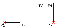
To construct a Line or a series of connected Lines:
- Click Draw > Line (or type Line).
- In the graphics area, specify:
- A point to start the line segment.
- A point to end the line segment.
- Another point to define the next segment or press Enter to finish the drawing.
 Each segment in a series of connected Lines is a separate entity. You can also use the Line command to append Lines to existing Lines or Arcs.
To undo a line segment:
- Press Ctrl + Z or type Undo.
- Press Ctrl + Z or type Undo.
- Specify the Undo option.
To close a Line drawing:
- Specify the Close option.
To append a line segment to an existing line or arc:
- Click Draw > Line (or type Line).
- Press Enter.
The appended continuation line attaches to the end of last Line or Arc that you drew.
- Click a point to define the appended line segment and press Enter.
Access
Command: Line
Menu: Draw > Line
Ribbon: Home > Draw > (Flyout) Line 
Tool Palettes: Draw > Line
Using InfiniteLines, CenterLines, and RichLines
You can use InfiniteLines and Rays to create a framework or grid to aid in drawing construction. You generally delete these when you complete the drawing.
You can use RichLines to create sets of parallel Lines with different colors and types. RichLines are useful for architectural floor plans and piping plans. You can create and manage styles for RichLines.
This chapter discusses:
Constructing Rays
A Ray is a Line that extends indefinitely in one direction from its origin. You can use Rays to establish frameworks or grids from which you construct a drawing.
To construct one or more Rays:
- Click Draw > Ray (or type Ray).
- In the graphics area, specify the:
- Ray’s start point.
- First Ray direction.
- Different through points to define other Rays through the same origin, or press Enter.
Draw Rays on separate Layers that you can turn off or freeze prior to printing. Alternatively, delete Rays when the drawing is complete.
Access
Command: Ray
Menu: Draw > Ray
Ribbon: Home > Draw > (Flyout) Ray
Constructing InfiniteLines
InfiniteLines are a set of one or more construction lines that extend indefinitely in both directions from an origin.
Use InfiniteLines to create frameworks or grids for use in drawing construction.
To construct one or more InfiniteLines:
- Click Draw > InfiniteLine (or type InfiniteLine).
- In the graphics area, specify the:
- Central position of the InfiniteLine.
- Through point to define the first InfiniteLine direction.
- Different through points to define other InfiniteLines through the same origin, or press Enter.
Draw InfiniteLines on separate Layers that you can turn off or freeze prior to printing. Alternatively, delete InfiniteLines when the drawing is complete.
To create horizontal InfiniteLines:
- Click Draw > InfiniteLine (or type InfiniteLine).
- Specify the Horizontal option.
- In the graphics area, specify:
- A point to define the line position.
- Other points to define parallel horizontal lines, or press Enter.
To create vertical InfiniteLines:
- Click Draw > InfiniteLine (or type InfiniteLine).
- Specify the Vertical option.
- In the graphics area, specify:
- A point to define the line position.
- Other points to define parallel vertical lines, or press Enter.
To create parallel InfiniteLines at an angle from the origin:
- Click Draw > InfiniteLine (or type InfiniteLine).
- Specify the Angle option.
- Type an angle value in the specified angle drawing units or specify the Reference option to specify a reference entity, and then enter the angle from the reference entity.
The InfiniteLine appears at the specified angle to the horizontal or to the specified entity.
- In the graphics area, specify:
- A point to define the line position.
- Other points to define parallel lines, or press Enter.
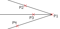
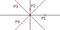
To create bisecting InfiniteLines from a vertex:
- Click Draw > InfiniteLine (or type InfiniteLine).
- Specify the Angle Bisect option.
- In the graphics area, specify:
- A point to define the vertex position.
- A point to define the first angle for the bisecting InfiniteLine.
- A point to define the second angle that determines the bisecting InfiniteLine through the vertex.
- Other points to define other bisecting InfiniteLines, or press Enter.
To create InfiniteLines that are offset from other linear entities:
- Click Draw > InfiniteLine (or type InfiniteLine).
- Specify the Offset option.
- Type an offset distance.
- In the graphics area:
- Select a linear source entity.
- Specify the location of the InfiniteLine.
- Repeat step 4 or press Enter.
Instead of performing steps 3 and 4, you can specify the Specify Position option, select a linear source entity, and click a point in the graphics area to define the offset distance.
Access
Command: InfiniteLine
Menu: Draw > InfiniteLine
Ribbon: Home > Draw > (Flyout) Infinite Line
Tool Palettes: Draw > InfiniteLine
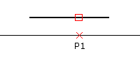
Constructing Centerlines
Use the Centerline command to construct Centerlines. You can set the extension for Centerlines to exceed the entities which define the contour.
The specific LineStyle for Centerlines is assigned automatically.
Centerlines are created between pairs of Lines, Arcs, and PolyLine segments.
Linear contours need not be parallel; the resulting line represents a bisecting line in this case. The two entities can be of different lengths.
Selected pairs of Arcs must be concentric.
You can create Centerlines continuously in one command. When you select pairs of PolyLine segments one after the other, the resulting centerline segments are joined to one entity, whereas each pair of lines or arcs creates separate Centerlines.
The Centerline represents an entity of its own.
To construct Centerlines:
- Do one of the following:
- On the ribbon, click Home > Annotations > Centerline.
- On the menu, click Draw > Centerline.
- Type Centerline.
- Specify the first entity.
- Specify the second entity of the same type (linear or curved).
The Centerline is created between the pair of entities.
- Repeat steps 2 and 3 for more pairs of Lines, Arcs, or PolyLine segments.
To undo the previously created Centerline, specify the Undo option.
- Press Enter.
To set Centerline extensions:
- Do one of the following:
- On the ribbon, click Home > Manage > Options.
- On the menu, click Tools > Options.
- Type Options.
- Click Drawing Settings.
- Expand Centerline Settings.
- In Centerline Extension, specify a value for the extension.
The default value is 0.25 (if you use an ANSI-based template drawing) or 2.5 (if you use an ISO-based template drawing) drawing units.
- Click OK
 .
.
Note: Use EntityGrips to modify the length of Centerlines which preserves their orientation.
Access
Command: Centerline
Ribbon: Home > Annotations > Centerline
Menu: Draw > Centerline
Constructing RichLines
You can use RichLines to draw 2 to 16 parallel linear entities.
You can create and manage styles for RichLines from Format > RichLine Styles.
To construct RichLine entities:
- Click Draw > RichLine (or type RichLine).
- In the graphics area, specify:
- A start point for the RichLine.
- Segment vertices to define the RichLine.
- Press Enter.
After specifying points, you can specify the Close option to close the RichLine entity.
To include justification options when creating RichLines:
When setting justification options, RichLines are drawn relative to the offset specification of the active RichLine Style.
- Click Draw > RichLine (or type RichLine).
- Specify the Justification option.
- Specify an option:
- Bottom. Draws the RichLine segment above the points you select, with the line element with the most negative offset at the specified vertices.
- Top. Draws the RichLine segment below the points you select, with the line element with the most positive offset at the specified vertices.
- Zero. Defines a centerline through the segment points you select.
- In the graphics area, specify:
- A start point for the RichLine.
- Segment vertices to define the RichLine.
- Press Enter.
To modify the RichLine scale:
- Click Draw > RichLine (or type RichLine).
- Specify the Scale option.
- Type a scale factor value.
The default scale factor is 1.0. For example, to halve the width of the RichLine, use a value of 0.5. This scale factor does not affect the overall LineScale factor.
- In the graphics area, specify:
- A start point for the RichLine.
- Segment vertices to define the RichLine.
- Press Enter.
To select a style when constructing a RichLine:
- Click Draw > RichLine (or type RichLine).
- Specify the Style option.
- Type a style name or specify the ? option to list RichLine Styles.
- In the graphics area, specify:
- A start point for the RichLine.
- Segment vertices to define the RichLine.
- Press Enter.
Access
Command: RichLine
Menu: Draw > RichLine
Ribbon: Home > Draw > (Flyout) RichLine
Managing RichLineStyles
RichLine entities consist of two or more parallel linear constructions created as one object. Before using RichLine entities, you can create custom RichLineStyles to specify the LineColor, LineStyle and other entity properties. The default RichLineStyle is named Standard.
To create RichLineStyles:
- Click Format > RichLine Styles (or type RichLineStyle).
- In the Options dialog box, the Drafting Styles page opens and RichLine expands.
- Click New.
- In the Create new RichLineStyle dialog box, type a new name.
- Click OK.
- The new style appears in Style.
To edit RichLineStyles:
- Click Format > RichLine Styles (or type RichLineStyle).
- In the Options dialog box, the Drafting Styles page opens and RichLine expands.
- In Style, select a RichLineStyle.
- Edit settings in:
-
Line properties: Specify the offset, LineColor, and style for each line element that comprises the RichLine entity.
- To add line elements to a RichLineStyle definition, click New.
- To delete line elements from a RichLineStyle definition, select a line element and click Delete.
- Display: Specify whether to display junctions at segment breaks and set the fill color.
- Cap ends: Specify the start and end caps of the RichLine entity.
-
Line properties: Specify the offset, LineColor, and style for each line element that comprises the RichLine entity.
- Click OK.
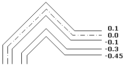
To modify line elements in RichLineStyle definitions:
- Click Format > RichLine Styles (or type RichLineStyle).
- In the Options dialog box, the Drafting Styles page opens and RichLine expands.
- In Style, select a RichLineStyle.
- Under Line properties, modify:
- Offset: The location of each line element in the RichLine entity is determined by its offset from the center of the entity. A line element with an offset of 0.0 is the center line.
- LineColor: Double-click the selected element under Color.
- Style: Double-click the selected element under Style. The list contains all LineStyles defined in the drawing. To add LineStyles, you must first create or import a LineStyle.
- Click OK.
-
To modify junction and cap ends in RichLineStyle definitions:
- Click Format > RichLine Styles (or type RichLineStyle).
- In the Options dialog box, the Drafting Styles page opens and RichLine expands.
- In Style, select a RichLineStyle.
- Under Display, select or clear Show junctions and specify the Color for junctions.
- Under Cap ends, specify cap settings for the Start and End caps:
- Angle: Sets the angle of the start and end caps relative to the direction of the first or last RichLine entity.
- External arc: Caps the outer ends with an arc.
- Internal arc: Joins the two line elements closest to the outer ones with an arc when there are four or more lines defining the RichLine entity.
- Line: Caps the RichLine entity with a line segment.
-
To set a RichLine Style as active:
- Click Format > RichLine Styles (or type RichLineStyle).
- In the Options dialog box, the Drafting Styles page opens and RichLine expands.
- In Style, select a RichLineStyle and click Activate.
- A
 displays beside the active RichLineStyle.
To save RichLineStyles:
- Click Format > RichLine Styles (or type RichLineStyle).
- In the Options dialog box, the Drafting Styles page opens and RichLine expands.
- In Style, select a RichLineStyle and click Export.
- In the Save RichLine Style dialog box, type a file name and click Save.
To import RichLineStyles:
- Click Format > RichLine Styles (or type RichLineStyle).
- In the Options dialog box, the Drafting Styles page opens and RichLine expands.
- Click Load.
- In the Load RichLine Definitions dialog box, click Browse to navigate to the .mln style file and click Open.
- Click OK.
To rename a RichLine Style:
- Click Format > RichLine Styles (or type RichLineStyle).
- In the Options dialog box, the Drafting Styles page opens and RichLine expands.
- In Style, select a RichLineStyle and click Rename.
- In the Rename RichLineStyle dialog box, change the name.
- Click OK.
To delete RichLineStyles:
- Click Format > RichLine Styles (or type RichLineStyle).
- In the Options dialog box, the Drafting Styles page opens and RichLine expands.
- In Style, select a RichLine Style and click Delete.
- Click Yes to confirm the deletion.
Access
Command: RichLineStyle
Menu: Format > RichLine Styles
Ribbon: Home > Annotations > RichLine Styles
Constructing PolyLines
A PolyLine is a drawing entity that consists of connected Lines or connected arc segments. You can create PolyLines with segments of different widths and fill settings. The default segment type for a PolyLine is a linear segment.
After you create a PolyLine, you can modify it using various methods.
- Use grip points to move, add, or delete vertices. Additionally, you can convert straight segments into arcs and viceversa.
- Use the EditPolyLine command to change the width of the whole PolyLine and tapering the entire PolyLine. Additionally, you can open a closed PolyLine or close an open PolyLine.
Note: The Properties palette groups several options for modifying PolyLines.
Using LineStyles with PolyLines
You can specify how PolyLine segments are drawn around the vertices of the PolyLine.
To construct PolyLines:
- Click Draw > PolyLine (or type PolyLine).
- In the graphics area, specify the start point for the first segment of the PolyLine.
- Specify options for the next segment:
-
Arc. Changes the segment type to an Arc.
The arc direction depends on the Clockwise option (see Specifying Units and Precision). Press Ctrl key when specifying an angle to draw the arc in the opposite direction.
- Angle. Defines an arc segment via its angle from the start point.
- Center. Defines an arc segment from its center.
- Direction. Defines an arc segment via the direction of a tangent to the start point.
- Halfwidth. Specifies the width symmetrically around the segment end point.
- Line. Changes the segment type to Line.
- Radius. Defines an arc segment from its radius.
- Through point. Specifies a point the next arc segment passes through.
- Undo. Undoes a previous segment.
- Width. Specifies the start and end width of the next PolyLine segment, creating a thick line or arc segment.
-
Arc. Changes the segment type to an Arc.
- Specify the segment end point.
- Do one:
- Specify each successive segment according to steps 3 and 4.
- After specifying at least two segments, specify the Close option to create a closed PolyLine, or press Enter.
To create a filled segment while creating a PolyLine:
- Click Draw > PolyLine (or type PolyLine).
- In the graphics area, specify the start point for the first segment of the PolyLine.
- Specify the Width option.
- Type the start width of the segment.
- Type the end width of the segment.
- Specify the segment end point.
The end width you specify persists for each subsequent PolyLine segment until you change it by specifying the Width option.
To specify an arc segment of a PolyLine from three points:
- Click Draw > PolyLine (or type PolyLine).
- In the graphics area, specify the start point for the first segment of the PolyLine.
- Specify the Arc option.
- Specify the Through point option.
- Specify the through point and arc end point.
To specify an arc segment of a PolyLine from a center point:
- Click Draw > PolyLine (or type PolyLine).
- In the graphics area, specify the start point for the first segment of the PolyLine.
- Specify the Arc option.
- Specify the Center option.
- Specify the arc center point.
- Specify the arc end point or specify an option:
- Angle. Specify an angle.
- Length. Specify a chord length.
To specify an arc segment of a PolyLine from a radius and three points:
- Click Draw > PolyLine (or type PolyLine).
- In the graphics area, specify the start point for the first segment of the PolyLine.
- Specify the Arc option.
- Specify the Radius option.
- Specify the arc radius and end point.
To specify an arc segment of a PolyLine from a radius, angle, chord direction, and two points:
- Click Draw > PolyLine (or type PolyLine).
- In the graphics area, specify the start point for the first segment of the PolyLine.
- Specify the Arc option.
- Specify the Radius option.
- Specify the arc radius.
- Specify the Angle option.
- Specify an included angle.
- In the graphics area, specify the chord direction and arc end point.
To specify an arc segment of a PolyLine from an angle from the start point along with an end point:
- Click Draw > PolyLine (or type PolyLine).
- In the graphics area, specify the start point for the first segment of the PolyLine.
- Specify the Arc option.
- Specify the Angle option.
- Type a positive or negative angle value.
- Specify the arc end point or specify an option:
- Center. Lets you specify the arc center point.
- Radius. Lets you specify the radius and chord direction.
To specify an arc segment of a PolyLine from a tangent direction from the start point along with an end point:
- Click Draw > PolyLine (or type PolyLine).
- In the graphics area, specify the start point for the first segment of the PolyLine.
- Specify the Arc option.
- Specify the Direction option.
- In the graphics area, specify the tangent direction for the start point of the arc and the arc end point.
Access
Command: PolyLine
Menu: Draw > PolyLine
Ribbon: Home > Draw > (Flyout) PolyLine
Tool Palettes: Draw > Polyline
Constructing 3D PolyLines
A 3D PolyLine is a linear drawing entity that consists of two or more connected line segments for which you specify 3D coordinates for each segment start and end point.
To construct 3D PolyLines:
- Click Draw > 3D PolyLine (or type PolyLine3D).
- In the graphics area, specify the start point for the first line segment of the 3D PolyLine or enter a start point in 3D coordinates.
- Specify the segment endpoint in 3D coordinates.
- Continue to specify additional vertices of the 3D PolyLine in 3D coordinates or specify an option:
- Undo. Undoes a previous segment.
- Close. Closes the 3D PolyLine and ends the command.
- Press Enter.
You can specify the Undo option to undo a previous segment.
Access
Command: PolyLine3D
Menu: Draw > 3D PolyLine
Ribbon: Home > Draw > (Flyout) 3D Polyline
Constructing Polygons
A polygon is a closed linear PolyLine entity consisting of 3 to 1024 equal length sides.
To construct polygons:
- Click Draw > Polygon (or type Polygon).
- Type the number of sides.
- Do one:
- In the graphics area, specify the center of the polygon.
- Specify an option:
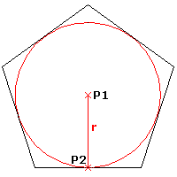
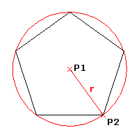
- Corner. Encloses the polygon within a circle that touches the polygon at its corners (inscribed).
- Side. Encloses a circle with the polygon that touches the circle at the corners (circumscribed).
- Specify a point in the graphics area to define the radius or type a value for the radius.
– or –
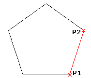
- Specify the Side length option to define an edge of the polygon.
- Specify the edge start point and side length.
Access
Command: Polygon
Menu: Draw > Polygon
Ribbon: Home > Draw > (Flyout) Polygon
Tool Palettes: Draw > Polygon
Constructing Rectangles
You can draw Rectangles with any size or orientation in the plane with square, filleted, or chamfered corners.
The Rectangle command provides the following options:
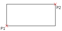
- Corner. Creates a rectangle by specifying two opposite corner points.
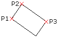
- 3 Point Corner. Creates a rectangle by specifying three points.
- 3 Point Center. Creates a rectangle by specifying the center of the rectangle, the mid-point of a side and a corner.
- Center. Creates a rectangle by specifying the center of the rectangle and a corner.
- Parallelogram. Creates a parallelogram by specifying three corner points.
Note: You cannot create parallelograms with chamfered or filleted corners.
To construct a rectangle from two opposite corner points:
- Click Draw > Rectangle (or type Rectangle).
- In the graphics area, specify the start point of the rectangle or specify an option:
- Chamfer. Lets you specify the chamfer distances for each corner.
- Elevation. Lets you specify the elevation of the rectangle in 3D.
- Fillet. Lets you specify the fillet radius for each corner.
- Thickness. Lets you specify the thickness of the rectangle walls in 3D.
- Line width. Lets you specify the 2D line width of the rectangle walls.
- In the graphics area, specify the opposite corner of the rectangle or specify an option:
- Area. Defines the rectangle by the area and the length or width. (Chamfering or filleting of corners is incorporated into rectangle area calculations.)
- Dimensions. Defines the rectangle by length and width.
- Rotation. Rotates the length side of the rectangle by a specified angle before specifying the opposite corner.
To specify rectangle options:
- Type Rectangle at the command prompt.
- Specify an option:
- Chamfer. Lets you specify the chamfer distances for each corner.
- Elevation. Lets you specify the elevation of the rectangle in 3D.
- Fillet. Lets you specify the fillet radius for each corner.
- Thickness. Lets you specify the thickness of the rectangle walls in 3D.
- Line width. Lets you specify the 2D line width of the rectangle walls.
Note: The specified options remain active until you will specify other options.
- Press Enter.
- Repeat step 2 and 3 as necessary to set the options.
- Press Esc to exit the command or specify an option to draw a rectangle.
To construct a rectangle from three points:
- Click Draw > Rectangle > 3 Point Corner (or type Rectangle then specify the 3Corner option).
- In the graphics area, specify:
- First corner point.
- Second corner point to define the first side of the rectangle.
- Third point.
To construct a rectangle from the center, mid-point, and a corner point:
- Click Draw > Rectangle > 3 Point Center (or type Rectangle then specify the 3Point center option).
- In the graphics area, specify:
- Center point of the rectangle.
- The mid-point of a side.
- A corner point.
To construct a rectangle from the center point:
- Click Draw > Rectangle > Center (or type Rectangle then specify the Center option).
- In the graphics area, specify:
- Center point of the rectangle.
- A corner of the rectangle.

To construct a parallelogram:
Note: You cannot create parallelograms with chamfered or filleted corners.
- Click Draw > Rectangle > Parallelogram (or type Rectangle then specify the Parallelogram option).
- In the graphics area, specify:
- First corner of the parallelogram.
- Second point to define the first side of the parallelogram.
- Specify the third point of the parallelogram.
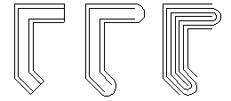
Regular rectangle:
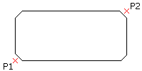
Rectangle with Chamfer option:
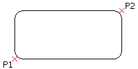
Rectangle with Fillet option:
Access
Command: Rectangle
Menu: Draw > Rectangle
Tool Palettes: Draw > Rectangle
Ribbon: Home > Draw > Rectangle > Corner
Home > Draw > Rectangle > Center
Home > Draw > Rectangle > 3 Point Corner
Home > Draw > Rectangle > 3 Point Center
Home > Draw > Rectangle > Parallelogram
Constructing Arcs
You can construct arcs of any length or radius. You can also append Arcs to other Line, PolyLine, or Arc entities. By default, Arcs are drawn from the start point in the positive direction. The default direction depends on the Clockwise option (see Specifying Units and Precision).
To construct Arcs from three points:
- Click Draw > Arc > 3 Points (or type Arc).
- In the graphics area, specify the start, through, and endpoints.
To construct Arcs from center points:
- Click Draw > Arc and specify a center-based option:
- Start, Center, Angle: Lets you select the start and center point in the graphics area. Then you specify the value of the total angle from its chord.
- Start, Center, End: Lets you select the start, center, and endpoint in the graphics area.
- Start, Center, Length: Lets you select the start and center point in the graphics area. Then you enter the value of the arc chord length.
Press Ctrl key when specifying an angle to draw the arc in the opposite direction. - Specify the required points in the graphics area or specify coordinate values.
To construct an Arc from start and endpoint options:
- Click Draw > Arc and specify a start and endpoint-based option:
- Start, End, Angle to select the start point and endpoint in the graphics area, and specify the positive or negative value of the angle from the chord tangent to the start point.
- Start, End, Direction to select the start point, endpoint, and tangent direction from the start point in the graphics area.
- Start, End, Radius to select the start point and endpoint in the graphics area, and specify the value of the arc angle tangent from its chord.
Press Ctrl key when specifying an angle to draw the arc in the opposite direction. - Specify the required points in the graphics area or specify coordinate values.
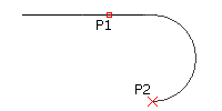
To append an Arc tangentially to a Line, PolyLine, or Arc:
- Click Draw > Arc (or type Arc).
- Specify the Append option.
- In the graphics area, select a Line, PolyLine, or Arc entity.
– or –
Press Enter if you want to append the Arc to the most recently drawn Line, PolyLine, or Arc.
- Specify the endpoint of the Arc.
To continue an Arc from the end of the most recently drawn Line, PolyLine, or Arc:
- Click Draw > Arc > Continue (or type Arc, then press Enter).
- In the graphics area, specify a through point (or select an option).
- Specify the endpoint of the Arc.
Access
Command: Arc
Menu: Draw > Arc
Tool Palettes: Draw > Arc
Ribbon: Home > Draw > Arc
Constructing Circles
You can use one of several methods to create Circles.
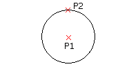
To construct a Circle from its center point and radius:
- Click Draw > Circle > Center, Radius (or type Circle).
- In the graphics area, specify the:
- Center point of the Circle.
- Circle radius.
To construct a Circle from its center point and diameter:
- On the menu, click Draw > Circle > Center, Diameter.
- In the graphics area, specify the:
- Center point of the Circle.
- Circle diameter.
To construct a Circle from three points:
- Click Draw > Circle > 3 Points (or type Circle then specify the 3Point option).
- In the graphics area, specify three points that define points on the Circle.
To construct a Circle from two points along the diameter:
- Click Draw > Circle > 2 Points (or type Circle then specify the 2Point option).
- In the graphics area, specify two points that define the Circle diameter.
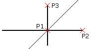
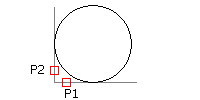
To construct a Circle from two tangent entities and the radius:
- Click Draw > Circle > Tangent, Tangent, Radius (or type Circle then specify the Ttr option).
- In the graphics area:
- Select a point on each of two linear entities that define lines tangent to the Circle.
- Specify two points to define the radius, or type the radius value.
To construct a Circle that is tangent to three lines:
- Click Draw > Circle > Tangent, Tangent, Tangent (or type Circle then specify the TTT option).
- In the graphics area, specify a point on three linear entities that define lines tangent to the Circle.
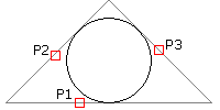
This option is useful when inscribing the Circle within a regular polygon.
Access
Command: Circle
Menu: Draw > Circle
Tool Palettes: Draw > Circle
Ribbon: Home > Draw > Circle > Circle
Constructing Rings
You can construct a Ring of any thickness or size by specifying the diameters of two concentric Circles. The area between the Circles is filled. A filled Circle has an inner diameter of zero.
To construct Rings and filled Circles:
- Click Draw > Ring (or type Ring).
- In the graphics area, specify the inner diameter or enter a value. For a filled circle, enter 0.
- Specify the outer diameter, or enter a value.
- In the graphics area, specify the center point of the Ring.
- (Optional) Continue to specify the centers of identical Rings.
- Press Enter to end the command.
Access
Command: Ring
Menu: Draw > Ring
Ribbon: Home > Draw > (Flyout) Ring
Constructing Ellipses and Elliptical Arcs
An Ellipse has a center like a Circle, but has a longer radius along its major axis and a shorter radius along its minor axis. You can construct Ellipses or elliptical Arcs of any size.
To construct Ellipses from a center point and the radii of perpendicular axes:
- Click Draw > Ellipse > Center (or type Ellipse, then specify the Center option).
- In the graphics area, specify:
- Center of the ellipse’s axes.
- Axis end point.
- Radius of the perpendicular axis.
– or –
Specify the Rotation option to create the Ellipse via the angle that is defined by the ratio of the major to minor axis. You can specify an angle between 0 and 89.9°. The larger the angle, the flatter the Ellipse.
To construct Ellipses from an axis defined by its end points and the radius of the perpendicular axis:
- Click Draw > Ellipse > Axis, End (or type Ellipse).
- In the graphics area, specify:
- Axis start point.
- Axis end point.
- Radius of the perpendicular axis.
To construct elliptical Arcs:
- Click Draw > Ellipse > Arc (or type Ellipse, then specify the Elliptical arc option).
- In the graphics area, specify:
- Axis start point.
- Axis end point.
- Radius of the perpendicular axis.
- End point of the Arc, or type the angle between a Ray from the Ellipse center to its intersection with the Ellipse.
- Angle defining the Ray from the Ellipse center axis intersecting the Ellipse at the other end point of the Arc, or specify an option:
- Parametric vectors: Specifies the Arc by the factor that defines its portion of the entire Ellipse area.
- Total angle: Specifies the other arc end point on the Ellipse from a Ray defined by an included angle defined by the Ellipse axes.
Access
Command: Ellipse
Menu: Draw > Ellipse
Ribbon: Home > Draw > (Flyout) Ellipse
Tool Palettes: Draw > Ellipse
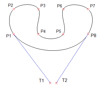
Constructing Splines
Use the Spline command to create open or closed Splines. Splines are smooth curves that are fit to a set of points.
The Splines you create are called non-uniform rational B-splines (NURBS).
Splines are defined either with fit points, or with control vertices. Accordingly, you can apply two methods with the command:
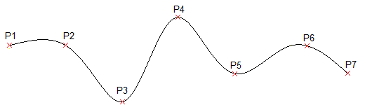
- Fit points method. Fit points coincide with the Spline. You can fit the Spline to the specified points within a specified tolerance value.
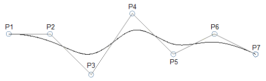
- Control vertices method. Control vertices (CV) define a control frame. Control frames provide an efficient method for shaping the Splines.
Depending on the selected method, the command prompts differ.
The following procedures describe specific command sequences:
- Spline creation without applying specific options
- Spline creation using fit points
- Spline creation using control vertices
Spline creation without applying specific options
The following command sequence is valid regardless of the method you selected.
To construct Splines:
- Do one of the following:
- On the menu, click Draw > Spline.
- On the ribbon, click Home > Draw > Spline.
- Type Spline at the command prompt.
- In the graphics area, specify the start point of the Spline.
- Specify successive points to continue the Spline.
Use the Undo option to cancel the previous point specification.
- Do one of the following:
- Specify Close to close the Spline curve. This ends the command.
When applying the Fit Points method, specify a closing tangency of the Spline.
- When applying the Fit Points method, press Enter to specify the Start Tangency of the Spline, then specify the End Tangency to complete the Spline.
- When applying the Control vertices method, press Enter to exit the command. The Spline curve remains open.
- Specify Close to close the Spline curve. This ends the command.
Spline creation using fit points
Running the Spline command using the Fit Points method creates degree 3 (cubic) B-splines. You specify control points through which the Spline passes.
To construct Splines using fit points:
- Run the Spline command.
- Specify the Method option, then specify Fit.
The Fit Points method is the default method unless you change it.
- Do one of the following:
- In the graphics area, specify the start fit point of the Spline.
- Specify options:
-
Knots. Specifies the knot computational method.
This option is available only if the Fit method is active.
- Chord. Sets the knots connecting each component curve so that they are proportional to the distances between each associated pair of fit points. This type of knot parameterization is known as chord length method. Chord is the default option.
- Square root. Sets the knots connecting each component curve so that they are proportional to the square root of the distance between each associated pair of fit points. This type of knot parameterization is known as centripetal method.
- Uniform. Sets the distances of the knots of each component curve so that they are equal, regardless of the distance of the fit points. This type of knot parameterization is known as equidistant method method.
Once you have set the option, specify the starting point for the Spline.
- Entity. Converts 2D or 3D quadratic or cubic spline-fit Polylines to equivalent Splines and ends the command.
-
Knots. Specifies the knot computational method.
- Specify the next fit point.
- Do one of the following:
- Specify successive fit points to continue the Spline.
- Specify options:
-
Fit tolerance. Specifies how closely the Spline matches its fit points.
Setting the fit tolerance to zero forces the Spline to pass through the fit points (default). With a value greater than zero, the Spline passes further away from fit points.
The fit tolerance value applies to all fit points until you change it.
- Undo. Cancels the previous point specification.
- Close. Closes the Spline curve and ends the command.
-
Fit tolerance. Specifies how closely the Spline matches its fit points.
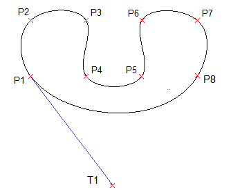
- Press Enter to specify the Start Tangency of the Spline, then specify the End Tangency to complete the Spline.
These point specifications determine the tangent conditions on the start point and on the endpoint of the Spline. Lines that are tangent to the Spline display dynamically from the start point and the endpoint of the Spline.
Spline creation using control vertices
Running the Spline command using the Control Vertices method creates Splines of degree 1 (linear), degree 2 (quadratic), degree 3 (cubic), and so on up to degree 5. You specify control points, not points through which the Spline passes.
To construct Splines using control vertices:
- Run the Spline command.
- Specify the Method option, then specify Control vertices (CV).
- Do one of the following:
- Specify the start control point of the Spline.
- Specify options:
-
Degree. Specifies the degree for subsequent Spline constructions.
The default value is 3 for degree 3 (cubic) Splines. Specify a value between 1 and 5.
Once you have set the option, specify the starting point for the Spline.
- Entity. Converts 2D or 3D quadratic or cubic spline-fit Polylines to equivalent Splines and ends the command.
Once you have set options, specify the starting point for the Spline.
-
Degree. Specifies the degree for subsequent Spline constructions.
- Specify the next control vertex.
- Do one of the following:
- In the graphics area, specify successive points to continue the Spline.
- Specify options as needed:
- Undo. Cancels the previous point specification.
- Close. Closes the Spline curve and ends the command.
Access
Command: Spline
Menu: Draw > Spline
Tool Palettes: Draw > Spline Fit, Spline CV
Ribbon: Home > Draw > (Flyout) Spline Fit
Constructing 2D Spirals and 3D Helixes
Use the Helix command to construct 2D spirals and 3D helixes.
Spirals and helixes are entities of their own. You can use 2D spirals and 3D helixes as paths to create threads, springs, and spiral stairs. For example, you can sweep a 2D entity along a helix and create threaded bolts.
You can create the following entities:
- 2D spirals
- Conical 3D helixes
- Cylindrical 3D helixes
You create 3D helixes around an axis that defines their location and position. You define the axis by specifying two points (the base center point and the top center point) or by specifying the base center point and the height. The helix axis can be vertical or sloped.
After you create a helix, you can modify it using EntityGrips or the Properties palette. See Modifying 2D Spirals and 3D Helixes.
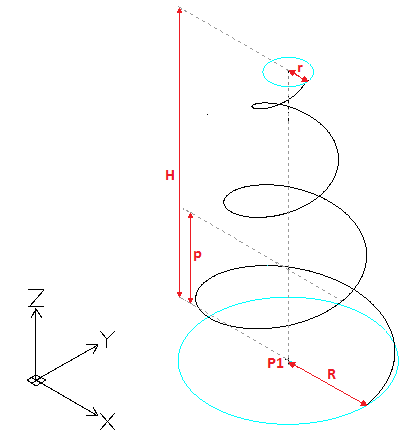
Helix Parameters
To sketch a helix, specify these parameters:
- Axis position. Defines the helix position. Specify the axis’ base center point and end point.
- Base radius or Base diameter. Defines the helix base (the circle created by the helix when seen from the top) by specifying the base radius or diameter.
-
Top radius or Top diameter. Defines the helix top circle by the top radius or diameter. The base and top radii or diameter must not be zero.
- To create a cylindrical helix specify the same value for both the base radius (or diameter) and top radius (or diameter).
- To create a conical helix specify different values for the base radius (or diameter) and top radius (or diameter).
-
Height. Defines the helix height and the direction in the Z axis.
- Positive value. Creates the helix (spiral) towards the positive direction of the Z axis.
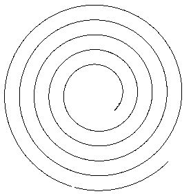
- 0 (zero). Creates a 2D spiral.
- Negative value. Creates the helix (spiral) towards the negative direction of the Z axis.
- Revolutions. Specifies the number of revolutions for the helix. After specifying the height, the command draws the specified number of revolutions evenly distributed.
- Pitch. Specifies the distance between two revolutions, measured along the helix axis. If you specify a pitch, the number of revolutions is automatically calculated. The higher the pitch, the lower the number of revolutions.
- Direction. Defines the direction in which the helix is twisted: clockwise (CW) or counterclockwise (CCW).
 |
Number of revolutions = 3 |
Creation Methods
You can create 3D helixes by specifying the:
- height (other parameters have default values)
- number of revolutions and height. The number of revolutions are created within the specified height, at equal distances.
- pitch and height. The number of revolutions is automatically calculated.
- pitch and number of revolutions for the spiral. The height is automatically calculated.
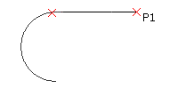
To construct 2D spirals:
- Do one of the following:
- On the ribbon, click Home > Draw > Helix.
- On the menu, click Draw > Helix.
- Type Helix.
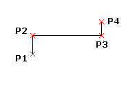
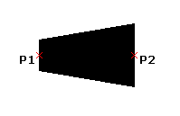
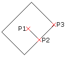
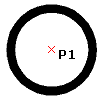
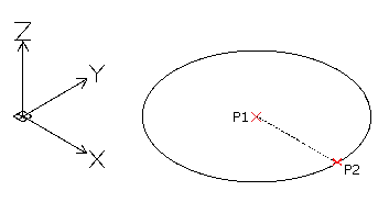
- In the graphics area, specify the base center point (P1) to define the 2D spiral position.
- Do one of the following:
- Specify a point (P2) to define the base radius.
This point defines the start point.

– or –
Do the following:
- Type a value to define the base radius.
- Specify the start angle.
- Specify the Diameter option and do the following:
- Specify the base diameter.
- Specify the 2D spiral start point or type the start angle value.
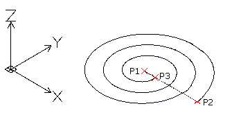
- Specify a point (P2) to define the base radius.
- Specify the top radius (P3).
– or –
Specify the Diameter option and specify the top diameter.
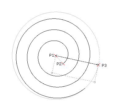
- Specify the Direction and Revolutions options as needed. See Helix Parameters.
For example, specify 5 for the number of revolutions.
- Specify 0 for the height of the helix.
After creating the spiral, you can modify it using EntityGrips or the Properties palette. See Modifying 2D Spirals and 3D Helixes.
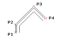
To construct 3D helixes:
- Do one of the following:
- On the ribbon, click Home > Draw > Helix.
- On the menu, click Draw > Helix.
- Type Helix.
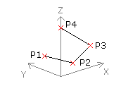
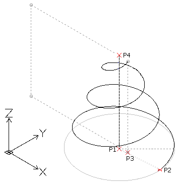
- In the graphics area, specify the base center point (P1) to define the helix position.
- Do one of the following:
- Specify a point (P2) to define the base radius.
This point defines the helix start point.
– or –
- Do the following:
- Type a value to define the base radius.
- Specify the start angle.
– or –
Specify the Diameter option and do the following:
- Specify the base diameter.
- Specify the helix start point or type the start angle value.
- Specify a point (P2) to define the base radius.
- Specify the top radius (P3).
– or –
Specify the Diameter option and specify the top diameter.
Note: The default value of the top radius (or diameter) is always the value of the base radius (or diameter). Use the default value of the top radius (or diameter) to create a cylindrical 3D helix.
- Specify the height of the helix (P4).
– or –
Use the following options as needed. See Helix Parameters.
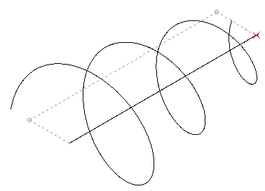
-
Axis endpoint. Specifies the end point of the helix axis. The end point defines the length of the axis and orientation of the helix.
Tip: You can specify the axis endpoint anywhere in the 3D environment. Use this option to sketch the helix at an angle.
- Direction. Specifies the direction in which the helix is twisted.
- Pitch. Specifies the distance between two revolutions of the helix.
- Revolutions. Specifies the number of revolutions of the helix.
-
Axis endpoint. Specifies the end point of the helix axis. The end point defines the length of the axis and orientation of the helix.
- Press Enter.
After creating the helix, you can modify it using EntityGrips or the Properties palette. See Modifying 2D Spirals and 3D Helixes.
Modifying 2D Spirals and 3D Helixes
Use EntityGrips or the Properties palette to modify 2D spirals and 3D helixes.
Use EntityGrips to modify the following properties:
- Axis position
- Start point
- Base radius
- Top radius
- Height
- Direction in Z axis
Use the Properties palette to modify other properties, such as:
- Twist direction
- Number of revolutions
- Pitch
Additionally, you can select a Constraint, the dimension that remains constant when you create or modify helixes:
- Pitch. The pitch value is constant. As the height changes, the number of revolutions is calculated.
- Revolutions. The number of revolutions is constant. As the height changes, the distance between revolutions is calculated.
- Height. As the height changes with the EntityGrip, the number of revolutions is unchanged and the distance between revolutions is calculated.
Access
Command: Helix
Menu: Draw > Helix
Ribbon: Home > Draw > (Flyout) Helix
Working with Points
Points are often used as temporary drawing aids, similar to InfiniteLines and Rays.
You can use the Single Point or Multiple Points commands to place points in a drawing.
MarkDivisions and MarkLengths are commands you can use when creating points. These commands place points, or symbols, along other drawing entities. You can use them to set out distances along a Line or more complex entities, which is useful in construction processes.
Set a point format before placing points in a drawing because they can be difficult to see after you place them.
This section discusses:
- Inserting Points
- Marking Entities with Points or Blocks by Segments
- Marking Entities with Points or Blocks by Lengths
- Setting the Point Format
Setting the Point Format
You can set the display format and size of points. Although mathematically points have no size, you can specify the display size.
When you use the Point command the appearance of the points depends on the settings for the point format.
To set the point format:
- Click Format > Point Style (or type PointFormat).
In the Options dialog box, the Drawings Settings page opens and Points expands.
- In Type, select the display format.
- For Size, type a value.
- Select a size option:
- Absolute units. Point size is set in a value of drawing units.
- % Relative to display. Point size is a percentage of the visible drawing plane.
- Click OK.
All points in the drawing adopt the new format.
Access
Command: PointFormat
Menu: Format > Point Style
Ribbon: Home > Annotations > Point Style
Inserting Points
The Point command draws a point, usually used as a reference in drawings.
Points can serve as nodes to which you can snap entities, especially in 3D construction processes. Later, when the points are no longer necessary, you delete them.
An advantage to using points during construction is that you can use EntitySnaps to snap points. You can also use ETracking or the snap option From instead of inserting point entities into the drawing.
Points can be displayed in different styles and sizes.
You can use points as symbols in drawings, but only one point style can be active in a drawing.
To insert one point:
- Click Draw > Point > Single Point (or type Point).
- In the graphics area, specify the point location, or type the coordinates.
Use the coordinate filter and inferencing for precise placement.
- Click Draw > Point > Multiple Points (or type Point, and specify the Multiple option).
- In the graphics area, specify the point location, or type the coordinates.
- Repeat step 2 until you finish inserting points, and press Esc.
If you use points for temporary reference, before you print or plot a drawing you can set the point style to no dot instead of deleting them. Alternatively, insert construction points on a separate Layer which you can turn off or freeze prior to printing or plotting, or which you can delete when the construction is finished.
Access
Command: Point
Menu: Draw > Point
Ribbon: Home > Draw > (Flyout) Single Point
Tool Palettes: Draw > Point
Marking Entities with Points or Blocks by Segments
The MarkDivisions command places evenly spaced points or Blocks along the length or perimeter of an entity.
The command lets you “separate” lines, PolyLines, Circles, and Arcs into segments of equal length by inserting construction points or Blocks. The entity is not cut into different pieces but remains one entity.
The size of the segments is determined by the length to divide and the number of construction points to insert. In contrast to the MarkLengths command, there is no remainder.
To mark entities with points by segments:
- Click Draw > Point > By Segments (or type MarkDivisions).
- In the graphics area, select the entity you want to divide by segments.
- Type the number of segments you want. Use a whole integer between 2 and 32767.
To mark entities with Blocks by segments:
- Click Draw > Point > By Segments (or type MarkDivisions).
- In the graphics area, select the entity you want to divide by segments.
- Specify the Block option.
- Type the Block name.
- Type Yes or No to align the Block with the entity to mark.
- Type the number of divisions you want. Use a whole integer between 2 and 32767.
Access
Command: MarkDivisions
Menu: Draw > Point > By Segments
Ribbon: Home > Draw > (Flyout) Mark Divisions
Marking Entities with Points or Blocks by Lengths
The MarkLengths command places points or Blocks at measured intervals on an entity.
The command lets you “separate” Lines, PolyLines, Circles, Arcs, or other entities into segments of a certain length by inserting construction points or Blocks. The entity is not cut into different pieces but remains one entity.
In contrast to the MarkDivisions command, entities that are not an exact multiple of the length of the segment will have a remainder.
To mark an entity with points by lengths:
- Click Draw > Point > By Lengths (or type MarkLengths).
- In the graphics area, select the entity you want to mark.
- Type a value to set the length of the segments or specify the start and end points of the segment in the graphics area.
To mark an entity with Blocks by lengths:
- Click Draw > Point > By Lengths (or type MarkLengths).
- In the graphics area, select the entity you want to mark.
- Specify the Block option.
- Type the Block name.
- Type Yes or No to align the Block with the entity.
- Type a value to set the length of the segments or specify the start and end points of the segment in the graphics area.
Access
Command: MarkLengths
Menu: Draw > Point > By Lengths
Ribbon: Home > Draw > (Flyout) Mark Lengths
Creating Area Boundaries
You can create an area boundary from existing entities that form a 2D enclosed area.
Use the AreaBoundary command for:
- Area calculations
- Hatches
- Extracting outlines based on temporary constructions
The entities can be a combination of Lines, Arcs, Circles, PolyLines, Ellipses, elliptical Arcs, and Splines. The entities can be in any arrangement as long as the boundary makes an enclosed area without overlap.
To create AreaBoundaries:
- Click Draw > Bound Area (or type AreaBoundary).
- In the dialog box, set options:
- Find nested boundaries. Controls whether the command detects internal closed areas that are completely within the boundary area.
- Under Performance, in Analyze entities, select the set of drawing entities that are analyzed when defining a boundary from a specified point:
- As Displayed. Establishes the boundary set from everything currently visible on the drawing screen.
-
Entities specified. Displays the number of specified entities after you click Specify entities
 to select drawing entities on screen to form the boundary set.
- Under Type, select whether to define the boundary by PolyLine or Region.
- Click OK.
- Click any point inside the closed area to designate as a boundary entity. To create other boundary entities, click additional internal points.
- Press Enter.
Access
Command: AreaBoundary
Menu: Draw > Bound Area
Ribbon: Home > Draw > (Flyout) Area Boundary
Creating Regions
The Region command transforms an entity that forms a closed shape into a 2D Region entity. You can use the command to combine all entities of any closed loop – such as closed PolyLines (including polygons and Rings), Circles, Ellipses, and closed Splines – into one entity.
After creating a Region, there is little visual difference on screen except when the original entity had a width, thickness, or LineWeight. This information is lost when you create a region from such entities.
A Region is a planar solid entity. If you set ShadeView mode to Flat, you will see that the Region is a surface, not simply a boundary contour.
If the source entities of the Region are hatched, the Hatch loses associativity to the boundary. You must apply the Hatch to the Region entity again.
You can also create Regions with the AreaBoundary command by setting the resulting entity type for boundaries to Region.
To create Regions:
- Click Draw > Region (or type Region).
- In the graphics area, select closed drawing entities to transform into a Region.
- Press Enter.
Access
Command: Region
Menu: Draw > Region
Ribbon: Home > Draw > Region
Tool Palettes: Draw > Region
Creating a Mask
You can create a Mask, a figure that overlays existing geometry with the current background color. The existing geometry is not erased.
The Mask command allows you to draw a polygonal shape or select an existing polygon to mask underlying entities. After you place the polygon over a section of the drawing, you can add entities on top of the polygon.
Annotate a masked area by placing opaque Text near it, or by highlighting areas of a drawing that need to be re-detailed, for example.
You can turn off Mask frames to seamlessly blend with existing drawing entities. This is helpful before you print a drawing.
To control the visibility of different scenarios with Masks, use Layers.
To create a Mask out of points:
- Click Draw > Mask (or type Mask).
- In the graphics area, specify points in a sequence that define the contour of the area to mask.
- Press Enter.
To create a Mask from a PolyLine:
- Click Draw > Mask (or type Mask).
- Specify the PolyLine option.
- In the graphics area, select a PolyLine. The PolyLine must be closed and consist of Line segments with zero width.
- Specify the Yes option to keep the polyline.
To show or hide Mask frames:
- Click Draw > Mask (or type Mask).
- Specify the Frames option.
- Specify the Yes option to show Mask frames. Specify the No option to hide them.
Access
Command: Mask
Menu: Draw > Mask
Ribbon: Annotate > Revision > Mask
Creating Revision Clouds
Use the Cloud command to create revision clouds. Revision clouds are used in drawings to indicate that certain areas require or contain revisions. You can create rectangular, elliptical and freehand Clouds to accentuate drawing areas. Additionally, you can convert drawing entities, such as rectangles, polylines, circles, ellipses, and splines into revision clouds.
Additional settings let you adjust the sequential arcs of clouds.
Optionally, you can create the revision cloud as a simple set of connected arcs or as calligraphy styled arcs.
To construct rectangular Clouds:
- Click Draw > Cloud (or type Cloud).
- Specify the Rectangle option.
- In the graphics area, specify the start corner of the rectangular shape.
- Specify the opposite corner of the rectangular shape.
To construct elliptical Clouds:
- Click Draw > Cloud (or type Cloud).
- Specify the Elliptical option.
- In the graphics area, specify the start point of the first axis of the elliptical shape.
- Specify the end point of the first axis of the elliptical shape.
- Specify the end point of the other axis.
To construct freehand Clouds:
- Click Draw > Cloud (or type Cloud).
- Specify the Freehand option.
- In the graphics area, specify the start point of the freehand shape.
- Specify the next point of the freehand shape.
– or –
Press Enter to go back to restart with specifying a new start point.
- Continue to specify additional vertices of the freehand shape or specify an option:
- Undo. Undoes a previous segment.
- Close. Closes the contour and ends the command.
- Press Enter.
Note: Open contours close automatically.
To convert an entity to a revision cloud:
- Click Draw > Cloud (or type Cloud).
- Specify the Entity option.
- In the graphics area, specify the entity to convert to a revision cloud.
- Do one:
- Press Enter to keep the default direction of the arcs.
- Specify Yes to reverse the direction of the arcs.
- Press Enter.
To create a revision cloud with calligraphy pen style:
- Click Draw > Cloud (or type Cloud).
- Specify the Settings option.
- In the dialog box, select Calligraphy style.
- Click OK and continue with the command.
To set the radius for Cloud creation:
- Click Draw > Cloud (or type Cloud).
- Specify the Radius option.
- Specify the radius for the Cloud’s sequential arc segments.
- Press Enter.
To set preferences for Cloud creation:
- Click Draw > Cloud (or type Cloud).
- Specify the Settings option.
- In the dialog box, set preferences:
-
Shape options: Sets the shape type: Rectangular
 , Elliptical
  , Freehand
  , or Entity
  .
. - Calligraphy style: Draws revision clouds as if drawn with a calligraphy pen.
- Radius: Sets the radius for sequential arc segments of Clouds.
- Layer: Sets the Layer on which you place Clouds.
- LineColor: Sets the Cloud LineColor.
- LineStyle: Sets the Cloud LineStyle.
- LineWeight: Sets the Cloud LineWeight.
-
Shape options: Sets the shape type: Rectangular
- Click OK.
Use the Properties palette to modify the Cloud sequential arc segment radius, Layer, LineColor, LineStyle, LineWeight, position, and scale.
Access
Command: Cloud
Menu: Draw > Cloud
Ribbon: Annotate > Revision > Cloud
Sketching
Use the Sketch command to draw freehand. A sketch consists of many straight Line segments.
To sketch:
- Click Draw > Sketch (or type Sketch).
- Type the record increment (length of the sketch segments).
- Specify an option:
- Erase: Deletes parts of temporary sketch Lines drawn previously.
- Connect: Lowers the pen to continue sketching from the end point of the last sketched Line or last Erase.
- Pen: Lowers or lifts the sketching pen.
- Quit: Discards all temporary sketch segments since the start of the command, or since the last use of the Record option. The command terminates.
- Record: Records temporary segments as permanent.
- Exit: Records the temporary segments and terminates the command.
- In the graphics area, click to start sketching (lower the pen).
- Click again to interrupt sketching (lift the pen). Continue clicking to lower and lift the pen.
- Press Enter to make the temporary sketch permanent and end the command.
Access
Command: Sketch
Menu: Draw > Sketch
Loading and Inserting Shapes
You can insert Shapes that are defined in compiled shape files (.shx files) into drawings. To use Shapes you previously must load them.
This section discusses:
Loading Shapes
Use the LoadShape command to use shapes defined in compiled shape files (.shx files) with the InsertShape command.
To load shapes:
- Click Draw > Shape > Load (or type LoadShape).
- In the dialog box, navigate to the .shx file containing shapes, and click Open.
You must load the shape file before a shape defined in that file can be used in a drawing.
Access
Command: LoadShape
Menu: Draw > Shape > Load
Inserting Shapes
The InsertShape command inserts a shape from a compiled shape file (.shx file).
To insert shapes:
- Make sure the file containing the shape to insert is loaded in the drawing.
You can load the shape with the LoadShape command.
- Click Draw > Shape > Define (or type InsertShape).
- Type the shape name, or specify the ? option to list the shapes.
- Specify the insertion point.
- Specify the height of the shape.
- Specify the rotation angle of the shape.
Access
Command: InsertShape
Menu: Draw > Shape > Define