
Introduction
This chapter describes the commands for creating, opening, and saving drawing files.
You can open drawing files created in other CAD programs or save files to open them in other applications.
These commands support the following file types:
- DWG (Drawing files)
- DWS (Drawing Standard files)
- DWT (Drawing Template files)
- DXF (Drawing Exchange Format)
- DWF (Design Web Format)
- SHP (Shape file)
You can also:
- Use drawing tabs at the top of the drawing window to control multiple open drawings.
- Export and import drawings.
- Use drawing utilities to back up, check, recover, and clean drawing files.
To learn how to create and manage layouts, see Creating Sheets and Printing Drawings.
Using Drawing Tabs
Use the DrawingTabs command to show drawing tabs at the top of the drawing window area. The HideDrawingTabs command hides the drawing tabs.
Drawing tabs provide an easy way to control multiple open drawings.
The tab of the active drawing is white; all other drawing tabs are gray. When you hover over a tab, a tooltip displays the complete path and full name of the drawing file (saved drawings only).
Shortcut menus for the tabs bar provide file commands and options to control the tabs.
Preview panels with thumbnails for each workspace (model or layout sheet) of the open drawings appear as you hover over the tabs. Previews update when you save the drawing or switch between workspaces. If not all thumbnails fit to a preview panel, arrows at both ends of the panel scroll thumbnails to the right or left.
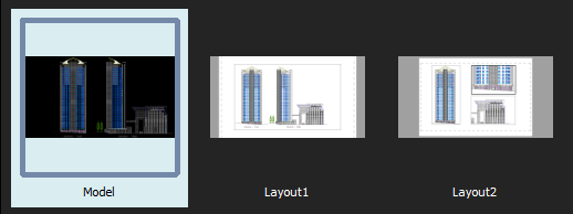
Preview panel
You can reorder the drawing tabs by dragging them.
If more drawings are open than the tabs bar can display:
- Click List All Drawings
 to display a list of all open drawings and select one as needed.
 - Click
 or
or  to move the tabs in the desired direction on the tabs bar.
Asterisks (*) at the end of file names on drawing tabs indicate unsaved drawings.
You can set preferences to show or hide the drawing tabs bar and to select the preview panel display mode.
To add a new drawing tab:
- Click
 next to the last drawing tab.
If no drawing is open, the drawing tabs bar displays the plus icon at the left.
The new drawing uses the default template drawing (similar to the SmartNew command).
To close a drawing tab:
- Do one of the following:
- Click
 on the drawing tab to close.
 - Hover over the drawing tab to close and middle-click.
If the drawing has changed since it was last saved, a prompt asks whether to save the changes.
- Click
To switch to another drawing:
- Click the tab of the drawing to display.
– or –
- Press Ctrl+Tab to cycle through open drawing tabs.
To switch to a specific workspace of a drawing:
- Hover over specific drawing tab.
Preview panels appear below the tab displaying the model and all layout sheets with the active workspace highlighted.
- Select a thumbnail (model or layout sheet) from the preview panel.
The selected workspace displays.
To control drawing tabs with the shortcut menu:
- Right-click a drawing tab or the icon and select an option from the shortcut menu:
- New. Starts a new drawing with a template drawing.
- Open. Opens an existing drawing.
- Open from Cloud. Displays the Cloud Storage palette and lets you select a drawing from one of your Cloud Storage accounts.
- Save. Saves the drawing with the current file name.
- Save All. Saves all open drawings.
- Save As. Saves the drawing under a different name.
- Close. Closes the active drawing.
- Save to Cloud. Displays the Cloud Storage palette and lets you save the current drawing to one of your Cloud Storage accounts.
- Close All. Exits all open drawings but not the program.
- Close Other Drawings. Closes all open drawings except the active one.
- Make First Tab. Makes the tab where you right-clicked the first drawing tab and makes it the active tab.
- Make Last Tab. Makes the tab where you right-clicked the last drawing tab and makes it the active tab.
- Open Containing Folder. Displays the operating system’s file manager in a separate window pointing to the folder where the file of the selected drawing tab is located.
 Note: If you save or close drawings and one or more drawings have changed since they were last saved, a prompt asks whether to save the changes.
To reorder drawing tabs:
- Select a tab and drag it to a different position along the tabs bar.
To move a drawing tab to the first or last position:
- Right-click a drawing tab and click Make First Tab or Make Last Tab.
To set preferences for drawing tabs:
- Do one of the following:
- Click Tools > Options (or type Options).
In the Options dialog box, click System Options
 .
. - Type SystemOptions.
- Click Tools > Options (or type Options).
- Expand Display > Drawing tabs to set the following:
- Show drawing tabs. Controls the display of drawing tabs at the top of the drawing windows area.
- In Display settings, select one of the following:
- List view. Displays non-graphical lists of workspaces.
- Panel preview. Displays thumbnails for each drawing workspace (model and layout sheets) below tabs (default).
- Click OK.
Access
Command: DrawingTabs
Starting a New Drawing
You can start a drawing from scratch or using a template.
A template is a prototype drawing containing the settings you want for the new drawing. Templates use the .dwt extension. You can also use .dwg files or .dxf files to start with. You can create a template by saving the drawing file with the .dwt extension. To display the new template in the list of available templates, save it under the templates folder.
By default, the drawing is named NONAME_n.dwg.
To start a new drawing with a template:
- Click File > New (or type New).
- Click File > New (or type New).
- Do one of the following:
- On the Quick Access Toolbar, click New.
- In the Application Menu, click New.
- Right-click a drawing file tab and select New.
- Navigate to the .dwt file location.
You can browse files from your local and external hard drives, as well as from your Cloud Storage accounts.
- This PC. Displays your system folders, devices, and network locations.
- Cloud storages. Lists the attached cloud storage accounts. Each button from the list corresponds to a Cloud Storage account. Clicking a button displays the list of drawings and folders from the selected Cloud Storage. At any time, you can add Cloud Storage services or existing ones.
- Browse. Opens the classic file opening dialog box.
- Select a .dwt file from the list and click Open.
To start a new drawing without a template:
- Click File > New (or type New).
- In the dialog box, click
 next to Open and select:
- Open with no Template – Imperial: Sets imperial as the units format for the new drawing.
- Open with no Template – Metric: Sets metric as the units format for the new drawing.
Note: These options are available only in the classic Open system file dialog box.
Access
Command: New
Menu: File > New
Keyboard Shortcut: Ctrl + N
Keyboard Shortcut: Ctrl + N
Keyboard Shortcut: Command + N
Ribbon: Sheet > Sheets > Sheet > New Sheet 
Opening a Drawing
You can open drawings stored on your computer or within a network.
The following methods are available:
- Use the Open dialog box
- Drag a drawing from Windows Explorer and drop it in the application window, anywhere outside the graphics area.
Note: Dragging the drawing into the graphics area inserts the drawing content as Block.
- Use the Sheet Set Manager to open a drawing from a drawing sheet set.
Read-only Mode
In a network environment, multiple users can try access drawings at any time. However, only one user can edit a drawing at a time. When you try to open a drawing, the software automatically checks if the drawings are edited by another user and lets you access the drawing in read-only mode.
Note: If you try to save a read-only file, you need to save the file under another name.
Open with Encoding
Encoding standards provide the information that the application needs to display the text from the drawing on the screen. Different languages consist of different sets of characters including alphabetical characters, numbers, and other symbols.
When opening a drawing, you can specify the encoding standard necessary to display the file correctly.
To open a drawing:
- Click File > Open (or type Open).
- Click File > Open (or type Open).
- Do one of the following:
- On the Quick Access Toolbar, click Open.
- In the Application Menu, click Open > Open.
- Right-click a drawing file tab and select Open.
- Navigate to the drawing file location.
You can browse files from your local and external hard drives, as well as from your Cloud Storage accounts.
- Recent. Displays the list of files that you have recently opened. The list includes the files from your local drives, as well as your Cloud Storage accounts.
- This PC. Displays your system folders, devices, and network locations.
- Cloud storages. Lists the attached cloud storage accounts. Each button from the list corresponds to a Cloud Storage account. Clicking a button displays the list of drawings and folders from the selected Cloud Storage. At any time, you can add Cloud Storage services or existing ones.
- Browse. Opens the classic file opening dialog box.
- Select a file type from the drop-down list.
- Select a drawing from the list.
Note: Optionally, you can display a thumbnail of the selected drawing in the Preview pane, although not all file formats provide previews.
- Click Open to load the drawing.
If another user is editing the drawing, a message appears. Click Yes to open the file without modifying it.
To open a drawing in read-only mode:
- Click File > Open (or type Open).
- Navigate to your drawing.
- Select a file type from the drop-down list.
- Select a drawing.
Note: Optionally, you can display a thumbnail of the selected drawing in the Preview pane, although not all file formats provide previews.
- Click Open to load the drawing.
- Click the arrow next to Open the and click Open Read-Only to open the file without modifying it.
To open a drawing with encoding:
- Click File > Open (or type Open).
- Navigate to your drawing.
- Select a file type from the drop-down list.
- Select a drawing.
Note: Optionally, you can display a thumbnail of the selected drawing in the Preview pane, although not all file formats provide previews.
- Click the arrow next to Open the and click Open with Encoding.
- In the Open With Encoding dialog box, select the encoding that the application should use.
- Optionally, select Read only to open the file without modifying it.
- Click File > Open (or type Open).
- In Files of type, select a file type.
- In Look in, navigate to your drawing.
- Select a drawing.
The Preview area presents a thumbnail of the selected drawing, although not all file formats provide previews.
- Click Open to load the drawing or click and click Open Read-Only to open the file without modifying it.
If another user is editing the drawing, a message appears. Click Yes to open the file without modifying it.
- Click File > Open (or type Open).
- Select a drawing.
- Click Open to load the drawing or select Open Read-Only from the Open mode list to open the file without modifying it.
If another user is editing the drawing, a message appears. Click Yes to open the file without modifying it.
To control the Preview area display from the classic Open system file dialog box:
Note: This option is available only in the classic Open system file dialog box.
- Click File > Open (or type Open).
- Specify one of the following options:
- Force preview pane. Enables the drawing content preview in the Preview pane regardless of the File Explorer settings.
- Keep Explorer settings. Displays the Preview pane only if it is enabled in the File Explorer settings.
Note: The setting takes effect only when you display the Open dialog box again.
Access
Command: Open
Menu: File > Open
Keyboard Shortcut: Ctrl + O
Keyboard Shortcut: Ctrl + O
Keyboard Shortcut: Command + O
Saving Drawings
You can save drawings for later use.
This section discusses:
- About Saving Drawings
- Saving a Drawing
- Saving the Drawing under a Different Name
- Saving All Open Drawings
About Saving Drawings
You can save drawings for later use. Additionally, you can save and backup drawings automatically.
Save your drawings frequently to avoid losing your work in case of power loss, inappropriate system shut-down, or other technical event.
The default file extension for drawing files is .dwg. Additionally, you can also save a drawing to a Drawing Exchange Format (.dxf), as a Drawing Template File (.dwt), or in another format available in the file type drop-down list from the Save As dialog box.
You can change the default file format in the Options dialog box.
Every time you manually save a .dwg, the software automatically creates a backup file of the previous version of the drawing file. By default, the drawing backup file is saved in the same folder as the drawing (.dwg file) and has the same name as the drawing but with a .bak extension. To revert to the previous version, rename the .bak file with a different name and a .dwg file extension.
Commands for Saving Drawings
The following commands let you save your drawings. Choose the command suitable to what you want to accomplish.
- Save. Use the Save command to save the drawing with the current file name or to a specified name if the drawing is unnamed.
- SaveAs. Use the SaveAs command to save an unnamed drawing with a file name or to rename the current drawing.
- SaveAll. Use the SaveAll command to save the drawing in the current window and all other open drawings.
Saving Your Drawings on Your Cloud Storage
You can save and open drawing files directly from your cloud storage account.
The commands for saving and opening drawing files to your cloud storage account are available on the Quick Access Toolbar and in the Application Menu.
To save and open drawing files directly from the Cloud Storage account, make sure the system file dialog box is disabled.
To enable direct access to the drawings from your Cloud Storage accounts, do the following:
- Add the Cloud Storage account to the Cloud Storages list
- Make sure the classic file selection dialog box is disabled in the System Options (the Use system file dialog option).
To add a Cloud Storage account:
- Do one of the following:
- On the Quick Access Toolbar, click New.
- Click Application button > New.
- Right-click a drawing file tab and select New.
- In the file selection dialog box, in Cloud storages, click Manage storages
 .
.
The New browser window lists the available Cloud Storage services and the authorized accounts.
- Click Add new account
 next to the desired Cloud Storage.
 - Sign in using your Cloud Storage credentials.
- If the application requests access to specific features, click Allow.
- In the Desktop application, in the file selection dialog box, click Refresh
 .
.
The Cloud Storage account appears in the Cloud Storages list.
Saving a Drawing
Use the Save command to save the drawing with the current file name or to a specified name if the drawing is unnamed.
To save a drawing:
- Click File > Save (or type Save).
The drawing is saved under the location, name, and file type specified when it was opened.
If the drawing is unnamed, the Save As dialog box opens so you can set the location, name, and file type.
Access
Command: Save
Menu: File > Save
Keyboard Shortcut: Ctrl + S
Keyboard Shortcut: Ctrl + S
Keyboard Shortcut: Command + S
Saving the Drawing under a Different Name
After you have saved your drawing for the first time, you can save it under a different name.
Use the SaveAs command to save an unnamed drawing with a specified file name and format or to rename the current drawing. Additionally, you can specify a different file format.
To save a drawing under a different name:
- Click File > Save As (or type SaveAs).
- In the Save As dialog box, navigate to the folder where you want to store the drawing file.
You can browse files from your local and external hard drives, as well as from your Cloud Storage accounts.
- This PC. Displays your system folders, devices, and network locations.
- Cloud storages. Lists the attached cloud storage accounts. Each button from the list corresponds to a Cloud Storage account. Clicking a button displays the list of drawings and folders from the selected Cloud Storage. At any time, you can add Cloud Storage services or existing ones.
- Browse. Opens the classic file opening dialog box.
- Specify the file details:
- Select a file type from the drop-down list.
- Type a name for the file.
- Click Save.
- Click File > Save As (or type SaveAs).
- In the dialog box, specify the file details:
- Navigate to the folder where you want to store the drawing file.
- Save As: Type a name for the file.
- Files of Type: Select a file type.
- Click Save.
Access
Command: SaveAs
Menu: File > Save As
Keyboard Shortcut: Ctrl + Shift + S
Saving All Open Drawings
Use the SaveAll command to save the drawing in the current window and all other open drawings.
To save all open drawings:
- Type SaveAll.
Opened drawings are saved under the location, name, and file type specified when they were opened.
If a drawing is unnamed, the Save As dialog box opens so you can set the location, name, and file type.
Access
Command: SaveAll
Viewing and Editing Drawing File Properties
You can view and edit the standard properties of the current drawing file and you can create custom properties for the file.
Standard drawing properties include details such as author name, title, subject, keywords, and comments that describe the drawing’s topic or contents.
You can also define custom properties for the drawing.
To view and edit the standard properties of the current drawing:
- Click File > Properties (or type DrawingProperties).
- In the dialog box, on the Summary tab, view the properties and type or edit values as needed.
- Editable fields include author, keywords, comments, title, and subject.
- The Statistics area informs about creation date and last saved date of the drawing file as well as the name of the user who last saved the file.
- Click OK.
To view and edit the custom properties of the current drawing:
- Click File > Properties (or type DrawingProperties).
- In the dialog box, click the Custom tab.
- In the Name column, select a box.
- In the list, select a property name.
- In the Value column, the property value is displayed.
- Type a value or edit the value in the box as needed.
- Click OK.
To add custom properties to the current drawing:
- Click File > Properties (or type DrawingProperties).
- In the dialog box, click the Custom tab.
- Click Edit list.
- In the dialog box, add a property name to the list.
- Click OK.
- At the bottom of the table, select the empty row.
- In the Name column box, type the name of the new custom property, or select its name from the list.
- In the corresponding Value box, type a value for the custom property.
- Click OK.
- The property names you added to the list are stored in the user’s profile to use them in other drawing files.
To remove custom properties from the drawing:
- Click File > Properties (or type DrawingProperties).
- In the dialog box, click the Custom tab.
- Highlight a row in the custom properties list.
- Click Delete.
- The custom property and its value is deleted in the drawing file.
- Click OK.
Standard drawing file properties are displayed in the names list in the Field dialog box.
Access
Command: DrawingProperties
Menu: File > Properties
Closing a Drawing
Use the Close command to close a drawing. The software remains open.
To close a drawing:
- Click File > Close (or type Close).
If the drawing has changed since it was last saved, a prompt asks whether to save the changes.
- Click Yes to save the changes or No to discard them.
If the drawing is unnamed, the Save As dialog box opens so you can set the location, name, and file type.
Alternatively, hover over the drawing tab to close and middle-click twice.
Access
Command: Close
Menu: File > Close
Keyboard Shortcut: Ctrl + F4
Keyboard Shortcut: Ctrl + F4
Closing All Open Drawings
Use the CloseAll command to close all open drawings.
To close all open drawings:
- Click Window > Close all (or type CloseAll).
- If one or more drawings have changed since they were last saved, a prompt asks whether to save the changes for each changed drawing.
- Click Yes to save the changes or No to discard them.
- If a drawing is unnamed, the Save As dialog box opens so you can set the location, name, and file type.
Access
Command: CloseAll
Menu: Window > Close all
Exiting
Be sure to end every working session safely by executing the Exit command.
To exit:
- Click File > Exit (or type Exit).
If one or more drawings have changed since they were last saved, a prompt asks whether to save the changes for each changed drawing.
If a drawing is unnamed, the Save File dialog box opens so you can set the location, name, and file type.
After saving the open drawings, the current working session ends.
- Click Exit on the application menu (or type Exit).
If one or more drawings have changed since they were last saved, a prompt asks whether to save the changes for each changed drawing.
If a drawing is unnamed, the Save File dialog box opens so you can set the location, name, and file type.
After saving the open drawings, the current working session ends.
Access
Command: Exit
Menu: File > Exit
Menu: File > Exit
Menu: Application menu > Quit
Keyboard Shortcut: Ctrl + Q or Alt + F4
Keyboard Shortcut: Ctrl + Q or Alt + F4
Keyboard Shortcut: Command + Q
Exporting and Importing
Use export and import features to:
- Save a drawing or the current view of a drawing to vector or raster image formats including .dxf, .sat (ACIS), .pdf, .bmp, .png, .jpg, and .svg.
- Load drawing files created by other applications or CAD programs of formats .dwg, .dxf, and .sat (ACIS).
Instead of using an import command, use the InsertBlock command to insert .dwg and .dxf drawings at a specified insertion point, rotation angle, and scale factor. You can also attach drawing files (.dwg) or raster image files (.bmp, .png, .jpg, and .png, for example) to your drawing using the References, AttachDrawing, or AttachImage commands.
Exporting
Use the Export command to save a file to the following formats:
- BMP (Bitmap)
- DGN (DesiGN)
- EMF (Windows Enhanced Metafile)
- EPS (Encapsulated PostScript)
- JPEG (Joint Photographic Experts Group standard, a bitmapped image format)
- PDF (Portable Document Format)
- PNG (Portable Network Graphics, a bitmapped image format)
- SLD (Slide)
- STL (Stereolithography File)
- SVG (Scalable Vector Graphics)
- TIF (Tagged Image File)
- UDATASMITH (Epic Games Unreal Datasmith)
- WMF (Windows Metafile)
- STEP (Standard for the Exchange of Product model data)
- IGES (Initial Graphics Exchange Specification)
The output contains the visible section (current view) of the active drawing.
To export:
- Click File > Export > Export (or type Export).
- In the dialog box, specify the following:
- Save in: Navigate to the folder where you want to store the file.
- File name: Type a name for the file.
- Save as type: Select a file type for exporting.
- Click Save.
Access
Command: Export
Menu: File > Export > Export
Exporting DXF Files
Use the ExportDXF command to export the current drawing as a DXF (Drawing Exchange Format) file containing the complete database information for all entities and objects in a CAD drawing.
DXF files are used to interchange drawing data with other applications.
DXF files can be either a standard ASCII text file or a binary file. Typically the term DXF file refers to ASCII DXF files which are more common than binary DXF files. Generally speaking, binary DXF files are about a fourth smaller than ASCII DXF files and reads and write about five times faster.
To export to a DXF file:
- Type ExportDXF.
- In the dialog box, specify the following:
- Save in: Navigate to the folder where you want to store the file.
- File name: Type a name for the file.
- Save as type: Select a .dxf type.
- Click Save.
Note: The DXF format varies from different releases. Also keep in mind, that some programs are not able to binary DXF files.
Access
Command: ExportDXF
Exporting ACIS SAT Files
Use the ExportSAT command to export selected Regions or solid modeling entities from the current drawing into an .sat file.
To export to an ACIS SAT file:
- Type ExportSAT.
- Select all entities to export, and press Enter.
- In the dialog box, specify the following:
- Save in: Navigate to the folder where you want to store the file.
- File name: Type a name for the file.
- Click Save.
Access
Command: ExportSAT
Creating a DGN File from the Current Drawing
You can export the current DWG file to a DGN file (DesiGN format). Supported versions include DGN V8.
The ExportDGN command lets you configure export options and save the current drawing to a DGN file.
When exporting to DGN, a seed file is necessary. Seed files are template DGN files that contain settings and attributes.
The export process converts DWG entities, such as geometric entities, layers, or line styles and colors into the corresponding DGN levels, linetypes and colors.
Before starting the export process, plan the following:
- How to handle external references (if there are any)
- How to handle DGN underlays (if there are any)
- DWG to DGN mapping configuration
You can use the default mapping conversion setups or define new ones. The DGNMapping command lets you manage mapping configuration setups.
DWG to DGN Conversion Table
When exporting DWG files to DGN files, the data from DWG files translates to corresponding data in DGN files. The table below describes how each type of data converts between DWG and DGN files.
| DWG | DGN | Remarks |
|---|---|---|
| 2D Geometric Entities | 2D Geometric Elements | – |
| Layers | Levels | Special characters in layer names convert to spaces in DGN level names. |
| Colors | Colors | Colors from the DWG file are mapped to their equivalents or, if needed, to a default color. |
| Line Styles | Line Styles | Standard DWG line styles convert to the closest line styles in DGN files. Custom line styles may only partially convert. |
| Blocks | Cells | Custom block properties and block attributes may only partially convert. |
| Simple Note and Note | Text and Text Node | Text entities are exported to the DGN file, but editing the text may have varying results. |
| Table | Table | Table entities are exported as cell entities, composed of lines and text. |
| Field | Field | Field values are exported as fixed value text. |
| Dimension | Dimension | Dimension values and associativity are preserved in the DGN file. |
| Image | Image | The following image file types are exported: .bmp, .cal, .tif, .png, .tga, .jpg, .gif, .rlc, .bil and .pcx. |
| DWG Reference | DGN Reference | DWG references and nested DWG references are exported as follows, depending on the option that you specify in the DGN Export dialog box:
|
| Proxy Entity | – | Proxy entities are exported to the DGN file. |
| 3D Entity | – | 3D entities are exported to the DGN file. 3D solids are not exported. |
Note: When unsupported entities occur during the export, a message appears and you can choose how to proceed.
To export the current drawing to a DGN file:
- Click File > Export > DGN Export (or type ExportDGN).
- In the DGN Export dialog box, in Name, specify the complete path and name for the DGN file. Click Browse to navigate to a new location.
- In DWG References, specify how to handle DWG References:
- Convert all DWG references to DGN files. Exports all referenced drawings and the nested files into DGN files at the same location as the main DGN file. DGN files have the same names as the original DWG files, but use the *.dgn extension. The export process detects if files with the same name already exist. You can decide whether to overwrite existing files or not.
- Bind all DWG references into main DGN file. Exports the main drawing file and the referenced and nested drawing files in a single DGN file.
- Ignore DWG references. Only exports entities from the main drawing and ignores referenced files.
- In DGN References, specify how to handle DGN underlays:
- Export DGN underlay as references. When enabled, exports referenced files as individual block entities and the main DWG file as a single DGN file.
- In Specify seed file, specify a template file to use for the export. Do the following:
- Select a predefined seed file from the list.
– or –
Click
 Select seed file to locate a custom seed file on your computer.
- Select a predefined seed file from the list.
- Specify whether unit conversion uses Master units or Sub units as its base.
Master units and Sub units express a relationship between applicable measurement units such as feet and inches, or meters and millimeters. Sub Units cannot be larger than Master Units.
The measurement units defined in the DGN file display as default.
If an instance of the specified DGN file is already referenced in the drawing, unit selection is unavailable.
- In DWG to DGN mapping, specify a mapping setup:
- In Mapping Setup, select from a list of existing mapping setups or click DGN mapping setup manager to create a new one. See DGN Mapping Setups Manager dialog box.
The Mapping setup preview area displays a preview of the mapping setup that you specified in the Mapping setup section.
- In Mapping Setup, select from a list of existing mapping setups or click
- Click OK.
Access
Command: ExportDGN
Menu: File > Export > DGN Export
Creating a PDF File from a Drawing
Exporting drawings to the PDF format allows viewing drawings on different platforms.
Adobe® Portable Document Format (PDF) is a neutral file format, with a lot of advantages, such as:
- High quality image display as it can be vector based
- Can keep layer data
- Searchable text
As PDF is a neutral file formats, you can use it to easily exchange drawings with customers, suppliers, collaborators, and colleagues. Everyone can open the file, review an add notes and remarks without affecting the drawing entities.
You can generate PDF files from the software using the following methods:
- Export the drawing to PDF
- Using the Print command with a PDF printer
Use the ExportPDF command to save the current view to a PDF file. The command displays the PDF Export dialog box, where you can specify PDF file options, such as file name and location, paper size and format, and quality options.
Optionally, you can preserve the following export settings:
- Paper size and margins
- Quality management options
- Data and font management options
- Save to PDF document properties data
- Save back to drawing properties data
Note: The PDF file that the ExportPDF command creates is a preview of the current view. The command ignores the drawing scale.
To create a PDF file from a drawing:
- Click File > Export > PDF Export (or type ExportPDF).
- In the dialog box, type the Name of the PDF file to create. Click Browse to browse for a folder and name.
- In Sheets, select the Sheets to export. Each Sheet will be a separate page in the PDF file.
Note: Click Clear all to cancel the selections or Select all to select all Sheets.
- In Paper Size, select one of the following:
- Standard to select a standard format from the list of paper sizes.
- Custom to specify the Width and Height of a custom format using the Units you select.
- In Margins you can specify the width of the top, bottom, left, and right margins that cannot be printed upon.
- Specify Options for the PDF file generation:
- Print style table: Maps layer colors or entity colors to the specifications defined in a PrintStyle table file (*.ctb, or *.stb). From the list of PrintStyle table files, select the file to apply. For more information on PrintStyles see Managing PrintStyle Tables.
- Print transparency: Determines whether to take into account entities transparency when creating the PDF file.
- Click Additional options to specify PDF quality options. See PDF options in the Managing the Quality of the PDF File chapter.
- In Document properties, specify information about the document:
- Author: Type the name of the person who created the document.
- Keywords: Type keywords to associate them with the PDF document during a search. Keywords are useful for narrowing searches.
- Title: Type the document’s title. Various search engines use the title to describe the document in their search results lists.
- Subject: Type the subject of the document.
- Creator (generated automatically): Reports the source application of the PDF file.
- Producer (generated automatically): Reports the converter engine used by the application to create the PDF file.
In the same section, select or clear:
- Save to PDF document properties data: Enhances the exported PDF file with the specified document properties metadata.
- Save back to drawing properties data: Stores the specified metadata in the Drawings Properties of the drawing file. Existing data may be overwritten.
- Optionally, enable Preserve current export settings to store quality management and font settings across files and work sessions.
- Click OK.
Access
Command: ExportPDF
Menu: File > Export > PDF Export
Creating a Bitmap File from a Drawing
Use the ExportBMP command to save the current view to a bitmap (BMP) file.
To create a BMP file from a drawing:
- Type ExportBMP.
- In the dialog box, navigate to the folder where you want to store the file.
- In File name, type a name for the file.
- Click Save.
Access
Command: ExportBMP
Creating a JPEG File from a Drawing
Use the ExportJPG command to save the current view to a JPEG file, a raster image file.
To create a JPEG file from a drawing:
- Type ExportJPG.
- In the dialog box, specify the following:
- Save in: Navigate to the folder where you want to store the file.
- File name: Type a name for the file.
- Click Save.
Access
Command: ExportJPG
Creating a PNG File from a Drawing
Use the ExportPNG command to save the current view to a PNG file (Portable Network Graphics, a bitmapped image format).
To create a PNG file from a drawing:
- Type ExportPNG.
- In the dialog box, specify the following:
- Save in: Navigate to the folder where you want to store the file.
- File name: Type a name for the file.
- Click Save.
Access
Command: ExportPNG
Creating an EMF File from a Drawing
[Windows® version only]
[Windows® version only]
Use the ExportEMF command to save the current view to an EMF file (Windows Enhanced Metafile, a vector and raster image format).
To create an EMF file from a drawing:
- Type ExportEMF.
- In the dialog box, specify the following:
- Save in: Navigate to the folder where you want to store the file.
- File name: Type a name for the file.
- Click Save.
Access
Command: ExportEMF
Creating a WMF File from a Drawing
[Windows® version only]
[Windows® version only]
Use the ExportWMF command to save the current view to a WMF file (Windows Metafile, a vector and raster image format).
To create a WMF file from a drawing:
- Type ExportWMF.
- In the dialog box, specify the following:
- Save in: Navigate to the folder where you want to store the file.
- File name: Type a name for the file.
- Click Save.
Access
Command: ExportWMF
Creating an SVG File from a Drawing
Use the ExportSVG command to save the current view to an SVG file (Scalable Vector Graphics Format).
To create an SVG file from a drawing:
- Type ExportSVG.
- In the dialog box, specify the following:
- Save in: Navigate to the folder where you want to store the file.
- File name: Type a name for the file.
- Click Save.
Access
Command: ExportSVG
Creating an EPS File from a Drawing
Use the ExportEPS command to save the current view to an EPS file (Encapsulated PostScript file). An EPS file specifies text and other drawing entities as vectors.
To create an EPS file from a drawing:
- Type ExportEPS at the command prompt.
- In the dialog box, specify the following:
- Save in: Navigate to the folder where you want to store the file.
- File name: Type a name for the file.
- Click Save.
Access
Command: ExportEPS
Creating a Stereolithography File from a Drawing
Use the ExportSTL command to save 3D solid objects to stereolithography (STL) files.
To create an STL file from a drawing:
- Type ExportSTL at the command prompt.
- Specify 3D solid objects to output.
- Specify whether to create a binary file or an ASCII text file.
- In the dialog box, specify:
- Save in: Navigate to the folder where you want to store the file.
- File name: Type a name for the file.
- Click Save.
Use the Union command to unify separate 3D solid objects before exporting to STL files.
Access
Command: ExportSTL
Importing a Stereolithography File
Use the ImportSTL command to import stereolithography files (STL) and insert the contained geometry as ACIS solid objects into the drawing.
To import STL files:
- Type ImportSTL at the command prompt.
The dialog box displays with the file type set to .stl.
- Navigate to the STL file to import and click Open.
Access
Command: ImportSTL
Importing a Stereolithography File As Mesh
Use the ImportSTLAsMesh command to import stereolithography files (STL) and insert the contained geometry as subdivision mesh objects (SubDMeshes) into the drawing.
The command is similar to the ImporSTL command but the result is a different object type.
When selected, the Properties palette shows the M vertex count and the N vertex count for the SubDMesh object in the Mesh section.
To import STL files:
- Type ImportSTLAsMesh at the command prompt.
The dialog box displays with file type set to .stl.
- Navigate to the STL file to import and click Open.
If you explode a SubDMesh using the Explode command, it is converted into three- or four-sided surfaces in space named Faces.
Access
Command: ImportSTLAsMesh
Importing DXF Files
Use the ImportDXF command to read a DXF file and open it in a separate drawing window. A DXF file (Drawing Exchange File) is a standard ASCII text file containing the database information for the entities and objects in a CAD drawing.
It is also possible to open a DXF file using the Open command or to insert a DXF file as a block using the InsertBlock command.
To import DXF files:
- Type ImportDXF.
- In the dialog box, navigate to the DXF file to import.
- Click Open to load the DXF file or click and click Open Read-Only to open the file without modifying it.
- If you try to save a read-only file with changes, an error message prompts you to save the file under another name.
Access
Command: ImportDXF
Importing DWF Files
Use the ImportDWF command to insert a DWF file into a drawing. If the DWF file is password protected, you must enter the password.
To insert a DWF file:
- Type ImportDWF at the command prompt.
The dialog box displays with Files of type set to .dwf.
- Navigate to the DWF file to insert and click Open.
- If the DWF file is password protected, type the password at the prompt.
- Type a value for Width and Height.
- Specify whether to preserve color indices when importing the DWF file.
- Select a Sheet to import or select All to import all Sheets.
- Specify whether to import a 3D DWF file.
Access
Command: ImportDWF
Importing ACIS SAT Files
Use the ImportSAT command to read a .sat file and insert the included ACIS solid entities into the current drawing.
To import ACIS SAT files:
- Type ImportSAT.
- Navigate to the ACIS file to import and click Open.
The command supports the import of ACIS SAT files from version 1.0.5 to 27.
Access
Command: ImportSAT
Importing PDF Files as Blocks
Use the ImportPDF command to insert content from Adobe® PDF files as Blocks into your drawings. You can insert all or selected pages from multiple page PDF documents.
If the PDF file contains vectors, they are converted to drawing entities such as lines, circles, ellipses, and splines. Text lines are converted to text entities using the same fonts (presupposed the fonts embedded in the PDF file are available on your system). Raster graphics in a PDF file are stored as image files on the hard disk which are then referenced as images in the drawing where you import the PDF file.
You can also convert large number of files automatically using the batch processing feature.
This topic discusses
- how to import PDF files as Blocks,
- how to set preferences for the convertion of PDF files to drawing Blocks, and
- how to convert PDF files to DXF files in a batch operation.
To import PDF files as Blocks:
- Type ImportPDF.
- In the dialog box, under Mode, select Insert as Block.
- Under PDF File, click Browse.
- In the dialog box, select a PDF file, then click OpenOK.
In the dialog box, under PDF File:
- File Path. displays the complete path and name of the PDF file you selected.
-
Reference Path. displays the complete path to the image files referenced in the Block you create from the PDF file.
Click Browse to select a different folder for referenced files.
- If the PDF file contains multiple pages, select the pages to insert as Blocks from the icons list:
- Click an icon to select a single page.
- Click an icon and, while you hold down the Shift key, click another icon to specify a range of continuous pages.
- Hold down the Ctrl key, and click several icons to specify multiple non-continuous pages.
- Under Scale, type a scale factor, or select Specify later to specify the scaling on screen after closing the dialog box.
- Under Rotation, for Angle, type a value or select Specify later to set the rotation angle in the graphics area during insertion.
- Under Scale & Rotation specify:
- Under Scale, type a scale factor, or select Specify later to specify the scaling on screen after closing the dialog box.
- Under Rotation, for Angle, type a value or select Specify later to set the rotation angle in the graphics area during insertion.
- Click Options to set preferences for the convertion of PDF files to Block insertions (see below for details).
- Click OK
 .
. - In the graphics area, specify the insertion point(s) for the Blocks originating from the specified PDF file pages.
- Specify scale factor and rotation angle if needed.
Note: To break the Block you inserted into its component entities, use the Explode command.
To set preferences for the convertion of PDF files to drawing Blocks:
- Type ImportPDF.
- Click Options.
- In the dialog box, activate or deactivate preferences for the conversion of PDF files:
- Intelligent recognition. Specifies whether the converter attempts to recognize objects in the PDF file that represent circles, arcs, or ellipses, to create Circles, Arcs or Ellipses in the Block that is inserted into the drawing. Otherwise, these objects are converted to Splines. Note, that intelligent recognition enabled is more time consuming.
- Ignore Image objects. Specifies whether raster images are converted. Raster images are referenced in the Block inserted into the drawing as externally stored files. Use the Reference command to manage Image References in the drawing.
- Ignore Path objects. Specifies whether vectors are converted and inserted into the drawing. Vectors (such as lines, arcs, and splines) become part of the Block that is inserted into the drawing.
- TrueType text. Specifies whether text entities that use TrueType fonts are converted and inserted into the drawing. If possible, drawing text uses the same fonts as PDF text. If a corresponding font is not available on the system, the active TextStyle is used in the drawing.
- Ignore white fills. Specifies whether closed boundaries contained within the geometry of the converted file are filled white by a solid hatch.
- Maintain LineStyle. Specifies whether the line style properties of the imported entities is retained or ignored.
- Maintain LineWeight. Specifies whether the lineweight properties of the imported entities is retained or ignored.
- Use PDF Layers. Specifies whether layers are created from the layers stored in the PDF file. If the PDF file contains no layers, entity layers are created.
- Create entity layers. Specifies whether layers are created according to the entities imported from the PDF file. For example, PDF_Text, PDF_Images.
- Use current layer. Specifies whether all specified PDF entities are imported to the current layer.
- Click OK or Cancel.
The settings from the Options dialog box are maintained until you change them.
- Close the dialog box.
To convert PDF files to DXF drawing files in a batch processing operation:
- In the dialog box, under Mode, select Batch Processing .
- In PDF Files:
- Click Browse to specify a Source Path that contains the PDF files to convert to DXF files.
- Click Browse to specify a Destination Path where the resulting DXF files and their dependent referenced images are stored.
- In the Files list, activate the PDF files to convert during batch processing.
Click Select all to mark all PDF files in the list.
- Click OK to start batch processing of the specified files.
A progress bar displays the conversion progress.
Access
Command: ImportPDF
Ribbon: Insert > Import > PDF
Importing DGN files as Blocks
Use the ImportDGN command to insert content from DGN files (DesiGN files) as Blocks into drawings. Files of type .dgn originate from MicroStation® or other CAD software. Supported versions include DGN V7 and V8.
If the DGN file contains multiple Design Models, you can select the model to insert.
You can also convert large numbers of files automatically using the batch processing feature.
This topic discusses how to:
To import DGN files as Blocks:
- Click Insert > Import DGN (or type ImportDGN).
- Type ImportDGN at the command prompt.
- In the DGN Import dialog box, under Mode, select Insert as Block.
- Specify whether to Explode text node to text elements.
If selected, text node entities in DGN files are converted to SimpleNotes, otherwise they are converted to Notes.
Text nodes are multiline text entities similar to Notes.
- Under DGN File, click Browse.
- In the Open dialog box, select a DGN file, and click Open.
In the DGN Import dialog box, information displays under DGN file:
- Name. Displays the complete path and name of the DGN file you selected.
- Path. Displays the complete path to the DGN files referenced in the Block you create from the DGN file.
- If the DGN file contains multiple Design Models, select the model to insert as a Block.
In DGN files, a drawing can be separated into Design Models which are individual workspaces where design geometry is defined.
- In Conversion units, specify whether unit conversion uses Master units or Sub units as its base. The measurement units defined in the DGN file appear in brackets.
Master units and sub units express a relationship between applicable measurement units such as feet and inches or meters and millimeters. Sub units cannot be larger than master units. The selected units are converted one-to-one into drawing units.
- Under Scale, type a scale factor, or select Specify later to specify the scaling in the graphics area after you close the dialog box.
The initial scale factor is set according to the ratio of units (master unit or sub unit) specified in the DGN file to the units used in the current drawing.
- Under Rotation, for Angle, type a value or select Specify later to set the rotation angle in the graphics area during insertion.
- Click Options to set preferences for the convertion of DGN files to Block insertions (see below).
- Click OK.
- In the graphics area, specify the insertion point for Blocks originating from the specified DGN file.
- Specify scale factor and rotation angle, if needed.
Note: To break a Block into its component entities, use the Explode command.
To convert DGN files to DWG files in a batch operation:
- Click Insert > Import DGN (or type ImportDGN).
- Type ImportDGN at the command prompt.
- In the dialog box, under Mode, select Batch Processing.
- Specify whether to Explode text node to text elements.
If selected, text node entities in DGN files are converted to SimpleNotes, otherwise they are converted to Notes.
Text nodes are multiline text entities similar to Notes.
- In the dialog box, select Batch Processing.
- Specify whether unit conversion uses Master units or Sub units as its base. The measurement units defined in the DGN file appear in brackets.
Master units and sub units express a relationship between applicable measurement units such as feet and inches or meters and millimeters. Sub units cannot be larger than master units. The selected units are converted one-to-one into drawing units.
- In DGN files:
- Click Browse to specify a Source Path that contains the DGN files to convert to DWG files.
- Click Browse to specify a Destination Path where the resulting DWG files are stored.
- In DGN files:
- Click Source to specify a Source Path that contains the DGN files to convert to DWG files.
- Click Destination to specify a Destination Path where the resulting DWG files are stored.
- In the Files list, select the DGN files to convert during batch processing.
- Click OK to start batch processing of the specified files.
- Click Start to start batch processing of the specified files.
Access
Command: ImportDGN
Menu: Insert > Import DGN
Ribbon: Insert > Import > DGN
Related Topics
Creating a DGN File from the Current Drawing
Parent Topic
Opening and Saving ESRI Shape (SHP) Files
Geographic information system (GIS) software products use ESRI Shape files (.shp) to store graphical information (such as parcels of land, streets, railway lines, areas with buildings, distribution networks, green areas, forests, rivers, lakes, and so on).
The Shape file format is a vector data format developed by Environmental Systems Research Institute, Inc. (ESRI), which is used as a GIS data exchange format.
Unlike drawing file formats (such as DXF or DWG), Shape files do not contain complete graphical information.
A complete set of the data that makes up a map, landscape profile, or other geographic plan is grouped in a directory where Shape files present geometric vector data. Other file types store attributes and properties.
The entities stored in a single Shape file are always of one type: points, lines, or polygons (which represent geometric information). In Shape files, reference data are associated to the primitive entities.
.shp files are associated with a database file (.dbf) and an index file (.shx), which exist in the same folder and with the same name. In GIS projects, other file types are associated with the .shp file.
When opening Shape files:
- The application detects the type of information to import (points, lines, or polygons) and presents only entities for that type in the drawing. You cannot examine attributes associated with the geometric objects.
Note: Open a .shp file only if a .dbf and .shx file exist in the same folder and with the same name.
When saving Shape files:
- You can save back Shape files. You can change the position and location of geometry in such files, but you cannot insert new geometry with attributes into the files you write.
- Use SaveAs to save a Shape file under a different name. This creates an associated .dbf and .shx file with the same name.
- You can save drawings as Shape files using SaveAs. Make sure the Shape file contains only entities of one and the same type (points, lines, or polygons). However, this only makes sense if you have post-processing software that can handle the exported data.
Note: Do not confuse the Shape file format with the font source format, which shares the .shp extension used in CAD software.
To open ESRI Shape files:
- Click File > Open (or type Open).
- In the dialog box, from the list of file types, select ESRI Shape file (*.shp).
- Navigate to the .shp file and select it.
- Click Open to load the drawing or click
 and click Open Read-Only to open the file without modifying it.
To save ESRI Shape files under a different name:
- Click File > Save As (or type SaveAs).
- In the dialog box, specify:
- In Save as type, select ESRI Shape file (*.shp).
- In File name, type a name for the file.
- Navigate to where you want to store the file.
- Click Save.
Creating Slide Files from Drawings
Use the ExportSLD command to save the current view of the drawing to a slide file (.sld).
You can view slide files with the ViewSlide command.
Use the LoadScript command to display slide shows to present views of drawings.
To create a slide file from a drawing:
- Type ExportSLD at the command prompt.
- In the dialog box:
- Navigate to the folder where you want to store the file.
- For File name, type a name.
- In Save as type, select Slide (SLD).
- Click Save.
To enhance the quality of curved entities in slides, use the DisplayQuality command.
Access
Command: ExportSLD
Viewing Slide Files
Use the ViewSlide command to view slide files (.sld). You can create slide files with the ExportSLD command.
The slide you view disappears when the drawing refreshes, for example when you use another command.
To view slide files:
- Type ViewSlide at the command prompt.
- In the dialog box, navigate to the slide (.sld) file to view.
- Click Open.
- The slide displays.
- Click View > Refresh (or type Refresh) to clear the screen from the slide.
Use the LoadScript command to display slide shows to present sequences of drawing views.
Access
Command: ViewSlide
Packaging Drawings
In practice, it may happen to forget to include dependent files such as References, referenced images, referenced PDF files, font files, font mapping files, PrintStyle files, and Print Configuration files.
You can create a ZIP file or a folder to bundle the drawing together with its related files.
Packages are used, for example, to distribute or send all necessary files together with their master drawing to clients or project partners, or to archive them.
This topic discusses:
- Creating Packages Containing a Drawing and Its Dependent Files
- Setting Preferences for Packaging Drawings
- Creating Packages from Drawing Sheet Sets
Packaging a Drawing and its Dependent Files
Use the PackAndGo command to create a package containing the current drawing and its dependent files such as References, referenced images, referenced PDF files, font files, font mapping files, PrintStyle files, and Print Configuration files.
You can create a ZIP file or a folder to bundle the drawing together with its related files.
Using the tabs of the Pack and Go dialog box, you can specify the files to add to the package. Optionally, you can display a summary of the package content.
To create a package containing a drawing and its dependent files:
- Click File > Export > Pack and Go (or type PackAndGo).
- In the Pack and Go dialog box, specify a view mode for the package file list:
- Tree View: Displays a hierarchical list of the package files, grouped by file type.
- Table View: Displays the included files a table format with file name, path, type, DWG file version, size, and date columns.
Select the check boxes in front of the file names to specify whether the file is included or excluded from the package. By default, all dependent files are included.
- Click Add File to add additional files to the package.
Use this option if you want to include other external files related to the drawing (but not directly referenced in it), such as customization files, text documents or spreadsheets.
- Click Settings to set preferences for the packaging.
- Set options in the Pack and Go Settings dialog box. See Setting Preferences for Packaging Drawings.
- Click View Report to view a summary of the package contents.
The Report dialog box shows detailed information about the package contents and provides distribution recommendations. The report may be written to a text file.
- For Package notes to include, you can type notes to include in the package (for example, project status information).
- Click OK.
- Type the file name for the ZIP file and click Save.
Access
Command: PackAndGo
Menu: File > Export > Pack and Go
Setting Preferences for Packaging Drawings
You can create a ZIP file or a folder to bundle the drawing together with its related files.
Using the options available in the Pack and Go Settings dialog box, you can:
- Create a ZIP archive file or gather the files in a specified folder.
- Specify how to organize the files and folders in the package.
- Discard all unused references from the drawing you pack.
To set preferences for packaging drawings:
- Do one of the following:
- On the menu, click File > Export > Pack and Go.
- In the Sheet Set Manager palette, on the Drawing Sheet List, right-click an item and select Pack and Go from the context menu.
- Type PackAndGo.
- In the Pack and Go dialog box, click Settings to set preferences for the packaging.
- In the Pack and Go Settings dialog box, under Packaging type and location, specify:
- Package type: Creates a ZIP archive file or gathers the files in the specified folder.
- File format: Specifies the existing drawing file format or saves to an earlier version.
- Target folder: Specifies the output folder for the package.
- File name option: Specifies what to do if a ZIP file with the same name already exists in the output folder (prompt for a file name, overwrite file, or increment file name).
- File name: Displays the ZIP file name (same as the master drawing name).
- Under Path options, specify how the files and folders are organized in the package (ZIP files or folders):
- Use organized folder structure: Creates a hierarchical folder structure based on the file structure. Click Browse to specify the root folder of the source.
- Place all files in one folder: Use this option if you are unsure whether the package recipient has a folder structure similar to yours.
- Keep files and folders as is: Recreates the exact paths of the existing files.
- Under Actions, specify actions performed before packaging the drawing:
- Bind References: Makes referenced drawings a permanent part of the master drawing. The option transforms referenced drawings to Blocks in the master drawing and incorporates dependent symbols such as Layers, LineStyle definitions, TextStyles, and DimensionStyles into the drawing. The option functions as if you use the -References command with the Bind option before packaging.
- Clean drawings: Discards all unused references from the drawing you pack. The option functions as if you use the Clean command before packaging.
- Under Include options, specify:
- Include fonts: Includes or excludes fonts used in the drawing in the package or from the package.
- Include unloaded References: Specifies whether links to reference files are maintained, although they are unloaded and no longer visible in the drawing. The Reference palette lets you unload and reload file references.
- Click OK.
- In the Pack and Go dialog box, click OK to start packaging.
Access
Pack and Go dialog box: Click Settings
Creating Packages from Drawing Sheet Sets
From the Sheet Set Manager palette, you can create a package from an entire drawing sheet set or subset, or from a single drawing sheet.
The Pack Go option is available in the Sheet Set Manager context menu.
The Pack and Go dialog box lets you specify the files that you want to include in the package.
To create a package from a drawing sheet set:
- In the Sheet Set Manager, open the drawing sheet set that you want to send.
- On the Drawing Sheet List tab, do one of the following:
- To pack an entire drawing sheet set: Right-click a drawing sheet set.
- To pack a drawing sheet subset: Right-click a drawing sheet subset
- To pack the specified drawing sheet or a drawing sheet selection: Right-click a drawing sheet
- From the context menu, select Pack and Go.
The Pack and Go dialog box appears.
- In the Pack and Go dialog box, specify the files to include in the package:
- On the Drawing Sheet tab, specify the drawing sheets to include in the package by selecting the checkbox in front of the drawing sheet name.
- On the Tree tab and the Table tab, add or remove drawing files, dependent files, and any other files.
- Click Settings to set preferences for the packaging.
- Set options in the Pack and Go Settings dialog box. See Setting Preferences for Packaging Drawings.
- Click View Report to view a summary of the package contents.
The Report dialog box shows detailed information about the package contents and provides distribution recommendations. The report may be written to a text file.
- Optionally, in Package notes to include, type notes to include in the package (for example, project status information).
- Click OK.
- Type the file name for the ZIP file and click Save.
Applying Digital Signatures for Authentication
You can associate digital signatures to drawing files for authentication.
To sign drawing files, you must have purchased a signature certificate from a service of a reliable Certificate Authority (CA):
- Reliable digital certificate providers meet requirements for safe digital signing.
- The CA issues a PFX file and a password to register in a certificate store.
- You need to install a root CA certificate as trusted.
- Class 3 of digital signatures is required.
A digital signature is a block of encrypted information attached to a file to electronically identify the originator.
A digital signature also securely indicates whether a file has been modified since the digital signature was applied.
Each drawing can have only one signature.
Note: A digital signature of a drawing file will become invalid if the file was modified after you signed it for authentication. Renaming a drawing file does not invalidate its digital signature.
You can sign drawing files, verify the authentication, and remove your signatures.
This section disusses:
- Signing Drawing Files for Authentication
- Verifying a Digital Signature in a Drawing
- Removing a Digital Signature from a Drawing
Signing Drawing Files for Authentication
Use the SignFile command to securely associate a digital signature to specified drawing files.
Digital signatures let you authenticate you as the signer.
You can sign drawing files (.dwg), drawing template files (.dwt), and drawing standard files (.dws).
A digital signature remains valid when a signed drawing is modified and saved in the same session. If a signed drawing is modified in another session, be it by the signer or another user, the signature is invalidated.
Note: To sign drawing files, you must have purchased a signature certificate from a service of a reliable Certificate Authority (CA).
To sign drawing files for authentication:
- Type SignFile at the command prompt.
- In the dialog box, under Files to be signed, specify the drawing files to sign.
The current drawing file appears in the list. You can add additional files, add complete folders, remove files from the list, and clear the list completely.
Note: Externally referenced drawings attached to listed files do not appear automatically in the list.
Use the following options to process multiple files in one signature operation:
- Include files from subfolders. Adds drawing files located in subfolders relative to the position of the current drawing file to the list.
- Add Files. Adds drawing files to the list.
- Add Folder. Adds all drawing files of the specified folder to the list.
- Remove. Removes the selected files from the list.
- Clear List. Removes all files from the list.
- From the list under Select a digital ID (Certificate), specify the digital ID to use to prove your identity.
You need at least one valid digital certificate file (.pxf) available on your system.
- Optionally, under Signature information add details:
- Select or clear Add time stamp.
- In Note, write individual information related to your authentication.
- Click Sign Files.
- Save the files you signed.
An icon at the right end of the Status Bar indicates whether a drawing file is signed. If the signature is valid, a stamp icon appears, and if it is invalid, the stamp icon appears stroked out. Click the icon to run the VerifySignature command.
Access
Command: SignFile
Verifying a Digital Signature in a Drawing
Use the VerifySignature command to validate a digital signature attached to the current drawing.
The command uses a main and a secondary dialog box:
- The Digital Signature Verification dialog box lets you examine whether the digital signature is valid and the drawing file has not been altered since it was signed.
- The Digital Signature Details dialog box lets you view details about the digital signature:
- File name and path
- Signature status. Shows whether the digital signature is valid and the drawing file has not been altered since it was signed.
- Digital ID details. Signer, Certificate issuer, validity period, signer’s note, signature date, and more.
To verify a digital signature in a drawing:
- Type VerifySignature at the command prompt.
- In the Digital Signature Verification dialog box, use these options:
- Display Base Signature. Displays information about the digital signature of the current drawing in the Digital Signature Details dialog box. This option is not available if the drawing is not signed.
- Display Reference Signatures. Displays information about digital signatures of externally referenced drawings (References) attached to the current drawing in the Digital Signature Details dialog box. This option is not available if the nested References are not signed.
- Ignore Reference Warnings. If this option is cleared, the Digital Signature Verification dialog box appears each time you attach an external drawing with a valid digital signature as Reference to the current drawing. The dialog box lets you examine status and information about the signature of the Reference drawing and probably signatures of nested Reference drawings.
- Click OK.
An icon at the right end of the Status Bar indicates whether a drawing file is signed. If the signature is valid, a stamp icon appears, and if it is invalid, the stamp icon appears stroked out. Click the icon to run the VerifySignature command.
Access
Command: VerifySignature
Removing a Digital Signature from a Drawing
Use the RemoveSignature command to remove an existing digital signature from the current drawing or from another drawing file.
Note: You cannot remove a digital signature from a file signed by another user.
To remove a signature from a drawing:
- Type RemoveSignature at the command prompt.
- Specify an option:
- Current drawing. Removes the digital signature from the current drawing.
- Specify file. From the dialog box, select the drawing file from which to remove the digital signature.
- Type Yes to confirm.
Access
Command: RemoveSignature
Using Drawing File Utilities
This section discusses:
- Setting Automatic Save and Backup Options
- Checking Integrity of Drawings
- Recovering Drawings
- Discarding Unused References
Setting Automatic Save and Backup Options
To protect your drawing files, use automatic save and backup options.
When a drawing closes normally, the autosave files are deleted.
To set automatic save and backup options:
-
Click Tools > Options (or type Options).
Click Application menu > Preferences (or type Options).
- In the Options dialog box, click System Options
 .
. - Expand Auto-save & Backup.
- Expand Automatic save file location to set the folder for automatically generated saved files (files of type .ds$).
Click Browse to browse for the folder.
- Expand Auto-save/backups to set:
- Enable auto-save: Automatically saves the drawing to autosave files (files of type .ds$). You can specify the interval for auto-save in minutes.
- Save backup at each save: Controls whether backup copies (files of type .bak) are created each time you save a drawing.
- Use original format: Specifies whether backup files are saved in its original drawing file version or in the current file version.
- Click OK.
Checking Integrity of Drawings
The Check command is a diagnostic tool for examining the current drawing and correcting errors. For any error detected, a description is provided in the command window.
Access
Command: Check
Menu: File > Error Check
Recovering Drawings
The Recover command partially recovers damaged drawing files. Use this utility when you experience difficulties opening an existing drawing. File damage may apply to only a part of the drawing; this utility helps to salvage undamaged drawing elements from the file.
To recover a damaged drawing:
- Click File > Recover (or type Recover).
- In the dialog box, select the file name of the damaged drawing, and click Open.
Access
Command: Recover
Menu: File > Recover
Recovering Drawings with the Drawing Recovery Manager
The Drawing Recovery Manager recovers drawings files if the system terminates unexpectedly, such as from a power failure, hardware issue, or software problem. The Drawing Recovery Manager palette opens the next time you start the application.
You can also use the DrawingRecovery command when you experience difficulties opening an existing drawing or if you want to check whether recoverable drawing files exist on your computer.
The Drawing Recovery Manager palette contains three sections:
| Palette Area | Description |
|---|---|
| Recovery Files tree view | Displays the files to recover as root entry. For each file the available autosave and backup files are listed. |
| Details list | Displays details about the drawing file: File name, folder, creation date and time, last saved date and time, file size, and the name of the user who last edited the file. |
| Preview area | Displays a preview of the drawing file. |
You can use these toolbar buttons at the top of the palette:
| Button | Description |
|---|---|
| Details View Toggle | Turns on and off the Details area of the palette. |
| Preview Toggle | Turns on and off the Preview area of the palette. |
The Drawing Recovery Manager supports these file types:
| File Type | Description |
|---|---|
| .dwg, .dws, .dwt | Drawing files, Drawing Standard files, Drawing Template files. These files are recoverable. |
| .ds$ | Autosave files. These are backup files created automatically from time to time. Use the Options command to specify the number of minutes between automatic saves the extension for autosave files: in the Options dialog box, click System Options > Autosave & Backup. |
| .bak | Backup files. These files are created in the same folder as the current drawing file every time that you manually save a drawing file. Use the Options command to turn on and off the creation of backup files: in the Options dialog box, click System Options > Autosave & Backup. |
| filename_recover_yyyy-mm-dd.dwg | Recovery files. These files result from an unexpected failure or crash where filename represents the original file name, and yyyy-mm-dd specifies the date when the problem occured. |
For more information about autosave and backup options, see Setting Automatic Save and Backup Options.
To recover drawings with the Drawing Recovery Manager:
- Do one of the following:
- Click File > Drawing Recovery Manager on the menu.
- Click Manage > Drawing Recovery Manager on the Application Menu.
- Type DrawingRecovery at the command prompt.
- On the palette, in Recovery Files, use these options:
| Execution | Description |
|---|---|
| Select a root file name entry, then right-click Open All (or double-click the root entry). | Opens all files which exist for the root entry. To recover one of the opened files, save it as .dwg file. |
| Select a file name below the root entry, then right-click Open (or double-click the file name). | Opens the specified file. To recover the file, save it as .dwg file. |
| Select a file name below the root entry, then right-click Properties. | Displays the drawing file Properties dialog box provided by the operating system. |
| Select a root file name entry, then right-click Remove. | Removes the file entry from the recovery list. Use this option if you do not need to recover the file. The autosave and backup file are maintained. The recovery file is deleted. |
To hide the Drawing Recovery Manager palette:
Do one of the following:
- Type HideDrawingRecovery at the command prompt.
- Click the Close Palette button.
If you close the Drawing Recovery Manager before resolving all affected drawings, use the DrawingRecovery command to reopen the palette.
Access
Command: DrawingRecovery
Menu: File > Drawing Recovery Manager
Application Button: Manage > Drawing Recovery Manager
Discarding Unused References
The Clean command removes unused references from the drawing. You can remove Block definitions, EntityGroups, Layers, defined drafting styles (such as LineStyles, TextStyles, DimensionStyles, and RichLineStyles), and other references as long as they are not referenced by other definitions or entities in the drawing file.
You can apply the command to all component types or to selected ones.
Discarding unused references can reduce a drawing’s file size. This command is useful before archiving or backing up drawings.
The Clean command does not remove defined views or coordinate systems because they are never referenced by another component of the drawing. To remove defined views, use the Views command. To remove defined coordinate systems use the CCS or CSStyle commands.
You cannot discard:
- Layer 0 (there must be at least one layer in the drawing)
- The LineStyles “Continuous”, “ByLayer”, and “ByBlock”
- The TextStyle “Standard”
- The TableStyle “Standard”
- The RichLineStyle “Standard”
- Layers that contain drawing entities
- LineStyles, TextStyles, TableStyles, and RichLineStyles referenced by drawing entities
- The active layer, LinesStyle, TextStyle, TableStyle, and RichLineStyle
To discard unused references:
- In the dialog box, select Show unreferenced entities.
- Set options:
- Delete dependent entities: Removes items and subordinate items that are not referenced by other entities.
- Confirm before delete: Displays the Confirm Clean dialog box for each item to remove.
- Click Delete to discard the selected items.
– or –
Click Delete All to discard all unused items.
Access
Command: Clean
Ribbon: Manage > Drawing > (Flyout) Clean
Comparing Drawings
While working on a project, you may receive modified drawings from your colleagues. No matter how many changes are, how small or big, reviewing the changes is a time consuming task. However, it is necessary to see what has changed in the successive versions or revisions.
The DrawingCompare command lets you visually compare two drawings and automatically detect differences. The command works in Model mode and in Sheet mode.
You can compare older revisions against the latest revision of a drawing or two similar drawings. The command identifies and highlights the differences where entities have been added, deleted, or modified.
The comparison result is displayed in the current drawing using different colors.
From the Drawing Compare palette you can change the colors for each category of entities and highlight the differences using revision clouds.
- Entities that are only in the current drawing (deleted entities)
- Entities that are only in the comparison drawing (new entities)
- Entities that are in both drawings are displayed in gray
Revision clouds include also changes from a 3D isometric view.
As long as the comparison is active, the tool detects all modifications that occur in the current drawing. You can browse and zoom each difference and decide whether to keep entities in the drawing or not.
Export the result as a separate drawing or merge the new entities into the current drawing.
Note: Entities that are on frozen layers are not taken into account in comparison preview.
The DrawingCompare command displays the Drawing Compare palette.
Comparison Limitations
The drawing comparison has the following limitations:
- Supports the following file types: DWG, DXF, DWT, DWS.
- Does not take into account the following entity types: OLE entities, cameras, geographic data, GIS entities, external references, such as DGN underlays, DWF underlays, PDF underlays, images, coordination models, and point clouds.
- Does not detect property changes, such as ByBlock and ByLayer within nested blocks.
- Does not make the difference between lines and polylines.
- Revision clouds do not include changes from a 3D isometric view.
- Does not allow you to compare the comparison result with a third drawing.
- Ignores Lineweight, lineStyle and colors.
- Explodes blocks.
To show the Drawing Compare palette:
- Do one of the following:
- On the menu, click Collaborate > Drawing Compare.
- On the ribbon, click Collaborate > Utilities > Drawing Compare.
- Type DrawingCompare at the command prompt.
To hide the Drawing Compare palette:
- Type HideDrawingCompare at the command prompt.
To compare two drawings:
- Open the base drawing.
- Type DrawingCompare at the command prompt.
- On the Drawing Compare palette, click Load file.
- In the Open File dialog box, browse to the file to compare with the current drawing.
- Recent. Displays a list of recently opened drawings.
- This PC. Displays your system folders, devices, and network locations.
-
Cloud storages. Lets you select a drawing from one of your cloud storage. Use Manage storage to add Cloud Storage services to the list.
- Browse. Displays the classic Open dialog box.
- Click Open.
- On the Drawing Compare palette, click Toggle the comparison.
The graphics area displays the comparison result in extended view.
Example:
- Green circle – only in the current drawing
- Red circle – only in the comparison drawing
| Current drawing | Comparison drawing | Comparison result |
 |
 |
 |
To import entities from the comparison drawing into the current drawing:
- On the Drawing Compare palette, use the right and left arrows to browse the differences.
- From the flyout, select the suitable option:
- Import. Imports missing entities from the currently selected difference into the current drawing.
- Import All. Imports all missing entities from the comparison drawing into the current drawing.
Entities are added into the current drawing and automatically turn gray.
To export the comparison result:
- On the Drawing Compare palette, click Export comparison result.
- In the dialog box, specify the following:
- Save in: Navigate to the folder where you want to store the file.
- File name: Type a name for the file.
- Save as type: Select a file type for exporting.
- Click Save.
The Drawing Compare Palette
The Drawing Compare palette groups the tools for comparing two versions of a drawing.
From the Drawing Compare palette, you can:
- Load the drawing to compare with the current drawing.
- View the differences between two versions independently of LineStyle and LineColor.
- Browse the differences, analyze and decide whether to keep changes or not.
- Refresh the current drawing view
- Control the representation of differences in the graphics area
- Control the display of overlapping entities in the comparison result
- Display or hide hatches and text entities in the graphics area
Note: The Drawing Compare palette is available in the Model mode only. Using the DrawingCompare command in Sheet mode automatically switches the drawing to the Model mode.
The palette contains three sections:
- Differences: Lets you specify the color for the comparison result in the drawing.
- Clouds: Lets you specify the color, shape and size of the revision clouds that mark differences.
- Filters: Lets you include or exclude hatch and text entities from the comparison result drawing.
- Statistics. Displays a report for the current difference. The report includes the number of entities missing from the current drawing and the number of entities that are only in the current drawing. Entities are counted by their type.
In addition, there is a toolbar at the top of the palette.
Toolbar
Use the buttons in the toolbar at the top of the Drawing Compare palette for navigation and access options:
-
Toggles the comparison
 : Displays or hides the comparison result.
 -
Back
 and Forward
  : Lets you navigate between differences. Also, you can specify a difference by typing the index number.
 - Flyout with tools for managing entities in the compared drawings. The flyout is enabled after using the toggle to display comparison results.
-
Restore
 : Imports all missing entities into the current drawing and deletes all additional entities.
 -
Import
 : Imports missing entities in the currently selected difference into the current drawing.
 -
Import All
 : Imports all missing entities from the comparison drawing into the current drawing.
 -
Remove
 : Deletes entities that only exist in the comparison drawing from the current comparison result.
 -
Remove All
 : Deletes entities that only exist in the comparison drawing from all comparison results.
-
Restore
-
Export comparison result
 : Saves the comparison drawing in a specified location.
 -
Refresh
 : Refreshes the current drawing view. An orange dot on the Refresh icon
  indicates that the current drawing has been changed.
Access
Command: DrawingCompare
Working with Drawing Standards
Drawing standards let you check drawings against custom and corporate standards.
Drawing standards are saved in drawing standards files of type *.dws.
You can check the following standards settings in a drawing to achieve conformity:
- Layers: Checks names, LineColor, LineStyle, and LineWeight properties. Layer display and locking settings (on/off, frozen/thawed, plotted/non-plotted, and locked/unlocked) are ignored.
- LineStyles: Checks names, segment length, and spacing definitions.
- DimensionStyles: Checks names and all Dimension variable settings. Dimension variable overrides are ignored.
- TextStyles: Checks names and all attributes of the TextStyle definition, including font name, font format, text height, obliquing angle, spacing, and orientation settings (upside down, backwards, and vertical).
This section discusses:
- Creating Drawing Standards Files
- Associating Drawing Standards and Setting Notification Options
- Verifying Drawing Standards
Creating Drawing Standards Files
Drawing standards are saved in drawing standards files of type *.dws. They are similar to regular drawing files, but designated to store the standards.
Use the VerifyStandards command to check the current drawing against drawing standards files.
To create drawing standards files:
- Create a drawing that has the standard names and properties for Layers, LineStyles, DimensionStyles, and TextStyles you want to apply for drawing standards checks.
- Click File > Save As (or type SaveAs).
- In the file dialog box, select Drawing Standards (*.dws) as file type.
- Specify a folder and file name.
- Click Save.
You can use an existing drawing for a standards file, but make sure to purge all Layers, LineStyles, DimensionStyles, and TextStyles that you do not want to include.
Associating Drawing Standards and Setting Notification Options
Use the DrawingStandards command to:
- Associate drawing standards to the current drawing
- Determine the drawing categories to check
- Set notification and audit options
To associate drawing standards to the current drawing:
- Click Tools > Standards > Drawing Standards (or type DrawingStandards).
- In the dialog box, expand Standards.
- Click New.
- In the file dialog box, specify the name for the drawing standard file (*.dws) to associate to the current drawing.
- Click Open.
- Optionally, repeat steps 2 and 3 to add more standards files to the list.
- Click Delete to remove a standard from the list.
- Standards from multiple standards files are checked in the order specified in the list. To change the priority, select an item, then click Move up or Move down.
- Under Settings, read information about the selected standard including drawing file name, drawing format (release version), last modification date, and who did the last change.
- Click Verify Standards to verify the associated standards immediately. This option runs the VerifyStandards command.
- Click Apply.
To determine the drawing categories to check:
- Click Tools > Standards > Drawing Standards (or type DrawingStandards).
- In the dialog box, expand Drawing Categories.
- Activate the drawing categories to include for verification with the VerifyStandards command:
- Note: Check at least one category to enable drawing standards checks.
- Click Apply.
To set notification and audit options:
- Click Tools > Standards > Drawing Standards (or type DrawingStandards).
- In the dialog box, expand Options.
- In Notification, select an option:
- Disable alert message: Turns off standards violation notifications.
- Pop-up alert over standards violation: Displays a pop-up alert when standards violations are detected in the current drawing (default).
- In Verify standards, specify options:
- Automatically fix nonstandard properties: Specifies whether to automatically fix nonstandard objects when you run the VerifyStandards command (cleared by default).
- Show ignored standards violations: Specifies whether to display standards violations that are flagged as ignored in the Verify Standards dialog box (selected by default).
- Preferred standards file: Sets a drawing standards file (*.dws) or None.
- Click Apply.
Access
Command: DrawingStandards
Menu: Tools > Standards > Drawing Standards
Ribbon: Manage > Standards > Drawing Standards
Verifying Drawing Standards
Use the VerifyStandards command to check that the current drawing conforms to industry, corporate, and custom standards.
The command checks whether names and properties of Layers, LineStyles, DimensionStyles, and TextStyles in the current drawing match those in associated standards files.
You can replace nonstandard items to be compliant, flag them to be ignored, or leave them as they are.
It is recommended to run the Clean command to purge unused objects before you run the VerifyStandards command.
To verify drawing standards:
- Click Tools > Standards > Verify Standards (or type VerifyStandards).
- In the dialog box, the category and name of an item that violates drawing standards are shown (for example DimensionStyle as category and the name of a DimensionStyle).
- In Replace with, select a drawing standard.
- The list may contain more than one standard because the drawing standards file may contain more than one object per category, or the list of drawing standards files defined for the current drawing contains more than one file.
- In Preview of changes, the differences between the current item verified for compliance and the standard selected in the replacement list are displayed. This list is empty if the item name differs, but not the properties.
- Optionally, set Ignore this standards violation to flag the current item as not to be replaced. The Ignored by information shows the login name of the user who set the ignore option. This status is stored with the drawing.
- Click Fix to accept the replacement of the current item by the specified drawing standard.
- Click Next to proceed to the next item.
- Repeat steps 2 through 5 for subsequent items to check for standards compliance.
- Click Close.
- At the end of the verification process, a summary screen reports the total number of standards violations, the number of automatically fixed items, the number of manually fixed items, and the number of items that have been marked as “ignored.”
In the Verify Standards dialog box, click Options to change the notification and auditing options during the verification process. This opens the Standards Configuration > Options section of the Options dialog box (as if you invoked the DrawingStandards command).
Access
Command: VerifyStandards
Menu: Tools > Standards > Verify Standards
Ribbon: Manage > Standards > Verify Standards