
Introduction
You can use 3D viewing tools to visualize your drawings from any point in 3D space.
This chapter discusses:
- 3D Viewing Using RollView Commands
- Navigating with a 3D Mouse
- Setting the View Direction
- Hiding, Shading, and Rendering
- Using Lights
- Using the View Navigator
3D Viewing Using Constrained Orbit Commands
Use Constrained Orbit commands to view your model interactively in 3D with the camera moving and the model stationary.
You cannot edit the drawing when the software is in Constrained Orbit mode because the Constrained Orbit commands are active.
To pan in Constrained Orbit mode, middle-click or scroll the mouse wheel.
To zoom in Constrained Orbit mode, scroll the mouse wheel.
Right-click to switch between different Constrained Orbit modes from the shortcut menu.
This section discusses:
- 3D Viewing Using Constrained Orbit
- 3D Viewing Using Centered Orbit
- 3D Viewing Using Free Orbit
- 3D Viewing Using Horizontal Orbit
- 3D Viewing Using Vertical Orbit
- 3D Viewing Using Continuous Orbit
- Using the Arcball in Constrained Orbit Mode
- Setting the Constrained Orbit AutoTarget Mode
3D Viewing Using Constrained Orbit
Use the RollView command to view your model interactively in 3D with the camera moving and the model stationary.
To view the model in 3D using Constrained Orbit:
- Do one of the following:
- On the menu, Click View > 3D Orbit > Constrained Orbit.
- On the ribbon, Click View > Render > Constrained Orbit
 .
. - Type RollView.
- In the graphics area, drag the pointer around the model.
A pivot point
 appears in the center of the model. If you selected entities before you entered Constrained Orbit mode, the pivot point appears at the center of the selected entities.
 - In the graphics area, drag the pointer around the model.
A green pivot point
appears in the center of the model. If you selected entities before you entered Constrained Orbit mode, the pivot point appears at the center of the selected entities. - Optionally, press Shift to display an arcball with four small circles at each quadrant. See Using the Arcball in Constrained Orbit Mode.
- Press Esc or Enter to exit Constrained Orbit mode.
Access
Command: RollView
Ribbon: View > Render > Constrained Orbit
3D Viewing Using Centered Orbit
Use the RollViewCenter command to set the center of rotation for constraint orbit views and start orbit views.
For RollViewCenter, you can specify the pivot point about which you rotate the model.
To view the model in 3D using centered Orbit:
- Do one of the following:
- On the menu, click View > 3D Orbit > Orbit Center.
- On the ribbon, click View > Render > Orbit Center
 .
. - Type RollViewCenter.
- In the current view, specify a center point about which you want to rotate the drawing in Constrained Orbit mode.
- Drag the pointer to rotate the drawing in 3D, similar to the RollView command.
During dragging, a green pivot point
appears at the center point. - Optionally, press Shift to display an arcball with four small circles at each quadrant. See Using the Arcball in Constrained Orbit Mode.
- Press Esc or Enter to exit Constrained Orbit mode.
Access
Command: RollViewCenter
Menu: View > 3D Orbit > Orbit Center
Ribbon: View > Render > Orbit Center
3D Viewing Using Free Orbit
Use the RollViewFree command to view your model interactively in 3D space without constraining the roll.
An arcball lets you define the orbit observation point.
To view the model in 3D using free orbit:
- Do one of the following:
- On the menu, click View > 3D Orbit > Free Orbit.
- On the ribbon, click View > Render > Free Orbit
 .
. - Type RollViewFree.
-
In the graphics area, drag the pointer to orbit around the model.
An arcball with four small circles at each quadrant appears to let you specify camera motion and position.
For more information, see Using the Arcball in Constrained Orbit Mode.
- Press Esc or Enter to exit Constrained Orbit mode.
Access
Command: RollViewFree
Menu: View > 3D Orbit > Free Orbit
Ribbon: View > Render > Free Orbit
Toolbar: Free Orbit
3D Viewing Using Continuous Orbit
Use the RollViewContinuous command to rotate the view in 3D with continuous motion about a pivot point.
To view the model in 3D using continuous Orbit:
- Do one of the following:
- On the menu, click View > 3D Orbit > Continuous Orbit.
- On the ribbon, click View > Render > Continuous Orbit .
- Type RollViewContinuous.
- In the graphics area, drag the pointer.
A green pivot point
appears where you clicked and is the center for the rotation. - In the graphics area, drag the pointer.
A pivot point
appears where you clicked and is the center for the rotation. - Release the mouse button.
The orbit view keeps spins in the direction of the drag.
Note: The arcball feature is not available in this Constrained Orbit mode.
- Press Esc or Enter to exit Constrained Orbit mode.
Access
Command: RollViewContinuous
Menu: View > 3D Orbit > Continuous Orbit
Ribbon: View > Render > Continuous Orbit
Toolbar: Continuous Orbit
3D Viewing Using Horizontal Orbit
Use the RollViewHorizontal command to swivel the view of your model horizontally about an imaginary vertical axis.
To view the model in 3D using horizontal orbit:
- Do one of the following:
- On the menu, click View > 3D Orbit > Horizontal Orbit.
- On the ribbon, click View > Render > Horizontal Orbit
 .
. - Type RollViewHorizontal.
- In the graphics area, drag the pointer.
A green pivot point
appears in the center of the model. If you selected entities before you entered Constrained Orbit mode, the pivot point appears at the center of the selected entities.A pivot point
appears in the center of the model. If you selected entities before you entered Constrained Orbit mode, the pivot point appears at the center of the selected entities.Note: The arcball feature is not available in this Constrained Orbit mode.
- Press Esc or Enter to exit Constrained Orbit mode.
Access
Command: RollViewHorizontal
Menu: View > 3D Orbit > Horizontal Orbit
Ribbon: View > Render > Horizontal Orbit
Toolbar: Horizontal Orbit
3D Viewing Using Vertical Orbit
Use the RollViewVertical command to tilt the view of your model vertically about an imaginary horizontal axis.
To view the model in 3D using vertical orbit:
- Do one of the following:
- On the menu, click View > 3D Orbit > Vertical Orbit.
- On the ribbon, click View > Render > Vertical Orbit
 .
. - Type RollViewVertical.
- In the graphics area, drag the pointer.
A green pivot point
appears in the center of the model. If you selected entities before you entered Constrained Orbit mode, the pivot point appears at the center of the selected entities.Note: The arcball feature is not available in this Constrained Orbit mode.
- Press Esc or Enter to exit Constrained Orbit mode.
Access
Command: RollViewVertical
Menu: View > 3D Orbit > Vertical Orbit
Ribbon: View > Render > Vertical Orbit
Using the Arcball in Constrained Orbit Mode
Use Constrained Orbit commands to rotate the drawing in 3D to view 3D models from all sides.
In Constrained Orbit mode, position the pointer inside or outside the arcball to specify the camera motion and position.
| To: | Do this: |
|---|---|
| Drag the model up, down, left, right, or diagonally. | Click inside the arcball and drag. |
| Rotate the camera while maintaining the level horizon. | Click outside of the arcball and drag. |
| Move the camera vertically while remaining fixed at the current target (as if on a tripod). | Click the circle in the top or bottom quadrant of the arcball and drag. Both arcball quadrants produce the same results. You can spin 360° around the target. |
| Move the camera horizontally while remaining fixed at the current target (as if on a tripod). | Click the circle of the left or right quadrant of the arcball. Both arcball quadrants produce the same results. You can spin 360° around the target. |
Setting the Constrained Orbit AutoTarget Mode
Use the RollViewAutoTarget command to determine how the Constrained Orbit commands detect the target point.
The target point appears temporarily as a green pivot point in the graphics area when you click to orbit. The pivot point represents the center for the rotation in 3D.
The RollViewAutoTarget command affects the RollView, RollViewFree, and RollViewContinuous commands.
To set the Constrained Orbit auto-target mode:
- Type RollViewAutoTarget at the command prompt.
- Specify an option:
- On. Sets the orbit pivot point to the center of all geometry visible in the graphics area (default). If you preselected entities, the software sets the pivot point at the center of the selected objects.
- Off. Sets the orbit pivot point to where you click. The software ignores preselected entities.
Note: When you run a Constrained Orbit command to orbit, you can turn on and off auto-target mode from the shortcut menu.
Access
Command: RollViewAutoTarget
Navigating with a 3D Mouse
[Windows® version only]
[Windows® version only]
You can use 3Dconnexion® 3D Mouse models to navigate 2D or 3D drawings.
Move the cap of the 3D mouse to push, pull, twist, or tilt to simultaneously pan and zoom the drawing, and rotate the model:
Zoom / Pan |
Rotate |
||||
 |
 |
 |
 |
 |
 |
Zoom |
Pan left/right |
Pan up/down |
Tilt |
Spin |
Roll |
Increase pressure to the cap to move faster or decrease pressure to move slower.
When in the layout workspace on a Sheet, the navigation options are restricted to pan and zoom.
After installing the driver, make sure to have the 3D mouse connected to your PC before you start the program. If you installed the driver, the application automatically detects the 3D mouse.
When the 3D mouse is ready to use, you can display a radial menu by pressing the left button. The radial menu lets you:
- Display a virtual numeric pad
- Repeat the last operation
- Undo the last operation
- Display a dialog box where you can change the behavior of the 3D mouse in the drawing:
- Adjust the velocity of the movements with the 3D mouse cap
- Turn on and off the use for panning and zooming the view of the drawing
- Turn on and off the use for rotating the model
- Activate the Dominant Mode; if activated, this filters all motion except for data coming from the axis that is actuated the most
- Assign commands to buttons of the 3D mouse
Setting the View Direction
Use the ViewDirection command to set the viewing direction to the Model.
The drawing entities display as if viewed from the specified viewing point in Model workspace.
To set the view direction by specifying a viewpoint:
- Do one of the following:
- Click View > 3D Views > Viewpoint on the menu.
- Type ViewDirection.
- Type the new viewpoint, for example, 1,1,1.
The viewpoint creates a vector to the origin of the coordinate system (0,0,0), which defines the direction from which the drawing is viewed.
To set the view direction by specifying a view angle:
- Do one of the following:
- Click View > 3D Views > Viewpoint on the menu.
- Type ViewDirection.
- Specify the View angle option.
- Type an angle:
- In the XY plane from the X axis, for example, 45.
- Above or below the target, for example, 33.
Access
Command: ViewDirection
Menu: View > 3D Views > Viewpoint
Hiding, Shading, and Rendering
Visual styles let you control the appearance of entities in the drawing. Using parameters of a visual style you can hide edges, apply shadings, change colors.
Additionally, quick commands for shading and rendering help you visualize and control your models.
The following topics discuss:
Removing Hidden Lines
Use the HideView command to display the current view of the drawing with hidden lines removed.
If the drawing has multiple tiled views open, hidden lines are removed only in the active view tile.
To remove hidden lines:
- Click View > Hide (or type HideView).
To redisplay hidden lines:
- Click View > Shade (or type ShadeView) and specify the 3D Wireframe option.
Access
Command: HideView
Menu: View > Hide
Shading the Drawing
Use the Shade command to shade the entities in the current view of the current drawing.
The drawing model displays as a flat-shaded wireframe (equivalent to the ShadeView command with the options Flat and Flat with Edges).
Shading does not evaluate the light sources in the model.
To shade the drawing:
- Type Shade at the command prompt.
Access
Command: Shade
Rendering the Drawing
Use the ARender command to render your 3D drawing as it will appear after construction.
To increase the realism, rendering smoothes the shading on entities that meet at specific angles.
To increase the realism, rendering:
- Smoothes the shading on entities that meet at specific angles
- Evaluates light sources in the drawing
To render the drawing:
- Do one of the following:
- On the menu, click View > Animated Rendering.
- On the ribbon, click View > Render > Animated Rendering.
- Type ARender.
- Specify the entities to render.
Press Enter to render the entire model.
- Specify an option of where to display the rendered drawing:
- Fullscreen: Model covers the entire screen.
- Window: Model displays in a separate window.
- Press the left mouse button and drag to rotate the rendered model.
Press the middle mouse button and drag (or use the mouse wheel) to zoom in and out the model.
- Press Esc to terminate fullscreen mode or exit the separate window.
Access
Command: ARender
Menu: View > Animated Rendering
Ribbon: View > Render > Animated Rendering 
Using Visual Styles
Visual styles let you control the appearance of entities in the drawing. Choosing a suitable visual style helps you visualize your drawing more clearly.
This chapter discusses:
About Visual Styles
Visual styles let you control the appearance of entities in the drawing. Choosing a suitable visual style helps you visualize your drawing more clearly.
Visual styles control:
- Faces and edges representation
- Background
- Shadows
- Lights
- Opacity
The following predefined visual styles are available:
- 2DWireframe
- Conceptual
- Hidden
- Realistic
- Shaded
- Shaded with Edges
- Shades of Gray
- Sketchy
- Wireframe
- X-Ray
Predefined visual styles are available on the ribbon, on a dedicated flyout. Additionally, you can find them on the Visual Styles Manager palette.
The Visual Styles Manager palette displays all available visual styles. You can select a predefined visual style or define a new one. For each visual style you can display the properties.
Use the VisualStyles command to display the Visual Styles Manager palette.
From the Visual Styles Manager palette, you can do the following:
- Create new visual styles
- Delete visual styles
- Modify existing visual styles
Note: You cannot delete predefined visual styles.
The basic workflow for working with custom visual styles includes the following steps:
-
Create a new visual style.
On the Visual Styles Manager palette, click New Visual Style.
-
Make the necessary settings.
Specify properties, such as faces and edges representations, backgrounds, shadows, and lights.
-
Apply the visual style.
The new visual style is available on the Visual Styles Manager palette. You can use it for the current viewport.
Managing Visual Styles
The Visual Styles Manager palette allows you to manage, customize, and preview visual styles.
To show the Visual Styles Manager palette:
- Do one of the following:
- On the menu, click View > Visual Styles > Visual Styles Manager.
- On the Ribbon, click View > Visual Styles > Visual Styles Manager.
- Type VisualStyles.
Toolbar
Groups frequently used tools for managing visual styles. Some of these functions are available from the context menu.
| Button |
Description |
Function |
|---|---|---|
| New Visual Style | Creates a new visual style. | |
| Apply Visual Style | Applies the selected visual style to the current viewport. | |
| Delete Visual Style | Deletes the selected visual style. | |
| Preview Toggle | Toggles the Preview section on and off. | |
| View Options | Lets you choose between viewing icons or icons with labels for the visual styles. |
Visual Styles
Shows the available visual styles. By default, there are several predefined visual styles. The icons of the predefined visual styles feature a ![]() symbol.The icon of the active visual style feature a
symbol.The icon of the active visual style feature a ![]() symbol.
symbol.
 You can also select a predefined visual style from the ribbon, at View > Visual Styles.
Right-clicking an item on the Visual Styles list displays a context menu.
Right-clicking empty space on the Visual Styles list displays a context menu which allows you to create a new visual style or paste a copy of an existing one, if needed.
| Icon | Visual Style | Description |
|---|---|---|
| 2D Wireframe | Uses lines and curves to represent the edges. Shows raster, OLE entities, linetypes, and lineweights. | |
| Conceptual | Uses shades and smooth edges to display entities. Uses cold and warm tones for shading to make details easier to view. | |
| Hidden | Uses a 3D Wireframe representation to display entities. Does not display occluded edges. | |
| Realistic | Uses smooth and realistic face styles to display entities. Displays materials used for the entities. | |
| Shaded | Displays a shaded model. | |
| Shaded with edges | Displays a shaded model with edges. | |
| Shades of Gray | Uses shades of grey to display entities. | |
| Sketchy | Uses a hand-sketched effect to display entities. | |
| Wireframe | Uses lines and curves to represent the edges. Displays a shaded 3D UCS icon. | |
| X-Ray | Displays entities with a partially transparent outlined shape. |
Selecting a visual style displays a list of properties which can be customized. The set of properties varies according to the visual style that you selected in the Visual Styles area.
Face Settings
Groups the options for changing the appearance of model faces.
- Face style. Applies one of the following shading effects on 3D model faces: Gooch, Realistic, None
- Lighting quality. Modifies the smoothness of shaded models.
- Color. Modifies the display color on model faces.
- Monochrome color. Lets you specify a color when the Color property is set to Monochrome or Tint.
- Opacity. Modifies the transparency of faces.
- Material display. Modifies the display of materials and textures.
Lighting
Groups the options for changing lighting properties.
- Highlight intensity. Modifies the light intensity on faces.
- Shadow display. Modifies the shadow display of 3D models.
Environment Settings
Groups the options for changing the appearance of the environment.
- Backgrounds. Specifies whether to display the background.
Edge Settings
Groups the options for changing the appearance of edges.
- Show. Changes the type of edges displayed
- LineColor. Specifies a color for the edges.
Occluded Edges
Groups the options for changing the appearance of occluded edges.
- Show. Specifies whether to display occluded edges.
- LineColor. Specifies a color for the occluded edges.
- LineStyle. Modifies the style used for occluded edges.
Intersection Edges
Groups the options for changing the appearance of intersection edges.
- Show. Specifies whether to display intersection edges.
- LineColor. Lets you specify a color for the intersection edges.
- LineStyle. Modifies the style used for intersection edges.
Silhouette Edges
Groups the options for changing the appearance of silhouette edges.
- Show. Specifies whether to display silhouette edges.
- Width. Lets you specify a value between 1 and 25 for the width of the edges. The default value for this property is 3.
Edge Modifiers
Groups the options for changing the appearance of edges.
- Line extension. Specifies the overshoot length for extension lines.
- Jitter. Modifies the sketch appearance of model edges.
- Crease angle. Specifies an angle at which the facet angle is not shown, in order to produce a smooth effect.
- Halo gap %. Specifies the gap size when a model is hidden by another model.
2D Wireframe Properties
The 2D Wireframe Visual Style features a different set of properties.
2D Wireframe Options
Groups the options for changing the appearance of entities when applying the 2D Wireframe visual style.
- Contour lines. Specify a number of isolines between 0 and 2045 to use for 2D Wireframe. After providing a new value, use the Rebuild command.
- Draw true silhouettes. Specifies whether to display silhouette edges for 3D solid entities in a 2D Wireframe.
2D Hide – Occluded Lines
Groups the options for changing the appearance of occluded lines. These properties are effective after using the HideView command.
- LineColor. Specifies a color for the occluded lines.
- LineStyle. Modifies the style used for occluded lines.
2D Hide – Intersection Edges
Groups the options for changing the appearance of intersection edges. These properties are effective after using the HideView command.
- Show. Specifies whether to display intersection edges.
- LineColor. Specifies a color for the intersection lines.
2D Hide – Miscellaneous
Groups the options for changing various properties. These properties are effective after using the HideView command.
- Halo gap %. Specifies the gap size when a model is hidden by another model.
Display Resolution
Groups the options for changing the diplay resolution.
- Arc/circle smoothing. Lets you specify a value between 1 and 20000 for vectors in order to control the smoothness of curved entities. The default value for this property is 3. Mirrors the DisplayQuality command.
- Spline segments.Lets you specify a value between -32768 and 32767 for the number of line segments that define splined-fit polylines. The default value for this property is 8. Mirrors the SplineSegs command.
- Solid smoothnes. Lets you specify a value between 0.01 and 10 for the smoothness of curved 3D models. The default value for this property is 0.5. Mirrors the FaceTres system variable.
Preview
The Preview section shows changes to the selected visual style in real time. The visual style icon at the top of the palette displays the changes as well.
To create a new visual style:
- On the Visual Styles Manager palette, click New Visual Style
 .
. - In the Create New Visual Style dialog box, provide the following information:
- Name
- Description
- Click OK.
The new visual style appears in the Visual Styles section and is the last style on the list.
To apply a visual style to the current viewport:
- On the Visual Styles Manager palette, in the Visual Styles section, select a visual style.
Note that predefined visual styles are also available on the ribbon, at View > Visual Styles.
- Click Apply Visual Style
 or double-click the visual style icon.
To delete a visual style:
- On the Visual Styles Manager palette, select a visual style in the Visual Styles section.
- Click Delete Visual Style
 .
.
You cannot delete predefined visual styles or the visual style that is currently applied to the viewport.
Access
Command: VisualStyles
Menu: View > Visual Styles > Visual Styles Manager
Ribbon: View > Visual Styles > Visual Styles Manager
Setting the Visual Style in the Current Viewport
Use the VisualStyleCurrent command to set the visual style for the current viewport.
To set a visual style in the current viewport:
- Do one of the following:
- On the menu, click View > Visual Styles.
- Type VisualStyleCurrent.
Alternatively, you can select a visual style from the flyout at View > Visual Styles on the ribbon.
- Specify an option:
- 2D Wireframe. Uses lines and curves to represent the edges of entities.
- Wireframe. Uses lines and curves to represent the edges. Displays a shaded 3D UCS icon.
- Hidden. Uses a 3D Wireframe representation with hidden lines removed.
- Realistic. Uses smooth and realistic face styles to display entities. Displays materials used for the entities.
- Conceptual. Uses shades and smooth edges to display entities. Uses cold and warm tones for shading to make details easier to view.
- Shaded. Displays a shaded model.
- Shaded with Edges. Displays a shaded model with edges.
- Shades of Gray. Uses shades of grey to display entities.
- Sketchy. Uses a hand-sketched effect to display entities.
- X-Ray. Displays entities with a partially transparent outlined shape.
- Other. Lets you specify a visual style from a list of predefined and user-defined visual styles.
- Press Enter.
Access
Command: VisualStyleCurrent
Menu: View > Visual Styles
Using Lights
You can place light sources in drawings to create a more realistic presentation. Lights affect the visualization when you render the model:
- Creating a Light Source
- Creating a Pointlight
- Creating a Spotlight
- Creating a Directional Light
- Creating a Nontargetlight
- Creating a Targetpointlight
- Managing Lights with the Lighting Palette
- Hiding the Lighting Palette
Creating a Light Source
Use the Light command to place light sources in the drawing for realistic rendering.
To create light sources:
- Type Light at the command prompt.
- Specify an option:
- Distant: Linear, parallel lights that radiate light along a line, similar to a fluorescent light bulb. Directional light emits uniform parallel light rays in one direction only. The intensity of the light does not diminish with distance. Light rays extend infinitely on either side of the insertion point of the distant light source. Distant light is used to simulate sunlight. The Distant option is equivalent to the Directionallight command.
- Free spot: A light with a source location but no target location (default). The Free spot option is equivalent to the Nontargetlight command.
- Point: A pointlight with a source location but no direction. A pointlight emanates light rays in all directions from a single point, similar to an incandescent light bulb. The Point option is equivalent to the Pointlight command.
- Spot: A spotlight with a source location and a direction. A spotlight emanates light rays in a specific direction. This type of light source is similar to a stage spotlight. The Spot option is equivalent to the Spotlight command.
- Target point: A light with a target location. The Target point option is equivalent to the Targetpointlight command.
- Specify the source and destination locations.
- Specify light source characteristics:
-
Attenuation: Specify the distance falloff for light sources:
- End limit: Specifies the distance where light ends as an offset from the center of the light.
- Start limit: Specifies the distance where light starts as an offset from the center of the light.
-
Type: Lets you set an attenuation type:
- Inverse linear: Applies linear falloff where the brightness caused by the light source decreases inversely to the distance.
- Inverse squared: Applies quadratic falloff where the brightness caused by the light source decreases inversely to the square of the distance. Inverse squared attenuation decreases performance because the parameter requires more calculation.
- None: Specifies no light source falloff.
- Use Limits: Determines whether to use limits.
- Color: Specifies the color of the light source.
- Intensity: Sets the brightness of emitted light. Type a value between 0.00 and the maximum value which your system supports (0.00-max float, 1.0000 by default).
- Name: Lets you name the light source. Give each light a unique name. The maximum length is 256 characters. The name can include uppercase and lowercase letters, numbers, spaces, hyphens (-), and underscores (_).
- Shadow: Specifies whether the light source casts shadows. Shadows can be Sharp with sharp edges or Soft with realistic edges.
- Status: Specifies whether the light source is on or off.
-
Attenuation: Specify the distance falloff for light sources:
- Specify the Exit option to create the light source.
The light source displays in the graphics area.
Access
Command: Light
Creating a Pointlight
Use the Pointlight command to insert a pointlight into the drawing. A pointlight has a source position but no direction. It emanates light rays in all directions from a single point, similar to an incandescent light bulb.
To create pointlights:
- Type Pointlight at the command prompt.
- Specify the source location.
- Specify light source characteristics.
See Creating a Light Source for light source characteristics. - Specify the Exit option to create the light source.
The light source displays in the graphics area.
Executing the Light command using the Point option does the same as the Pointlight command.
Access
Command: Pointlight
Creating a Spotlight
Use the Spotlight command to insert a spotlight into the drawing. A spotlight has a source position with light rays emanating in a specified direction, similar to a stage spotlight.
To create spotlights:
- Type Spotlight at the command prompt.
- Specify the source location.
- Specify the target location.
- Specify light source characteristics.
See Creating a Light Source for light source characteristics. - Specify the Exit option to create the light source.
The light source displays in the graphics area.
Executing the Light command using the Spot option does the same as the Spotlight command.
Access
Command: Spotlight
Creating a Directional Light
The Directionallight command inserts a distant light into the drawing. Directional lights are linear, parallel lights that radiate light along a line, similar to a fluorescent light bulb. Directional light emits uniform parallel light rays in one direction only. The intensity of the light does not diminish with distance. Light rays extend infinitely on either side of the insertion point of the directional light source. Directional light is used to simulate sunlight.
To create directional lights:
- Type Directionallight at the command prompt.
- Specify the source point.
- Specify the destination point.
- Specify light source characteristics.
See Creating a Light Source for light source characteristics. - Specify the Exit option to create the light source.
Directional light does not display in the graphics area. To view directional light settings, use the Lighting Palette.
Executing the Light command using the Distant option does the same as the Directionallight command.
Access
Command: Directionallight
Creating a Targetpointlight
Use the Targetpointlight command to insert a targetpointlight with a source and target location.
To create targetpointlights:
- Type Targetpointlight at the command prompt.
- Specify the source location.
- Specify the target location.
- Specify light source characteristics.
See Creating a Light Source for light source characteristics. - Specify the Exit option to create the light source.
The light source displays in the graphics area.
Executing the Light command using the Target point option does the same as the Targetpointlight command.
Access
Command: Targetpointlight
Creating a Nontargetlight
The Nontargetlight command inserts a free light, which has a source position but no direction.
To create nontargetlights:
- Type Nontargetlight at the command prompt.
- Specify the source location.
- Specify light source characteristics.
See Creating a Light Source for light source characteristics. - Specify the Exit option to create the light source.
The light source displays in the graphics area.
Access
Command: Nontargetlight
Managing Lights with the Lighting Palette
Use the Lightlist command to display the Lighting palette.
To manage lights:
- Type Lightlist at the command prompt.
The Lighting palette displays the lights in the drawing with corresponding names (if specified) and types: pointlight
 , spotlight
  , or distant light
  .
. - To adjust a light’s properties, right-click a light, click Properties, and adjust the settings in the Properties Palette.
- To delete a light, right-click a light, and click Delete Light.
- To hide the Lighting palette, click the Close icon or use the HideLightlist command.
Access
Command: Lightlist
Hiding the Lighting Palette
The HideLightlist command hides the Lighting palette.
To hide the Lighting palette:
- Type HideLightlist at the command prompt.
Access
Command: HideLightlist
Using the View Navigator
The View Navigator lets you quickly switch between standard and isometric views of your model.
This chapter discusses:
- About the View Navigator
- The View Navigator’s Toolbar
- The View Navigator’s Menu
- Working with View Navigator Display Properties
- Changing the Orientation of a Model Using the View Navigator
About the View Navigator
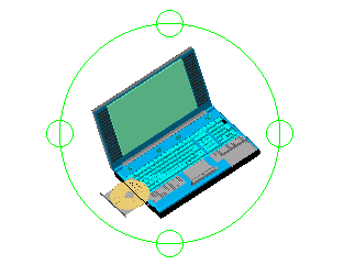
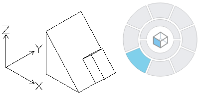
The View Navigator is a two ring widget displayed by default in the top-right corner of the graphics area. The View Navigator lets you switch between standard and isometric views of your model with a single click.
Use the ViewNavigator command to display the View Navigator.
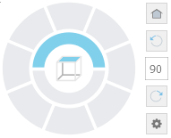
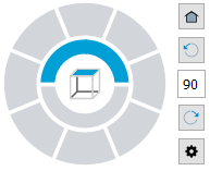
By default, the View Navigator is in an inactive state. It becomes active when you hover the mouse cursor over the View Navigator’s interface.
When the View Navigator is inactive, it is displayed with transparency. You can control the opacity level, as well as the location of the View Navigator in the graphics area.
You can switch to one of the available predefined views by clicking one of the ring sectors. The views can be relative to the active CCS or WCS. The cube’s position changes to reflect the orientation of the model.
Note: The cube reflects only standard views of the model. When you use interactive 3D viewing tools, such as RollView, the View Navigator hides the cube.
Hovering the cursor over the ring sectors of the View Navigator displays a tooltip. The tooltip describes the orientation of the view corresponding to the ring sector.
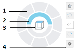
Elements of the View Navigator
|
|
The View Navigator’s Menu
The View Navigator’s menu provides quick access to Home view, projection modes, and View Navigator’s display settings.
To display the View Navigator’s menu:
- On the View Navigator‘s toolbar, click
 .
.
| Option | Description |
|---|---|
| Home | Quick access to the default view |
| Parallel | Switches the current view to parallel projection |
| Perspective | Switches the current view to perspective projection |
| Set Current View as Home | Specifies the current view as the Home view of the model |
| View Navigator Properties | Displays the View Navigator Properties dialog box where you can specify the position and the appearance of the View Navigator. |
| Help | Displays the corresponding Help topic |
Access
View Navigator’s toolbar:
The View Navigator’s Toolbar
The View Navigator’s toolbar lets you rotate the view by a specified angle and return to the default view.
| Icon | Description |
|---|---|
 |
Quick access to the default view |
 |
Rotates the view counterclockwise with a specified angle. By default, the rotation angle is 90°. |
 |
Lets you specify a rotation angle |
 |
Rotates the view clockwise with a specified angle. By default, the rotation angle is 90°. |
|
Displays the View Navigator’s menu |
Working with View Navigator Display Properties
Use the ViewNavigator command to turn the View Navigator on or off and to control where it displays.
You can control the appearance, visibility, and location of the View Navigator in the graphics area.
To display or hide the View Navigator:
- Type ViewNavigator.
- Specify an option:
- On. Displays the View Navigator.
- Off. Hides the View Navigator.
To specify the position of the View Navigator:
- Do one of the following:
- Type ViewNavigator and specify Properties.
- On the menu, click View > Display > View Navigator > Properties.
- If the View Navigator is visible, click and select View Navigator Properties from the menu.
- In the View Navigator Properties dialog box, specify the corner of the graphics area where you want to display the View Navigator.
To specify the View Navigator transparency level when it is inactive:
- Do one of the following:
- Type ViewNavigator and specify Properties.
- On the menu, click View > Display > View Navigator > Properties.
- If the View Navigator is visible, click and select View Navigator Properties from the menu.
- In the View Navigator Properties dialog box, in Inactive Opacity, specify the transparency either by entering a value in the text box or using the slider. Specify a value between 0 and 100% where 100% means opaque.
View Navigator Properties Dialog Box
This dialog box lets you control the visibility and the position of the View Navigator.
On-screen Position
Specifies the corner of the graphics area where the View Navigator displays.
Inactive Opacity
Specifies the opacity level of the View Navigator when it is inactive.
Use active CCS
When enabled, the views that you select using the View Navigator are relative to the active CCS. When disabled, the WCS is taken into account and 3D views from the View Navigator match standard isometric views.
Restore Defaults
Restores the default settings for the View Navigator.
Access
Command: ViewNavigator
Menu: View > Display > View Navigator > On
Ribbon: View > ViewTiles > View Navigator
Changing the View Orientation Using the View Navigator
The View Navigator is a user-friendly tool for changing the view orientation of a model.
- Switch between standard and isometric views of your model
- Control whether the isometric views are relative to the WCS or active CCS
- Set the projection mode
- Define a default view (Home View)
Switching between Standard and Isometric Views of Your Model
The View Navigator provides a set of predefined view orientations for quickly changing the view of the model.
- The Inner Ring lets you set top and bottom views.
- The Outer Ring provides a set of eight sectors for quickly switch between standard and isometric views of your model. Each sector of the Outer Ring corresponds to a view. When you click on a sector, the software moves the scene to the corresponding view.
Changing the View Projection Mode
The View Navigator provides two view projection modes:
- Parallel. A parallel projection is a projection in which projection lines are parallel to each other. Parallel projection provides an accurate view of an entity.
- Perspective. A perspective projection depends on the relative position of the view plane. Perspective projection does not preserve the size of the entity and therefore, gives a more realistic representation. The longer the distance, the smaller the entities.
To change the view projection mode:
- Display the View Navigator.
- Hover over the View Navigator, click and select one of the following options:
- Parallel.
- Perspective.
Using the Home View
The Home view is a special view of the model that you can store and apply it later, whenever it is necessary.
Using the View Navigator, you can define any view of the model as the Home view. Later, you can apply the saved view at any time.
To define the Home view:
- In the graphics area, set up a suitable 2D or 3D view. Use the Views command.
- Hover over the View Navigator, click and select Set Current View as Home from the menu.
To return to the Home view:
- Do one of the following:
- Hover over the View Navigator and click .
- Hover over the View Navigator, click and select Home from the menu.
- Hover over the View Navigator and click
Changing the View Orientation According to the Active CCS
Using the View Navigator, you can change the view orientation within the active CCS or WCS.
To change the view orientation according to the CCS:
- In the graphics area, set up a suitable CCS.
- Hover over the View Navigator, click and select View Navigator Properties from the menu.
- In the View Navigator Properties dialog box, select Use active CCS.
Example:
WCS

CCS

To control CCSs, use the CCS and CSStyle commands.