Introducción
XtraTools provide a set of additonal commands to increase productivity in many ways in design process.
XtraTools Commands Help is divided into these sections:
- Drafting Tools
- Annotation Tools
- Dimension Tools
- Blocks and References Tools
- Editing Tools
- View Tools
- Utilities
See XtraTools Commands Reference for a complete list of commands.
Drafting Tools
This section discusses:
Creating Breaklines
Use the BreakLine command to draw a line with a breakline symbol. You can define your own breakline symbols to use with this command.
A breakline symbol definition includes the symbol name, the geometry, and the locations where the symbol will connect with the line. After you create a breakline symbol, you can use it in the same or a different drawing.
You can specify the size of the symbol and the length of the line to be added to selected points.
To create a new breakline symbol:
- Start a new drawing.
- Draw the breakline symbol.

- Use the Point command (Multiple option) to create two point objects defining the location where the breakline symbol will connect with the line.

- Save the drawing in the ..\XtraTools\BreakLine folder of the installation folder.
To create a breakline symbol and apply it to the current line:
- Draw the breakline symbol.

- Do one of the following:
- On the ribbon, click XtraTools > Draw > Break Line.
- On the menu, click XtraTools > Draw > Break Line.
- Type Breakline.
- Type Settings and press Enter.
- In the dialog box, do the following:
- In Name, type the name of the new breakline symbol.
- Click Specify entities
 to specify the entities to use as breakline.
- In the graphics area, define the breakline symbol:
- Select the entities drawn in the first step.
- Specify two points defining the location where the breakline symbol will connect with the line.

- Specify a point to start the line segment.
- Specify a point to end the line segment.
- Press Enter to use Midpoint or click a point on the line segment to define the symbol location.
 Note: Breakline symbols created during the BreakLine command are automatically saved in the ..\XtraTools\BreakLine folder of the installation folder.
To create a breakline:
- Do one of the following:
- On the ribbon, click XtraTools > Draw > Break Line.
- On the menu, click XtraTools > Draw > Break Line.
- Type BreakLine.
- In the graphics area, specify:
- A point to start the line segment.
- A point to end the line segment.
- Press Enter to use Midpoint or click a point on the line segments to define the symbol location.
To create a breakline with custom breakline symbol:
- Do one of the following:
- On the ribbon, click XtraTools > Draw > Break Line.
- On the menu, click XtraTools > Draw > Break Line.
- Type Breakline.
- Type Settings and press Enter.
- In the dialog box, click Browse.
- Select the .dwg file containing a previously defined breakline symbol and press Open.
The preview area displays the selected symbol.
- Click OK.
- In the graphics area, specify:
- A point to start the line segment.
- A point to end the line segment.
- Press Enter to use Midpoint or click a point on the line segments to define the symbol location.

Access
Command: Breakline
Menu: XtraTools > Draw > Break Line
Ribbon: XtraTools > Draw > Break Line
Creating Patterns of Hatches
Use the PatternHatch command to create hatches using block entities, images, external references or masks.
You can save configurations as favorites for later use in other projects and drawings.
 Note: You cannot save the selected boundary, as it depends of the drawing. Thus you can apply the hatch to any other shapes and boundaries.
To create a pattern of hatches from blocks, images, or external references:
- Do one of the following:
- On the ribbon, click XtraTools > Draw > Pattern Hatch.
- On the menu, click XtraTools > Draw > Pattern Hatch.
- Type PatternHatch.
- In the dialog box, in Type, select the pattern type to use for the hatch:
- Block. Lets you select a predefined block and use it for the hatch pattern.
- Image. Lets you select an image.
- External reference. Lets you select an external reference file for the hatch pattern.
- Mask. Lets you use a mask object for the hatch pattern.
- In Pattern, click Browse
 and select the block, image or external reference file to use as pattern.
 - In Size and position, specify options:
- Specify X and Y scale value by which to scale the hatch pattern.
- Specify the horizontal and vertical distance between patterns.
- Specify the origin or initial pattern position. You can use Specify entities
 to select the origin in the graphics area.
 - Specify the rotation angle of the pattern. You can use Rotation angle
 to define the rotation angle in the graphics area.
 Note: You can use Extract from entity to extract the pattern type and the name from an entity from the drawing. Thus you can place a pattern on the drawing and create a hatch with it.
 - Select a method to specify the boundaries:
-
Specify entities
 . Lets you select the entities that form the boundary.
 -
Specify points
 . Lets you click points in enclosed areas to define the boundaries.
 -
Rebuild boundary
 . Replaces a boundary after removing (enabled only when using the EditHatch command).
 -
Delete boundary entities
 . Removes boundaries from the set of entities that form the boundaries.
 -
Highlight boundary entities
 . Displays the boundaries in the drawing.
-
Specify entities
- In Type of entities, specify if you want to create the hatch as an anonymous block or as a group of entities. If Mask is selected the hatch can only be created as block entity.
 It is recommended to create the hatch as block so you can edit it. You cannot edit groups of entities.
 - In Limits, define the hatch behavior at boundary:
- Cut entities: When enabled, cuts the pattern entities that surpass the specified boundary. When disabled the pattern entities can surpass the limits. For example, you can use this option when representing trees on a terrain and you do not want the trees representations to be cut.
- Draw surpassing entities: When disabled, the entities that surpass the boundary limits are not displayed. For example, you can use this option when representing parking places in a parking and you do not want to display any place that surpasses the defined boundary.
- In Tolerance for curves, specify the precision for the approximation of curved boundaries (the maximum distance between the midpoint of any given segment and the arc).
 Note: When working with blocks or images, standard limiter boundaries are used. Standard limiter boundaries can only contain straight segments, so when the boundary contains curved segments it must be converted to a similar shape using straight segments.
 - Click Preview to check the resulting hatch without creating it.
 You can preview the result as many times as necessary.
 - Click OK.
To create a pattern of hatches from mask:
- Do the following:
- On the ribbon, click XtraTools > Draw > Pattern Hatch.
- On the menu, click XtraTools > Draw > Pattern Hatch.
- Type PatternHatch.
- In the dialog box, in Type, select Mask.
- Select a method to specify the boundaries:
-
Specify entities
 . Lets you select the entities that form the boundary.
 -
Specify points
 . Lets you click points in enclosed areas to define the boundaries.
 -
Rebuild boundary
 . Replaces a boundary after removing (enabled only when using the EditHatch command).
 -
Delete boundary entities
 . Removes boundaries from the set of entities that form the boundaries.
 -
Highlight boundary entities
 . Displays the boundaries in the drawing.
-
Specify entities
- In Limits, define the hatch behavior at the boundary:
- Cut entities: When enabled, cuts the pattern entities that surpass the specified boundary. When disabled the pattern entities can surpass the limits. For example, you can use this option when representing trees on a terrain and you do not want the trees representations to be cut.
- Draw surpassing entities: When disabled, the entities that surpass the boundary limits are not displayed. For example, you can use this option when representing parking places in a parking and you do not want to display any place that surpasses the defined boundary.
- In Tolerance for curves, specify the precision for the approximation of curved boundaries (the maximum distance between the midpoint of any given segment and the arc).
 Note: When working with blocks or images, standard limiter boundaries are used. Standard limiter boundaries can only contain straight segments. When the boundary contains curved segments it must be converted to a similar shape using straight segments.
To define a pattern and save it in favorites:
- Do one of the following:
- On the ribbon, click XtraTools > Draw > Pattern Hatch.
- On the menu, click XtraTools > Draw > Pattern Hatch.
- Type PatternHatch.
- In the dialog box, in Type, select the pattern type to use for the hatch: Block, Image, External reference, or Mask.
- In Pattern, click Browse
 and select the block, image, or external reference to use as pattern.
 - Specify options for the pattern and specify the boundary. See To create a pattern of hatches from blocks, images or external references.
- In the Favorites section, in Name, type the name of the configuration.
- Click Save favorite
 .
.
 You can save in Favorites as many predefined configurations as you need.
To delete a pattern configuration from favorites:
- In the dialog box, from the Name list, select the pattern configuration to remove from favorites.
- Click Remove favorite
 .
.
Example
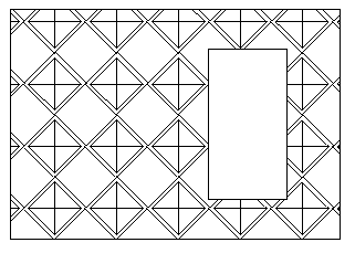
In this example, a block is used to hatch the following closed area.
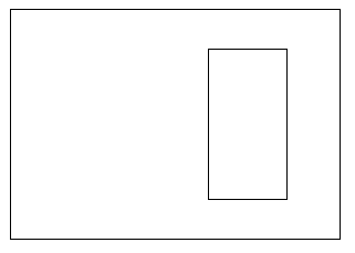
Draw the geometric entities and define the block.

Use the following setings:
- Enable Cut entities.
- Enable Draw surpassing entities.
Area hatched with the defined block:
Access
Command: PatternHatch
Menu: XtraTools > Draw > Pattern Hatch
Ribbon: XtraTools > Draw > Pattern Hatch
Annotation Tools
This section discusses:
- Creating and Modifying Curved Text
- Converting SimpleNotes
- Adding a Numbering Sequence to Text Entities
- Creating a Frame Around a Text
- Creating a Text Mask
- Removing a Text Mask
- Modifying Case Style
- Modifying Text Justification
- Modifying Text Orientation
- Fitting Text Width
- Exploding Annotations
Creating and Modifying Curved Text
Use the CurvedText command to place a text along an arc.
You can control the text direction and location and modify the text format and style. Any change in dialog box is automatically visible on the drawing, so you can see the resulting text before closing the dialog box.
 Note: The CurvedText command does not work on splines, circles, ellipses, and polylines.
To create a text along an arc:
- Do one of the following:
- On the ribbon, click XtraTools > Annotation > Curved Text.
- On the menu, click XtraTools > Annotation > Curved Text.
- Type CurvedText.
- Select the arc along which you want to write the text.
- In the dialog box, type the text.
- Optionally, change the text settings. See To modify a text along an arc.
- Click OK.
To modify a text along an arc:
- Do one of the following:
- On the ribbon, click XtraTools > Annotation > Curved Text.
- On the menu, click XtraTools > Annotation > Curved Text.
- Type CurvedText.
- Select the curved text. The properties dialog box appears.
 Note: Any change in the dialog box is automatically visible on the drawing.
 - In the dialog box, modify the existing Text displayed along the arc. Optionally, define underline, bold and italic properties.
- In Text settings, specify the text position relative to the arc.
- In Text formatting, specify text style, font, color, height and space between characters.
- In Offset from, specify the offset relative to the center and each side of the arc.
- Click OK.
Access
Command: CurvedText
Menu: XtraTools > Annotation > Curved Text
Ribbon: XtraTools > Annotation > Curved Text
Converting SimpleNotes
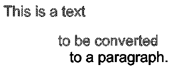
Use the ConvertSimpleNotes command to transform one or multiple selected SimpleNotes entities to a text paragraph.
To convert a set of SimpleNotes to a text paragraph:
- Do one of the following:
- On the ribbon, click XtraTools > Annotation > Convert SimpleNotes.
- On the menu, click XtraTools > Annotation > Convert SimpleNotes.
- Type ConvertSimpleNotes.
- In the dialog box, make the conversion settings:
- In Ordering, specify the sorting mode to use for the selected text entities to build the paragraph. The following options are available:
- Selection set. Sorts the texts in the same order as they were selected.
- Top-down. Sorts the texts based on their insertion points, from top to bottom.
- Alphabetical. Sorts the texts alphabetically.
- In Format, select the options corresponding to the text properties to maintain in the text style.
- Create word-wrap text: Generates the paragraph in word-wrap format. All texts are placed in a single line separated with a blankspace.
- In Ordering, specify the sorting mode to use for the selected text entities to build the paragraph. The following options are available:
- Click OK.
- In the graphics area, specify the SimpleNotes entities to convert.
- Press Enter.
A single SimpleNote entity replaces the previously selected SimpleNotes.

Access
Command: ConvertSimpleNotes
Menu: XtraTools > Annotation > Convert SimpleNotes
Ribbon: XtraTools > Annotation > Convert SimpleNotes
Adding a Numbering Sequence to Text Entities
Use the NumberText command to insert sequential numbering to selected text entities.
You can add the sequence as a prefix or as a suffix. Additionally, you can overwrite the existing text.
To add numbering sequence to selected text entities:
- Do one of the following:
- On the ribbon, click XtraTools > Annotation > Number Text.
- On the menu, click XtraTools > Annotation > Number Text.
- Type NumberText.
- In the dialog box, select the sorting method:
- Position X. Sorts the text entities by X coordinate of the insertion point of each text entity.
- Position Y. Sorts the text entities by Y coordinate of the insertion point of each text entity.
- Select order. Sorts the text entities according to the selection order.
- Relative to one point. Sorts the text entities by the distance of each entity to a given point.
- Relative to two points. Sorts the text entities by the distance of each entity to a theoretical rectangle defined by two given points.
- Specify options:
- In Text placement, specify how to apply the sequential numbering:
- Prefix. Places the sequence as prefix of selected text entities.
- Suffix. Places the sequence as suffix of selected text entities.
- Replace. Lets you specify the string from the text entities, which you want to replace with the sequential value.
- Overwrite. Sequential value replaces all current text of entities.
- In Text format, specify an additional prefix and suffix to the number sequence (not the original texts).
- In Sorting direction, select an ascending or a descending order.
- In Counter, specify the counting settings:
- Initial value. First number of the sequence.
- Increment. The difference between the numbers in the sequence.
- Digits. Number of digits of each sequence number.
- In Text placement, specify how to apply the sequential numbering:
- Click OK.
- In the graphics area, select the text entities.
- Press Enter.
Examples:
Initial value = 1, Increment = 1, Text placement: Prefix;
Prefix = N°, Suffix = x1.

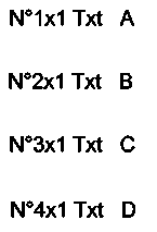
Initial value = 1, Increment = 2, Text placement: Overwrite;
Prefix = N°, Suffix = x1.


Access
Command: NumberText
Menu: XtraTools > Annotation > Number Text
Ribbon: XtraTools > Annotation > Number Text
Creating a Frame Around a Text
Use the TextFrame command to create a frame around specified text entities.
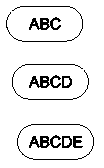
The frames can have the following shapes:
- Slot of constant or variable size
- Rectangle of constant or variable size
- Circle of constant or variable diameter
You can create frames with a transparent or solid background.
Variable frames adjust their size according to the size of the selected text. Frames with constant size surround the selected texts with frames that have the same width or height.
Examples:
- Slots with constant width
- Slots with variable width

To create a text frame of constant size:
- Do one of the following:
- On the ribbon, click XtraTools > Annotation > Text Frame.
- On the menu, click XtraTools > Annotation > Text Frame.
- Type TextFrame.
- In the dialog box, in Type, select the shape of the frame: Slot, Rectangle, or Circle.
- In Dimensions, specify options:
- Select Constant.
- Type the offset of the frame.
- For a slot or a rectangular frame, in Maintain Constant, specify the frame side that must remain constant. You can keep the width, the height, or both.
- Optionally, in Background, set a solid background:
- Select Hatch.
- In Color, select a color for the background.
- Click OK.
- In the graphics area, specify the text entities for which you want to create the frames and press Enter.
To create a text frame of variable size:
- Do one of the following:
- On the ribbon, click XtraTools > Annotation > Text Frame.
- On the menu, click XtraTools > Annotation > Text Frame.
- Type TextFrame.
- In the dialog box, in Type, select the shape of the frame: Slot, Rectangle, or Circle.
- In Dimensions, specify options:
- Select Variable.
- Type the offset of the frame.
- Optionally, in Background, set a solid background:
- Select Hatch.
- In Color, select a color for the background.
- Click OK.
- In the graphics area, select the text entities for which you want to create the frames and press Enter.
Access
Command: TextFrame
Menu: XtraTools > Annotation > Text Frame
Ribbon: XtraTools > Annotation > Text Frame
Creating a Text Mask
Use the TextMask command to place a blank area behind specified text entities.
Optionally, you can:
- Define a margin around the text.
- Apply a solid mask to the text. You can select a background color for the text.
- Modify the properties of an existing text mask.
 Note: The text and the mask act as an entity. You can move, copy, or delete them together.
- To remove masks from text entities, use the TextUnMask command.
- To separate the text from the mask, use the Explode tool.
To create a default text mask:
- Do one of the following:
- On the ribbon, click XtraTools > Annotation > Text Mask.
- On the menu, click XtraTools > Annotation > Text Mask.
- Type TextMask.
- In the graphics area, specify the text entities to mask.
- Press Enter.
To create a custom text mask:
- Do one of the following:
- On the ribbon, click XtraTools > Annotation > Text Mask.
- On the menu, click XtraTools > Annotation > Text Mask.
- Type TextMask.
- Press Enter.
- In the dialog box, specify options. See To edit a text mask.
- Click OK.
- In the graphics area, specify the text entities to mask.
- Press Enter.
To apply a solid mask with background:
- Do one of the following:
- On the ribbon, click XtraTools > Annotation > Text Mask.
- On the menu, click XtraTools > Annotation > Text Mask.
- Type TextMask.
- Press Enter.
- In the dialog box, specify options:
- In Entity type, select Solid.
- In Background, select the color.
- Click OK.
- In the graphics area, specify the text entities to mask.
- Press Enter.
To edit a text mask:
- Do one of the following:
- On the ribbon, click XtraTools > Annotation > Text Mask.
- On the menu, click XtraTools > Annotation > Text Mask.
- Type TextMask.
- In the graphics area, specify the masked text to edit.
-
In the dialog box, specify options:
- In Entity type, select the type of mask:
- Mask. Creates a rectangular mask entity that has the color of the background.
- 3D Face. Creates a 3D face entity.
- Solid. Creates a 2D solid entity in a specified color.
- In Dimensions, specify the offset value (the space around the text).
- In Background, select the color of the text background. This option is available only for solid text masks.
- In Entity type, select the type of mask:
- Click OK.
Examples:
Text over hatch

Masked text over hatch

Masked text over hatch, with solid background

Access
Command: TextMask
Menu: XtraTools > Annotation > Convert SimpleNotes
Ribbon: XtraTools > Annotation > Convert SimpleNotes
Removing Text Masks
Use the TextUnMask command to remove the masks assigned to selected text entities using the TextMask command.
To remove the mask:
- Do one of the following:
- On the ribbon, click XtraTools > Annotation > Text Unmask.
- On the menu, click XtraTools > Annotation > Text Unmask.
- Type TextUnMask.
- In the graphics area, specify the text entities from which you want to remove the masks.
- Press Enter.
Access
Command: TextUnMask
Menu: XtraTools > Annotation > Text Unmask
Ribbon: XtraTools > Annotation > Text Unmask
Modifying Case Style
Use the EditTextCase command to modify the case style of selected SimpleNotes, BlockAttribute, or Dimension text.
To modify the case style of a text:
- Do one of the following:
- On the ribbon, click XtraTools > Annotation > Edit Text Case.
- On the menu, click XtraTools > Annotation > Edit Text Case.
- Type EditTextCase.
- In the graphics area, specify the text entities and press Enter.
- In the dialog box, select the case style to apply to selected entities:
- Sentence. Capital letter on the first sentence character.
- Lowercase. Changes a text written in upper-case characters into a lower-case text.
- Uppercase. Changes a text written in lower-case characters into a upper-case text.
-
Title. Changes the first character of every word of the text into upper-case.
- Toggle. Changes lower-case characters into upper-case characters and vice versa.
- Click OK.
Access
Command: EditTextCase
Menu: XtraTools > Annotation > Edit Text Case
Ribbon: XtraTools > Annotation > Edit Text Case
Modifying Text Justification
Use the EditTextJustification command to modify the justification point of selected text, paragraph, or attribute entities.
 Note: The text position does not change.
To modify the text justification:
- Do one of the following:
- On the ribbon, click XtraTools > Annotation > Edit Text Justification.
- On the menu, click XtraTools > Annotation > Edit Text Justification.
- Type EditTextJustification.
- In the graphics area, specify the text entities.
- Press Enter.
- Specify the justification option:
- Start. Start point of the text baseline
- Center. Center point of the text baseline
- Middle. Middle point of the text
- Right. Right point of the text baseline
-
TL. Top left point of the text

-
TC. Top center point of the text

-
TR. Top right point of the text

-
ML. Middle left point of the text

-
MC. Middle center point of the text

-
MR. Middle right point of the text

-
BL. Bottom left point of the text

-
BC. Bottom center point of the text

-
BR. Bottom right point of the text

- Press Enter.
Access
Command: EditTextJustification
Menu: XtraTools > Annotation > Edit Text Justification
Ribbon: XtraTools > Annotation > Edit Text Justification
Modifying Text Orientation
Use the EditTextOrientation command to rotate selected text, paragraph, or attribute entities keeping their current position.
Additionally, the command provides the More Readable option that allows you to automatically rotate the selected text, paragraph, or attribute entities so that their orientation is as close as possible to horizontal read. For example, a horizontal upside-down text becomes horizontal right-side up.
To modify the text orientation:
- Do one of the following:
- On the ribbon, click XtraTools > Annotation > Edit Text Orientation.
- On the menu, click XtraTools > Annotation > Edit Text Orientation.
- Type EditTextOrientation.
- In the graphics area, specify the text entities.
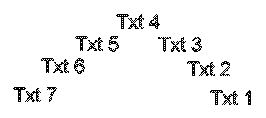
- Press Enter.
- Type the absolute rotation angle (for example, 90) and press Enter.
The selected text is rotated.
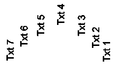
To modify text orientation for more readability:
- Do one of the following:
- On the ribbon, click XtraTools > Annotation > Edit Text Orientation.
- On the menu, click XtraTools > Annotation > Edit Text Orientation.
- Type EditTextOrientation.
- In the graphics area, specify the text entities.
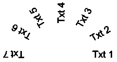
- Press Enter.
- Specify the More Readable option and press Enter.
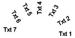
 Note: If the selected entities are in the right position, the More Readable option does not rotate them.
Access
Command: EditTextOrientation
Menu: XtraTools > Annotation > Edit Text Orientation
Ribbon: XtraTools > Annotation > Edit Text Orientation
Fitting Text Width
Use the FitText command to resize the width of a text entity to fit between two selected points.
 FitText accepts only SimpleNote entities.
To fit a text between two selected points:
- Do one of the following:
- On the ribbon, click XtraTools > Annotation > Fit Text.
- On the menu, click XtraTools > Annotation > Fit Text.
- Type FitText.
- In the graphics area, specify the SimpleNote.
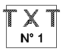
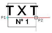
- In the graphics area, specify the endpoint. The command uses the current starting point of the text entity.
– or –
In the graphics area, specify two points defining the location and the new length of the text entity.
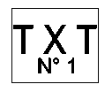
The width of the text entity fits within the specified width:
Access
Command: FitText
Menu: XtraTools > Annotation > Fit Text
Ribbon: XtraTools > Annotation > Fit Text
Exploding Annotations
Use the ExplodeText command to convert annotations into PolyLines, which represent the text outline.
You can explode Notes, SimpleNotes, text of Leader entities, and BlockAttribute Definitions.
You can base the TextStyle of the annotations on TrueType fonts and SHX files.
To explode annotations:
- Do one of the following:
- On the ribbon, click XtraTools > Annotation > Explode Text.
- Type ExplodeText.
- Specify the annotation to explode.
The specified annotations are converted into closed PolyLines.
![]() Use the Explode command to explode other complex entities (for example, Blocks).
Use the Explode command to explode other complex entities (for example, Blocks).
Access
Command: ExplodeText
Ribbon: XtraTools > Annotation > Explode Text
Dimension Tools
This section discusses:
Exporting Dimension Styles
Use the ExportDimensionStyle command to export the dimension styles from the current drawing to an external ASCII file (with .dim extension).
 You can use ExportDimensionStyle and ImportDimensionStyle to transfer dimension styles from one drawing to another.
To export dimension styles:
- Do one of the following:
- On the ribbon, click XtraTools > Dimensions > Export Dimension Style.
- On the menu, click XtraTools > Dimensions > Export Dimension Style.
- Type ExportDimensionStyle.
- In the dialog box, select the dimension styles to export.
 Clicking a style displays the dimension variables defined for that style.
 - In Options, select one of the following:
- TextStyle name only. Saves only the name of the styles. When importing the styles, the software will create the style names that do not exist.
- Full TextStyle information. Saves all properties of the styles, to recreate them when importing styles.
- Click Export.
 Note: The command generates a .dim file which you can use with ImportDimensionStyle command.
Access
Command: ExportDimensionStyle
Menu: XtraTools > Dimensions > Export Dimension Style
Ribbon: XtraTools > Dimensions > Export Dimension Style
Importing Dimension Styles
Use the ImportDimensionStyle command to import dimension styles and their settings from an ASCII file (with .dim extension).
 You can use ExportDimensionStyle and ImportDimensionStyle to transfer dimension styles from one drawing to another.
To import dimension values:
- Do one of the following:
- On the ribbon, click XtraTools > Dimensions > Import Dimension Styles.
- On the menu, click XtraTools > Dimensions > Import Dimension Styles.
- Type ImportDimensionStyle.
- In the dialog box, click Browse.
- Select the .dim file containing dimension styles to import. The styles that you can import appear in the left list.
 Clicking each style displays the dimension variables defined for that style.
 - From the left list, select the dimension styles to import.
- In the Option section, select one of the following:
- Keep existing style. Imports only dimension styles already defined in the drawing.
- Overwrite existing style. Imports all styles whether they exist in the drawing or not.
- Click OK.
Access
Command: ImportDimensionStyle
Menu: XtraTools > Dimensions > Import Dimension Styles
Ribbon: XtraTools > Dimensions > Import Dimension Styles
Blocks and References Tools
This section discusses:
- Scaling Blocks
- Replacing Blocks One by Another
- Replacing Blocks by References
- Replacing BlockAttribute Values
- Redefining BlockAttributes
- Importing BlockAttribute Values
- Getting Block Information
- Displaying the Properties of a Block Entity
Scaling Blocks
Use the ScaleBlock command to scale blocks relative to their insertion point.
You can select the scale as an absolute value or relative to the current scale factor.
To scale blocks:
- Do one of the following:
- On the ribbon, click XtraTools > Block > Scale Block.
- On the menu, click XtraTools > Block > Scale Block.
- Type ScaleBlock.
- In the graphics area, specify the blocks to scale.
- Specify the scale mode:
- Absolute (final). Specifies the scale as an absolute value.
- Relative (multiply). Specifies the scale as a value relative to the current scale factor.
- Type the scale value in X axis and press Enter.
- Type the scale value in Y axis and press Enter.
Access
Command: ScaleBlock
Menu: XtraTools > Block > Scale Block
Ribbon: XtraTools > Block > Scale Block
Replacing Blocks One by Another
Use the ReplaceBlock command to replace all instances of a specified Block by another specified block. The command lets you to purge the definitions of the replaced blocks.
To replace block instances by another block:
- Do one of the following:
- On the ribbon, click XtraTools > Block > Replace Block.
- On the menu, click XtraTools > Block > Replace Block.
- Type ReplaceBlock.
- In the dialog box, do the following:
- In Blocks to replace, select the name of the block to replace.
- In Replacing block, select the name of the replacement Block.
- Optionally, select the following options:
- Clean unreferenced items. Purges the definitions of replaced Blocks.
-
Update BlockAttributes for Block replacements. Updates all instances of Blocks with new or modified BlockAttributes.
 Note: You can change or add BlockAttributes to an existing Block definition by redefining the Block using the MakeBlock command. You can also modify the definition and properties of BlockAttributes with the EditComponent command. Both commands update the geometry of all instances of the redefined Block, but they do not automatically update the BlockAttributes that have been modified.
- Click Apply.
Access
Command: ReplaceBlock
Menu: XtraTools > Block > Replace Block
Ribbon: XtraTools > Block > Replace Block
Replacing Blocks by References
Use the ReplaceBlockByReference command to replace all instances of a specified Block by instances of an externally referenced drawing (Reference). The command lets you to specify the Blocks and the file to be used as external reference.
To replace Blocks by References:
- Do one of the following:
- On the ribbon, click XtraTools > Block > Replace Block By Reference.
- On the menu, click XtraTools > Block > Replace Block By Reference.
- Type ReplaceBlockByReference.
- In the dialog box, in Blocks to replace, specify the block to replace:
- Select the name of the block to replace from the list.
– or –
- Click Specify blocks
 .
. - Select the Specify entities option, select the block instances in the graphics area, and press Enter to complete the selection.
- Select the name of the block to replace from the list.
- In the dialog box, in Replacing reference, click Browse.
- In the Select folder dialog box, specify the following:
- Navigate to the folder which contains the replacing drawing file.
- Click Select folder.
- In Replacing reference, select the replacing drawing file.
- Optionally, select the Clean unreferenced items option to purge the definitions of replaced Blocks.
- Click Apply.
Access
Command: ReplaceBlockByReference
Menu: XtraTools > Block > Replace Block by Reference
Ribbon: XtraTools > Block > Replace Block by Reference
Replacing BlockAttribute Values
Use the ReplaceBlockAttributeValues to globally modify the values of the BlockAttributes of all instances of the selected Blocks.
You can replace the attribute values automatically, all at once, by selecting them one by one.
To replace BlockAttribute values:
- Do one of the following:
- On the ribbon, click XtraTools > Block > Replace BlockAttribute Values.
- On the menu, click XtraTools > Block > Replace BlockAttribute Values.
- Type ReplaceBlockAttributeValues.
- Specify a Block, using one of the following methods:
- In the graphics area, specify the block.
– or –
- Type Block name and press Enter.
- In the graphics area, specify the block.
- Specify the block attribute for which you want to modify the value.
- Type the new value of the attribute and press Enter. The tool counts the instances of the selected block.
- To specify whether to replace the values for all attributes, type Yes or No.
- If you specified No:
- In the graphics area, specify the blocks for which you want to modify the attribute values.
- Press Enter.
Access
Command: ReplaceBlockAttributeValues
Menu: XtraTools > Block > Replace BlockAttribute Values
Ribbon: XtraTools > Block > Replace BlockAttribute Values
Redefining BlockAttributes
Use the RedefineBlockAttribute command to redefine the shape of a Block and update the list of associated BlockAttributes.
The BlockAttributes are updated, as follows:
- Existing attributes that are included in the new definition keep their original values.
- Existing attributes that are not included in the new Block definition are deleted.
- New attributes from the new Block definition will have their default values.
 Note: You cannot update constant BlockAttributes.
To redefine BlockAttributes:
- Do one of the following:
- On the ribbon, click XtraTools > Block > Redefine BlockAttributes.
- On the menu, click XtraTools > Block > Redefine BlockAttributes.
- Type RedefineBlockAttribute.
- Specify the block to redefine, using one of the following methods:
- Type the name of the block and press Enter.
– or –
- Press Enter. In the graphics area, specify an instance of the Block to redefine.
- Type the name of the block and press Enter.
- In the graphics area, specify the entities to include in the new Block definition.
 Note: The selection for the new Block definition must include at least one BlockAttribute.
 - Press Enter.
- Specify the base point of the new Block.
The definition of all insertions of the specified Block will contain the new entities, the new base point and the new BlockAttributes.
Access
Command: RedefineBlockAttribute
Menu: XtraTools > Block > Redefine BlockAttribute
Ribbon: XtraTools > Block > Redefine BlockAttribute
Importing BlockAttribute Values
Use the ImportBlockAttribute command to import BlockAttribute values from a previously exported ASCII file. See Exporting BlockAttributes.
 You can use BlockAttributeOutput and ImportBlockAttribute to change BlockAttribute values of the selected Blocks. Additionally, ImportBlockAttribute allows you to modify the values before importing them. The command will use the current values, not the values from the imported file.
The command reads the imported file, searches the drawing for Block instances with the same handle as in the file and applies the new attribute values to those blocks. If a Block is missing, the command lets you to select other blocks to apply the attributes.
To import BlockAttribute values:
- Do one of the following:
- On the ribbon, click XtraTools > Block > Import BlockAtributes.
- On the menu, click XtraTools > Block > Import BlockAttributes.
- Type ImportBlockAttributes.
- In the dialog box, click Browse.
- Select the attributes file to import and click OK.
The dialog box displays the imported values in the list.
 You can sort the list according to the entries of a column by clicking the column header. Sequential clicks switch between ascending and descending order.
 - In the list, modify the values of the attributes. Use one of the following methods:
- Modify individual values: Double-click the cell containing the BlockAttribute to modify and type the new value.
- Find and replace:
- Select the rows you want to modify.
- In Find what, type the text or the value to find.
- In Replace with, type the text or value to replace the search string or value.
- Click Replace.
The list displays the new values.
- In the list, select the BlockAttributes to import in the current drawing.
Enable Select all to select all blocks in the list.
 The command uses the current list values, not the imported values.
 - Click OK.
Access
Command: ImportBlockAttributes
Menu: XtraTools > Block > Import BlockAttributes
Ribbon: XtraTools > Block > Import BlockAttributes
Retrieving Block Information
Use the GetBlockInfo command to count the instances of the Blocks used in the drawing.
You can count the instances of all blocks in the drawing or only for a selection of blocks.
The list of blocks and the number of instances found in the drawing (or within the selection set) appears in a dialog box.
You can sort the list according to the names or the number of instances.
You can also specify whether you want to include nested blocks (blocks within other blocks) into block count.
Optionally you can:
- Export list to a file: Exports the list to an ASCII file.
- Export list to a table in drawing: Generates a table in drawing with list contents.
To retrieve information about blocks in the drawing:
- Do one of the following:
- On the ribbon, click XtraTools > Block > Get Block Info.
- On the menu, click XtraTools > Block > Get Block Info.
- Type GetBlockInfo.
- In the graphics area, specify the Blocks for which you want to count the instances and press Enter.
- Do one of the following:
- Specify Yes to count all instances of selected blocks within the entire drawing.
- Specify No to count all instances of selected blocks within the selection.
In the dialog box, the Block names and the number of ther instances display.
- In the dialog box, click the column headers to sort the entries by their name or the number of instances. Repeated clicks switch between ascending and descending order.
- Optionally, select Include nested blocks.
- Click Close.
To export the block information list to a table in the drawing:
- Do one of the following:
- On the ribbon, click XtraTools > Block > Get Block Info.
- On the menu, click XtraTools > Block > Get Block Info.
- Type GetBlockInfo.
- In the graphics area, specify the blocks for which you want to count the instances and press Enter.
- In the dialog box, click the column headers to sort the list as needed.
- Optionally, select Include nested blocks.
- Click Export list to a table in drawing.
This action closes the dialog box.
- In the grafics area, specify the insertion point for the table.
To export the block information list to a file:
- Do one of the following:
- On the ribbon, click XtraTools > Block > Get Block Info.
- On the menu, click XtraTools > Block > Get Block Info.
- Type GetBlockInfo.
- In the graphics area, specify the blocks for which you want to count the instances and press Enter.
- In the dialog box, click the column headers to sort the list as needed.
- Optionally, enable Include nested blocks.
- Click Export list to a file.
This action closes the dialog box.
- Specify folder and name of the file and click Save.
Access
Command: GetBlockInfo
Menu: XtraTools > Block > Get Block Info
Ribbon: XtraTools > Block > Get Block Info
Displaying the Properties of a Block Entity
Use the GetNestedProperties command to display the properties of an entity of a Block or a Reference.
To display the properties of a Block entity:
- Do one of the following:
- On the ribbon, click XtraTools > Block > Get Nested Properties.
- On the menu, click XtraTools > Block > Get Nested Properties.
- Type GetNestedProperties.
- In the graphics area, select an entity of a block (line, text, attribute, etc.).
A dialog box displays the entity properties: entity type, Layer, LineColor, and LineStyle. For a text entity, the properties include the TextStyle information.
Example:
The command identifies the selected entity as circle.
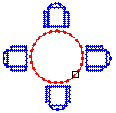
The dialog box displays the Circle properties:
Entity: CIRCLE
Layer: 0
LineColor: Red
LineStyle: ByLayer
Access
Command: GetNestedProperties
Menu: XtraTools > Block > Get Nested Properties
Ribbon: XtraTools > Block > Get Nested Properties
Herramientas de edición
En esta sección se explica:
- Aplanamiento automático de dibujos
- Creación de varias copias
- Equidistanciado de entidades seleccionadas
- Modificación del orden de dibujo de entidades por color
Aplanamiento automático de dibujos
Utilice el comando Aplanar para aplanar los dibujos automáticamente.
Puede aplanar todas las entidades del dibujo o solo un subconjunto específico. Por ejemplo, el comando SelecciónInteligente le permite seleccionar conjuntos de entidades por categoría.
Nota: Después de aplanar, las entidades 2D resultantes conservan sus capas originales, estilos de línea y colores.
Podrá realizar lo siguiente:
- Crear una representación en 2D a partir de un modelo 3D
Cuando se aplana una vista en 2D o una vista en 3D de un modelo en 3D, el comando proyecta las entidades en 3D especificadas en el plano de visualización actual. La vista de modelo se crea con entidades en 2D.
- Corregir dibujos que tengan coordenadas Z desconocidas
Mientras trabaja en un dibujo, puede que tenga propiedades como espesor, elevación u otra propiedad no representativa para una entidad 2D.
 Utilice una de las siguientes herramientas para comprobar si el dibujo tiene coordenadas Z:
Nota: La pérdida de precisión puede ocurrir en las siguientes situaciones:
- Aplanamiento sin líneas ocultas
- Aplanamiento de una vista en perspectiva
Propiedades que pueden agregar elevación o la coordenada Z a una entidad 2D:
| Entidad | Propiedades |
|---|---|
| Polilínea, rayado, nube | ELEvación |
| Línea | Inicio Z, finalización Z |
| Círculo, arco, elipse | Z central |
| Spline | Punto de ajuste Z |
| Entidades anotativas | Posición Z |
Para aplanar un dibujo con coordenadas Z desconocidas:
- Realice una de las siguientes acciones:
- En el menú, haga clic en XtraTools > Modificar > Aplanar.
- En la cinta, haga clic en XtraTools > Modificar > Aplanar.
- En la cinta, haga clic en Inicio > Herramientas > Aplanar.
- Escriba Aplanar.
- Seleccione todas las entidades del dibujo con una coordenada Z diferente de 0.
 Como alternativa, puede utilizar el comando SelecciónInteligente para seleccionar las entidades con diferentes coordenadas Z.
- Presione Intro.
- Para especificar si desea eliminar las líneas ocultas o no, escriba Sí o No.
El dibujo está aplanado. Todas las coordenadas Z son 0.
Ejemplo:
| Vista superior de un dibujo que parece ser 2D | La vista en 3D muestra las entidades con coordenada Z |
 |
|
| Vista superior aplanada | La vista en 3D muestra que todas las entidades están en el mismo plano |
 |
|
Para aplanar una vista en 3D de un modelo:
- En la zona de gráficos, configure una vista 3D adecuada. Utilice el comando Vistas.
- Realice una de las siguientes acciones:
- En el menú, haga clic en XtraTools > Modificar > Aplanar.
- En la cinta, haga clic en XtraTools > Modificar > Aplanar.
- En la cinta, haga clic en Inicio > Herramientas > Aplanar.
- Escriba Aplanar.
 Como alternativa, puede utilizar el comando SelecciónInteligente para seleccionar las entidades que desee aplanar.
La vista en 3D se aplana sobre el plano de visualización actual. La representación en 2D se crea utilizando entidades 2D.
Ejemplo:
Un cilindro y un círculo con grosor
| Vista en 3D del modelo | Vista en 3D aplanada |
 |
|
Acceso
Comando: Aplanar
Menú: XtraTools > Modificar > Aplanar
Cinta: XtraTools > Modificar > Aplanar
Menú: Inicio > Herramientas > Aplanar
Creating Multiple Copies
Use the CopyMultiple command to create multiple copies of selected entities.
Several methods are available:
- Create copies at the pointer position
- Create copies at a specified distance (Random option)
- Create a specified number of equally spaced copies between two points: a base point followed by a second point.
- Create an array of copies
To create copies at the pointer position:
- Do one of the following:
- On the ribbon, click XtraTools > Modify > Copy Multiple.
- On the menu, click XtraTools > Modify > Copy Multiple.
- Type CopyMultiple.
- In the graphics area, specify the entities to copy.
- Press Enter.
- Specify the base point.
The entity to copy appears attached to the pointer.
- In the graphics area, specify one or more destination points to create copies of the specified entities. The copied entities are placed at the specified positions, relative to the base point.
 If the result is unexpected, specify the Undo option.
 - To finish duplicating entities, press Enter.
To create a number of copies between two points:
- Do one of the following:
- On the ribbon, click XtraTools > Modify > Copy Multiple.
- On the menu, click XtraTools > Modify > Copy Multiple.
- Type CopyMultiple.
- In the graphics area, specify the entities to copy.
- Press Enter.
- Specify the base point.
- Specify one of the following options:
-
Divide. Allocates the number of elements you specify evenly spaced between the base point and a second point.
Specify a second point and the number of copies to create. Press Enter.
-
Measure. Allocates the elements between the base point and a second point at intervals of a certain specified distance.
Specify a second point and the distance between the copies. Press Enter.
 You can use the Undo option to cancel the most recent copy operation.
 -
Divide. Allocates the number of elements you specify evenly spaced between the base point and a second point.
- To finish duplicating entities, press Enter.
To create an array of copies:
- Do one of the following:
- On the ribbon, click XtraTools > Modify > Copy Multiple.
- On the menu, click XtraTools > Modify > Copy Multiple.
- Type CopyMultiple.
- In the graphics area, specify the entities to copy.
- Press Enter.
- Specify the base point.
- Type Array and press Enter.
- Specify an option:
- Pick (Dynamic). Specify an angle and a point to define the spacing between entities within rows and columns. The pointer snaps to regular intervals at the specified row and column distance. You can select one array element location at a time.
- Divide. Specify an angle and the number of copies to create on the rows and on the columns. Specify a point to define a second corner point to define the rectangular area to fill with copies at equal distances.
-
Measure. Specify an angle and a point (P2) to define the spacing between entities within rows and columns. Specify a second corner point (P3) to define the rectangular area to fill with copies at equal distances. The pointer snaps to regular intervals at the specified spacing. The base point (P1) is used as the first corner of the rectangular area.
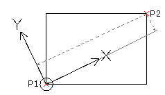
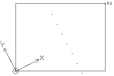
Result:
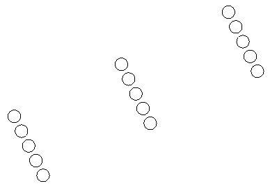
 You can use the Undo option to cancel the most recent copy operation.
 - To finish duplicating entities, press Enter.
To create random copies at a specified distance:
- Do one of the following:
- On the ribbon, click XtraTools > Modify > Copy Multiple.
- On the menu, click XtraTools > Modify > Copy Multiple.
- Type CopyMultiple.
- In the graphics area, specify the entities to copy.
- Press Enter.
- Specify the base point.
- Type Random and press Enter.
- Specify the minimum distance between copies.
- Press Enter.
As you move the pointer in the graphics area, random copies are created.
- Press Enter.
- Specify another copy option or press Enter to conclude copying.
Access
Command: CopyMultiple
Menu: XtraTools > Modify > Copy Multiple
Ribbon: XtraTools > Modify > Copy Multiple
Offseting Selected Entities
Use the OffsetX command to create new entities by applying an offset to the selected entities.
OffsetX offers additional flexibility over the Offset command for the following options:
- Multiple: Lets you create multiple offsets, one by one, in the graphics area.
- Undo: At any moment, lets you reverse the effect of the most recent operation.
- GapType: Creates extended, filleted, or chamfered corners to fill gaps in offset polylines.
To create an offset entity through a specified point:
- Do one of the following:
- On the ribbon, click XtraTools > Modify > OffsetX.
- On the menu, click XtraTools > Modify > OffsetX.
- Type OffsetX.
- Specify the Through option.
- In the graphics area, specify the entities to offset.
- Specify a point for the new entity.
- Optionally, do one of the following:
- To reverse the previous offset without terminating the running OffsetX command, specify the Undo option.
- To create several new offsets, use Shift+Pick.
- To create a new offset and erase the source object, use Ctrl+Pick.
- Press Enter to conclude the command.
To create multiple offsets:
- Do one of the following:
- On the ribbon, click XtraTools > Modify > OffsetX.
- On the menu, click XtraTools > Modify > OffsetX.
- Type OffsetX.
- Type an offset distance between the source and target entity and press Enter.
- In the graphics area, specify the entities to offset.
- Specify the Multiple option.
- Specify the side on which you want to create the offset.
- Specify offset destination points, and then press Enter.
Access
Command: OffsetX
Menu: XtraTools > Modify > OffsetX
Ribbon: XtraTools > Modify > OffsetX
Modifying the Draw Order of Entities by Color
Use the DrawOrderByColor command to modify the draw order of the selected entities based on their color.
You can control overlapping of entities according to their color. For example, you can display boundaries in front of solid hatches.
You must define the list of color priorities where the first color on the list is in front and the last color is in the back. The overlapping of entities changes according to the defined color priorities.
Optionally, you can include blocks in your selection and sort the contained entities based on their color.
 DrawOrderByColor does not affect external references.
To modify the draw order of entities by color:
- Do one of the following:
- On the ribbon, click XtraTools > Modify > Draw Order By Color.
- On the menu, click XtraTools > Modify > Draw Order By Color.
- Type DrawOrderByColor.
- In the graphics area, specify the entities.
- Press Enter.
- In the dialog box, set the color priorities using the following buttons:
- Move Top. Moves the selected color on the first position in the color list.
- Move Up. Moves the selected color higher in the color list.
- Move Down. Moves the selected color lower in the color list.
- Move Bottom. Moves the selected color on the last position in the color list.
- In the dialog box, set options:
- Modify blocks. Sorts the entities contained in block instances based on their color.
- Modify only the entities with assigned color. Sorts only the entities that have a specific color asigned. For example, entities with ByLayer or ByBlock are ignored.
- In Re-ordering method, select the sorting method:
- Draw order. Sorts the entities using the DisplayOrder command.
-
Handles. Sorts the entites physically in the drawing database. Creates entity copies and places them above the others.
 When Handles is enabled, some entities, such as hatches or groups, can lose their associative property. The sorting direction is always Front.
- In Draw order location, specify the sorting direction:
- Front. Sorts the entities by colors in front-to-back order and brings to front entities that are not specified in the color list.
- Back. Sorts the entities by colors in front-to-back order and sends behind entities that are not specified in the color list.
- Click OK.
Example:
| Initial situation | Priorities | Result |
|---|---|---|
 |
In the dialog box, specify the following color priorities and select Front.
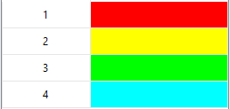
|
 |
Access
Command: DrawOrderByColor
Menu: XtraTools > Modify > Draw Order By Color
Ribbon: XtraTools > Modify > Draw Order By Color
View Tools
This section discusses:
Aligning Views in Viewports
Use the AlignViewportViews to align the views from one or more viewports to one master viewport to look like one single viewport.
 Note: This command is available in Sheet mode only.
To align the views in the viewports:
- Do one of the following:
- On the ribbon, click XtraTools > View > Align Viewport Views.
- On the menu, click XtraTools > View > Align Viewport Views.
- Type AlignViewportViews.
- Specify the master viewport.
- Specify the viewports to align with the master viewport.
Example:
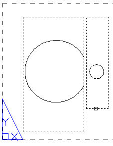
In this example, two viewports must be aligned.
Select the master viewport and the viewport to align.
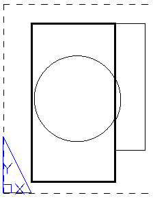
The viewports are aligned to look like one single viewport.
Access
Command: AlignViewportViews
Menu: XtraTools > View > Align Viewport Views
Ribbon: XtraTools > View > Align Viewport Views
Aligning Workspaces
Use the AlignWorkspaces command to adjust the zoom factor and position of the current view, based on the alignment points specified in the Model workspace and Sheet workspace. The tool alignes the points specified in the Model workspace with the points specified in the Sheet workspace.
 Note: This command is available in Sheet mode only.
Additionally, you can use the command for the following operations:
- Position a view correctly within a viewport, based on one point specified in Model workspace and one point in Sheet workspace. The zoom factor of the viewport does not change.
 To specify only one point in Model workspace or in Sheet workspace, press Enter at the second point prompt.
 - Zoom a view based on two points specified in Model workspace and two points in Sheet workspace. The zoom factor and the custom coordinate system (CCS) are adjusted according to the specified points.
To align workspaces:
- Do one of the following:
- On the ribbon, click XtraTools > View > Align Workspaces.
- On the menu, click XtraTools > View > Align Workspaces.
- Type AlignWorkspaces.
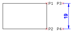
- In Model workspace, specify two points (P1 and P2) to align.
- In Sheet workspace, specify two points (P3 and P4) to align with.
- Press Enter.
The content from the Model workspace is aligned with Sheet workspace.

Access
Command: AlignWorkspaces
Menu: XtraTools > View > Align Workspaces
Ribbon: XtraTools > View > Align Workspaces
Displaying the Viewport Scale Ratio
Use the ViewportScaleRatio command to display the scale of the specified viewport on a layout Sheet.
The format of the scale ratio is according to the selected units type.
 Note: This command is available in Sheet mode only.
To display the scale ratio of a viewport:
- Do one of the following:
- On the ribbon, click XtraTools > View > Viewport Scale Ratio.
- On the menu, click XtraTools > View > Viewport Scale Ratio.
- Type ViewportScaleRatio.
- In Sheet workspace, specify the viewport.
The command window displays the scale ratio.
Examples
- Architectural: PS:MS == 1:1.45 Viewport Scale: 1′ = 1′-0″
- Engineering: PS:MS == 1:1.45 Viewport Scale: 1″ = 1.00″
- Decimal: PS:MS == 1:1.45
Access
Command: ViewportScaleRatio
Menu: XtraTools > View > Viewport Scale Ratio
Ribbon: XtraTools > View > Viewport Scale Ratio
Utilities
This section discusses:
- Creating Additional LineStyles
- Defining a Shape
- Using the Lisp Explorer
- Exporting the Current Settings
- Appending Variables to a Script File
- Exporting Variables to a Script File
- Merging Sheets
- Setting a Backup Folder for Drawing Files
Creating Additional LineStyles
Use the MakeLineStyle command to create a new LineStyle from the specified entities in drawing.
You can use points, text, shapes, lines and polylines to define the pattern for the new LineStyle.
To create a new LineStyle:
- Draw the entities defining the pattern of the LineStyle.
- Do one of the following:
- On the ribbon, click XtraTools > Utilities > Make LineStyle.
- On the menu, click XtraTools > Utilities > Make LineStyle.
- Type MakeLineStyle.
- In the dialog box, click Browse.
- Select a LineStyle file (.lin) and click Save.
The new LineStyle is stored in the selected file.
- In Name, type the name of the new LineStyle.
- In Description, type a short text describing the new LineStyle.
 Note: If Description is empty, the command creates an automatic description.
 - Click OK.
- In the graphics area, specify the segment that will be repeating throughout the LineStyle:
- A point to start the line definition.
- A point to end the line definition.

- In the graphics area, select lines, polylines, points, shapes, or text objects for the line style pattern and press Enter.
The new LineStyle is created. You can use it immediately.
Access
Command: MakeLineStyle
Menu: XtraTools > Utilities > Make LineStyle
Ribbon: XtraTools > Utilities > Make LineStyle
Defining a Shape
Use the MakeShape command to define a Shape based on specified entities. You can use lines, polylines, points, shapes, or text objects for the Shape definition.
 To include a point in a Shape, draw a very short line segment and use a higher enough resolution for the Shape definition to display the segment as a point. If the short segment does not appear in the Shape, use a higher resolution.
To define a shape:
- Draw the entities of the Shape (lines, polylines, points, shapes, or text objects).
- Do one of the following:
- On the ribbon, click XtraTools > Utilities > Make Shape.
- On the menu, click XtraTools > Utilities > Make Shape.
- Type MakeShape.
- In the dialog box, specify the following:
- In File, type the name of the file that will store the Shape.
- In Name, type the name of the Shape.
- In Resolution value, specify the quality of the grid for Shape recalculation.
- Click OK.
- In the graphics area, specify the base point.
- In the graphics area, specify the entities for the Shape (lines, polylines, points, shapes, or text objects).
- Press Enter.
 You can insert shapes using the InsertShape command.
Access
Command: MakeShape
Menu: XtraTools > Utilities > Make Shape
Ribbon: XtraTools > Utilities > Make Shape
Using the Lisp Explorer
Use the LispExplorer to display information about Lisp commands, variables, and functions defined in the application.
The LispExplorer allows the following:
- Display a list of available Lisp functions
- Display the code of a Lisp function
- Load Lisp files in the application
- Search for a text inside the code
- Display Lisp commands, functions and variables defined in the application
- Export the list of Lisp commands, functions and variables defined in the application
 ListExplorer does not display the code of encrypted Lisp functions.
To display the code of a Lisp function
- Do one of the following:
- On the ribbon, click XtraTools > Utilities > Lisp Explorer.
- On the menu, click XtraTools > Utilities > Lisp Explorer.
- Type LispExplorer.
- In the dialog box, in Location, select Library.
- Click Browse.
- Select the folder containing the Lisp files and click Specify folder. The Files section displays the list of Lisp files in the selected folder.
- In Files, click the file name. The Functions section displays the functions contained in the selected file.
- Click a function to display its source code.
- Optionally, use the Display as option to control how the function will be displayed.
- Header Only: Displays only the function header
- Function Only: Displays only the function code
- Both: Displays the function header and the code
- Use Search to search for a text inside the displayed function.
To load a Lisp file:
- Do one of the following:
- On the ribbon, click XtraTools > Utilities > Lisp Explorer.
- On the menu, click XtraTools > Utilities > Lisp Explorer.
- Type LispExplorer.
- In the dialog box, in Location, select Library.
- Click in Browse.
- Select the folder containing the Lisp files and click Specify folder. The Files section displays the list of Lisp files in the selected folder.
- In Files, click the Lisp file name.
- Click Load.
To display Lisp commands, functions and variables defined in the application:
- Do one of the following:
- On the ribbon, click XtraTools > Utilities > Lisp Explorer.
- On the menu, click XtraTools > Utilities > Lisp Explorer.
- Type LispExplorer.
- In the dialog box, in Location, select Loaded.
- In Type, select Commands, Functions or Variables.
 Click a column name in the title bar to sort the list alphabetically.
 - Optionally, you can export the list to a .dmp file. To export:
- Click Export.
- In the dialog box, specify the file where to store the file and click Save.
Access
Command: LispExplorer
Menu: XtraTools > Utilities > LispExplorer
Ribbon: XtraTools > Utilities > LispExplorer
Exporting Current Settings
Use the ExportSettings command to export current settings to an external file. For example, use the export file to report an error that occured when using XtraTools.
The file provides the following information:
- General user information, such as user name and contact information
- Steps necessary to reproduce the error
- Information about your computer configuration.
To export curent settings:
- Do one of the following:
- On the ribbon, click XtraTools > Utilities > Export Settings.
- On the menu, click XtraTools > Utilities > Export Settings.
- Type ExportSettings.
- In the dialog box, enter the following information:
- Name, email address, and phone number.
- In Issue description, type a short description of the error.
- In Steps to reproduce the issue, describe the steps necessary to reproduce the error.
 System information displays information about your computer configuration.
- Click OK.
The command generates a file that you can send to report the error.
Access
Command: ExportSettings
Menu: XtraTools > Utilities > Export Settings
Ribbon: XtraTools > Utilities > Export Settings
Exporting Variables to a Script File
Use the ExportVariables command to export the system variable values to a script file (.scr file). You can run the script file later, to reset variable settings. See Writing and Running Script Files.
To export the system variable:
- Do one of the following:
- On the ribbon, click XtraTools > Utilities > Export Variables.
- On the menu, click XtraTools > Utilities > Export Variables.
- Type ExportVariables.
- In the dialog box, in Variable type, select the category of system variables to export:
- Read-only: Read-only variables.
- Dangerous: Variables that can affect the software functionality.
- Standard: Common variables that can be modified without changing the normal software functionality.
 Selecting All, exports all variables.
 - Click Export to script.
- In the dialog box, specify the file in which to store the settings.
- Click Save.
- Click Close.
Access
Command: ExportVariables
Menu: XtraTools > Utilities > Export Variables
Ribbon: XtraTools > Utilities > Export Variables
Appending Variables to a Script File
Use the VariableToScript command to append selected system variables to an existing script file (.scr file). You can run the script file later, to reset variable settings.
To export system variables:
- Do one of the following:
- On the ribbon, click XtraTools > Utilities > Variable To Script.
- On the menu, click XtraTools > Utilities > Variable To Script.
- Type VariableToScript.
- In the dialog box, in Variable type, select the category of system variables to export:
- Read-only: Read-only variables.
- Dangerous: Variables that can affect the software functionality.
- Standard: Common variables that can be modified without changing the normal software functionality.
 Selecting All, exports all system variables.
 - Click Append to script.
- In the dialog box, select an existing file and click Open.
- Click Open.
- Click Close.
Access
Command: VariableToScript
Menu: XtraTools > Utilities > Variable To Script
Ribbon: XtraTools > Utilities > Variable To Script
Merging Sheets
Use the MergeSheets command to merge several layout sheets into one sheet.
You can display the merged Sheets on an existing Sheet or on a new Sheet. Optionally, you can remove the unused Sheets.
To merge several sheets:
- Do one of the following:
- On the ribbon, click XtraTools > Utilities > Merge Sheets.
- On the menu, click XtraTools > Utilities > Merge Sheets.
- Type MergeSheets.
- In the dialog box, in Sheets to merge, select the Sheets to merge.
- In Target sheet, specify the Sheet where you want to copy the merge sheets:
- Select an existing Sheet from the list.
– or –
- In Name, type the name of a new Sheet.
- Select an existing Sheet from the list.
- Optionally, select options:
- Delete unused sheets. Removes unused Sheets from the result.
- Delete geometry from merged sheets. Removes existing geometry from the target Sheet.
- Click OK.
Each source Sheet will have a corresponding view, represented as a rectangle, on the target Sheet.
Access
Command: MergeSheets
Menu: XtraTools > Utilities > Merge Sheets
Ribbon: XtraTools > Utilities > Merge Sheets
Setting a Backup Folder for Drawing Files
A drawing backup file is a copy of the drawing file one version older than the currently saved drawing.
You can enable automatic backup from the Options dialog box (Save backup at each save option from the System Options > Auto-save/backups).
Every time you manually save a .dwg, the software automatically creates a backup file. By default, the drawing backup file is saved in the same folder as the drawing (.dwg file) and has the same name as the drawing but with a .bak extension.
Use the SetBackupFolder command to specify the destination folder for drawing backup (.bak) files.
Note: There is only one backup file for a drawing. A newly created backup file replaces the existing backup file of the same name.
To set a backup folder for drawing files:
- Type SetBackupFolder.
- In the command window, type the path for the backup folder.
Access
Command: SetBackupFolder
XtraTools Commands Reference
| Command | Description | Menu |
|---|---|---|
| AlignViewportView | Aligns the views from one or more viewports to one master viewport to look like one single viewport. | XtraTools > View |
| AlignWorkspaces | Adjust the zoom factor and position of the current view, based on the alignment points specified in the Model workspace and Sheet workspace. | XtraTools > View |
| Breakline | Draws a line with a breakline symbol | XtraTools > Draw |
| ConvertSimpleNotes | Transforms one or multiple text entities to a text paragraph | XtraTools > Annotation |
| CopyMultiple | Creates multiple copies of the selected entities | XtraTools > Modify |
| CurvedText | Places a text on an arc entity | XtraTools > Annotation |
| DrawOrderByColor | Modifies the draw order of the selected entities based on their color (dialog box variant). | XtraTools > Modify |
| -DrawOrderByColor | Modifies the draw order of the selected entities based on their color (command window variant). | |
| EditTextCase | Modifies the case style of selected SimpleNote, BlockAttribute, Note or Dimension (dialog box variant). | XtraTools > Annotation |
| -EditTextCase | Modifies the case style of selected SimpleNote, BlockAttribute, Note or Dimension (command window variant). | |
| EditTextJustification | Modifies the justification point of selected text, paragraph or attribute entities | XtraTools > Annotation |
| EditTextOrientation | Rotates selected text, paragraph or attribute entities keeping their current position | XtraTools > Annotation |
| ExportDimensionStyle | Exports the dimension styles from the current drawing to an external ASCII file | XtraTools > Dimensions |
| ExplodeText | Converts annotations into Polylines, which represent the text outline | XtraTools > Annotations |
| ExportSettings | Exports the current settings to an external file | XtraTools > Utilities |
| ExportVariables | Exports the system variable values to a script file (.scr file). | XtraTools > Utilities |
| FitText | Resizes the width of a text entity to fit between two selected points | XtraTools > Annotation |
| GetBlockInfo | Counts the block insertions in drawing and displays the result | XtraTools > Block |
| GetNestedProperties | Displays the properties of an entity of a Block or a Reference (dialog box variant) | XtraTools > Block |
| -GetNestedProperties | Displays the properties of an entity of a Block or a Reference (command window variant). | |
| ImportBlockAttributes | Imports BlockAttribute values previously exported to an ASCII file | XtraTools > Block |
| ImportDimensionStyle | Imports dimension styles and their settings from an ASCII file (with .dim extension) | XtraTools > Dimensions |
| LispExplorer | Displays information about commands, variables and Lisp functions defined in the application | XtraTools > Utilities |
| MakeLineStyle | Creates a new LineStyle from the specified entities in drawing | XtraTools > Utilities |
| MakeShape | Defines a Shape based on specified entities | XtraTools > Utilities |
| MergeSheets | Merges several Sheets into a single Sheet (dialog box variant). | XtraTools > Utilities |
| -MergeSheets | Merges several Sheets into a single Sheet (command window variant). | XtraTools > Utilities |
| NumberText | Inserts sequential numbering to selected text entities | XtraTools > Annotation |
| OffsetX | Creates new entities by applying an offset to the selected entities | XtraTools > Modify |
| PatternHatch | Creates hatches using Block entities, images, References or masks | XtraTools > Draw |
| RedefineBlockAttribute | Redefines the shape of a Block keeping its original BlockAttribute values | XtraTools > Block |
| RedefineBlockAttributeValues | Globally modifies the values of the BlockAttributes of all instances of the selected blocks | XtraTools > Block |
| ReplaceBlock | Replaces Block insertions by other Blocks (dialog box variant) | XtraTools > Block |
| -ReplaceBlock | Replaces Block insertions by other Blocks (command window variant) | – |
| ReplaceBlockByReference | Replaces Block insertions by instances of an external Reference (dialog box variant) | XtraTools > Block |
| -ReplaceBlockByReference | Replaces Block insertions by instances of an external Reference (command window variant) | – |
| ScaleBlock | Scales Blocks relative to their insertion point | XtraTools > Block |
| SetBackupFolder | Specifies the destination folder for drawing backup (.bak) files | – |
| TextFrame | Creates a frame around specified text entities | XtraTools > Annotation |
| TextMask | Places a blank area behind specified text entities | XtraTools > Annotation |
| TextUnMask | Removes the masks assigned to selected text entities | XtraTools > Annotation |
| VariableToScript | Appends selected variables to an existing script file (.scr file) | XtraTools > Utilities |
| ViewportScaleRatio | Displays the scale of the specified viewport on a layout Sheet. | XtraTools > View |

