
Introduction
FLUIDDESK BIM
Building Information Modeling (BIM) is a workflow that lets you create and manage 3D model information during the lifecycle of a project.
The following file types are supported:
- .ifc files
- .rvt files
- .rva files
You can import BIM files, such as .ifc and .rvt files to your project and create the necessary documentation based on the BIM model. Various CAD features let you access information about the model and annotate the drawings.
The BIM Navigator palette groups all tools necessary for working with BIM models and drawings.
The basic workflow for working with BIM models includes the following steps:
-
Import the BIM file containing the model.
You can import .ifc, .rvt, and .rva files to your project and load the BIM model in the current .dwg file. The current .dwg file stores a link to the imported BIM file. See Importing BIM Files.
-
Work with the BIM model in the graphics area.
Once you have loaded the BIM model in the graphics area, you can do the following.
- Display BIM entities properties in the Properties palette.
- Move the BIM file if required.
- Use filters to control the display of BIM entities in the graphic area based on criteria, such as: Category, Predefined Type, or Entity Type.
- Map BIM material names that exist in the loaded BIM file to the materials available in the BIM Materials Styles Library.
-
Extract data from BIM entities to .csv files.
You can extract information from a set of entities using the Data Extraction wizard. See Extracting Data to Tables and Files.
-
Specify where to cut the model to create drawings. See Creating BIM Drawings.
- Annotate the drawings using annotation tools.
- Use hatches and line weights to improve the display of entities in the drawings.
 As the project evolves, new versions of BIM models may be received. Reload the BIM file to update the software with the current version of the BIM model. You must refresh the drawings so that all of the drawings reflect the current state of the BIM. See Managing BIM Drawings.
 -
Place the drawings on the sheets.
When you place a drawing on a sheet, the software automatically places drawing callout symbol and drawing title under the drawing. See Placing Drawings on Sheets.
Before placing drawings on a sheet, open a sheet tab and set the sheet size options.
This chapter discusses:
- Importing BIM Files
- Managing BIM Files
- Working with BIM Models
- Working with BIM Drawings
- Working with BIM Materials
- Using the BIM Navigator
Importing BIM Files
FLUIDDESK BIM
You can import .ifc and .rvt files and display their content in the current .dwg file. The current .dwg file stores a link to the imported BIM Files.
Note: Make sure to save the drawing file before importing .ifc and .rvt files.
To import a BIM file:
- Do one of the following:
- In the BIM Navigator palette, click Import.
- Type BIMImport.
- Navigate to the file to import and click Open.
The BIM Navigator displays the imported file in the BIM Files list.
Click  to insert the BIM file content in the graphics area.
Access
BIM Navigator palette: click Import.
Managing BIM Files
FLUIDDESK BIM
The BIM Files category of the BIM navigator palette provides tools for managing BIM files that you imported into the drawing.
These file types are listed in the tree view:
- .ifc files
- .rvt files
You can:
- Import BIM files.
When importing BIM files, the curent drawing stores a link to the imported BIM file.
- Control the access to a BIM file.
You can lock a BIM file to prevent it from editing. Unlocking the BIM file displays the file content in the graphics area. Additionally, the Entities category lists the BIM entities in a tree view.
- Control the visibility of the entities.
You can show or hide all entities of the BIM files that you imported in the current drawing.
- Manage the link with the BIM file.
When working on a project, you might need to update some BIM files. You must reload the BIM file to display its content in the form in which it was most recently saved.
To unlock a BIM file:
- In the BIM Navigator palette, click BIM Files.
- Select the file to load in the graphics area and click Unlock.
The BIM entities are displayed in the graphics area.
Note: To lock the BIM file, click Lock.
To unload a BIM file:
- In the BIM Navigator palette, select BIM Files.
- In the imported files list, right-click the file to unload and click Unload.
The content of the selected file is no longer visible in the graphics area, but the link to the file is maintained. To redisplay an unloaded BIM file, specify the Reload from option.
To reload a BIM file:
When working on a project, you might need to update some BIM files. You must reload the BIM file to display its content in the form in which it was most recently saved.
- In the BIM Navigator palette, select BIM Files.
- In the imported files list, right-click the file to reload and click Reload.
The content from the BIM file is displayed in its latest state.
To reset the path to a BIM file:
- In the BIM Navigator palette, select BIM Files.
- In the imported files list, right-click the file to reload and click Reload from.
- Navigate to the new location and select the BIM file, then click Open.
To delete a BIM file:
- In the BIM Navigator palette, select BIM Files.
- In the imported files list, right-click the file to delete and select Delete from the context menu.
The file is deleted from the imported files list. The content of the selected file is no longer visible in the graphics area.
Access
Command: BIMNavigator
Ribbon: BIM > Palettes > Navigator
Working with BIM Models
FLUIDDESK BIM
You can import BIM files, such as .ifc and .rvt files to your project and load the BIM model in the graphics area.
This section discusses:
- Viewing BIM Entities Properties
- Moving BIM Files
- Filtering BIM Entities
- Controlling the BIM Entities Display
Viewing BIM Entities Properties
FLUIDDESK BIM
Use the Properties palette to view the parameters that define the properties of BIM entities.
When you select other categories of entities and BIM entities, you can use the filter drop-down list to view only the properties for a specific category. For BIM entities, the filter drop-down displays BIM Entity.
To view BIM entities properties:
- Do one of the following:
- On the menu, click Modify > Properties.
- On the ribbon, click BIM > Palettes > Properties.
- Type Properties.
- In the graphics area, select one or more entities of the BIM model.
The Properties palette displays the BIM entity properties in read-only mode.
Access
Command: Properties
Moving the BIM File Content
FLUIDDESK BIM
Use the BIMMove command to reposition all entities of the BIM file within the coordinate system without changing their orientation or size.
To move BIM file content:
- Type BIMMove at the command prompt.
- In the graphics area, specify one or more BIM entities and press Enter to complete your selection.
- Specify a base point and target point to move the BIM entities by the specified amount.
The BIM entities moves as specified.
Access
Command: BIMMove
Filtering BIM Entities
FLUIDDESK BIM
You can use filters to control the display of BIM entities in the graphic area and in the Entities tree view, based on criteria, such as: Building, Name, Predefined Type, or Entity Type.
The Filter category of the BIM Navigator lets you define and manage filters.
A filter defines rules based on categories and properties.
You can:
- Create complex selection filters, using relational operators.
- Apply selection filters transparently during the execution of modification commands.
- Save and apply named filters
After you select BIM entities based on the filter, you can move the entities using the BIMMove command.
Note: The filter does not create a selection set. It defines criteria to apply on a selection set.
To create and apply selection filters:
- On the BIM Navigator palette, click Filters.
- In Entities, under Criteria, do the following settings:
- Specify a property.
- Specify a relational operator (== or !=).
- Specify a value.
- Click Add
 to add the item to the criteria list.
You can delete criteria.
- Repeat steps 2 and 3 as needed.
- In Group by, select one or more criteria if needed. Click Add to add the item to the list.
To delete a criteria, click
 .
. - In Sort, specify the property according to which to filter the BIM entities.
- Select an ascending or a descending order.
- Do one of the following:
- To save the filter under the same name: click Save.
- To save the filter under a different name: click Save As.
- In the Name Filter dialog box, specify the name and click OK.
The filter is now active.
Note: The Filter drop-down list displays all available filters.
To modify a filter criteria:
- On the BIM Navigator palette, click Filters.
- From the drop-down list, specify the filter to modify.
- In Entities, use options as needed:
- Add or delete criteria
- Add or delete grouping criteria
- Change the order
- Do one of the following:
- To save the filter under the same name: click Save.
- To save the filter under a different name: click Save As.
To delete a filter:
- On the BIM Navigator palette, click Filters.
- From the drop-down list, specify the filter.
- Click
 and specify Delete from the context menu.
To rename a filter:
- On the BIM Navigator palette, click Filters.
- From the drop-down list, specify the filter.
- Click and specify Rename from the context menu.
Controlling the BIM Entities Display
FLUIDDESK BIM
The Entities category displays the entities of each imported BIM file in a tree view grouped according to their category and type. All categories of named entities contained in the BIM file are taken into account.
Note: The Entities category displays only after you unlock the BIM file.
The tree view lets you browse the BIM file entities. Clicking an entity or a category of entities in the tree view selects the entities in the graphics area. Additionally, double-clicking a file in the tree view selects all entities of the file in the graphics area.
To display the categories in the BIM file tree view, click the ( ) sign in front of a BIM file.
You can show or hide entities and categories of entities individually or according to a category.
You can:
- Display or hide one entity
- Display or hide certain entities
- Display or hide entities of one file
- Display or hide a category of entities
- Display or hide entities of a floor
To expand or collapse all categories:
- On the BIM Navigator palette, click Entities.
- Do one of the following:
- Click Expand
 to expand all categories from all imported BIM files.
 - Click Colapse
 to colapse all categories from all imported BIM files.
- Click Expand
To show or hide all entities:
- On the BIM Navigator palette, click Entities.
- Click
 to show or hide all entities from all imported BIM files in the graphics area.
You can also show these categories in the BIM file tree view by clicking the sign () sign in front of a BIM file (which expands the categories list).
To show or hide the entities of a category:
- On the BIM Navigator palette, click Entities.
- In the tree view, click the icon in the corresponding Show cell.
A green dot
 means show. A gray dot
 means hide.
Working with BIM Drawings
FLUIDDESK BIM
You can create plans, sections, and elevations from the BIM model:
This section discusses:
- Creating BIM Drawings
- Adding Grid Lines
- Defining Levels
- Managing BIM Drawings
- Splitting a BIM Drawing Across Multiple Sheets
- Placing Drawings on Sheets
- Publishing BIM Drawings to PDF
- Annotating BIM Drawings
- Dimensionig BIM Drawings
Creating Drawings from the BIM Model
FLUIDDESK BIM
Use the BIMSection command to automatically create the following drawings from the BIM model:
- Plans
- Sections
- Elevations
- Details
Each drawing type has a specific graphical display and appears in a different branch in the BIM Navigator.
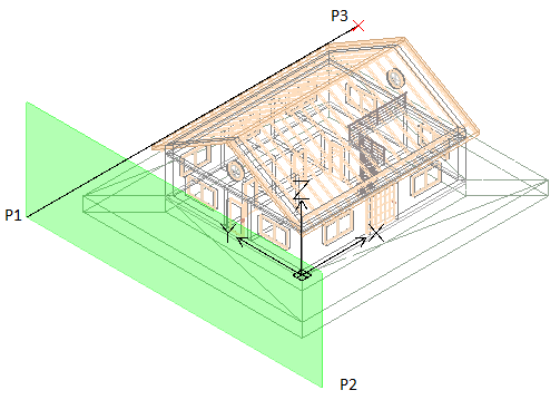
All drawing types are defined by a drawing volume clipping box which is specified by two points defining the drawing’s cutting plane, and a third point defining the drawing’s viewing direction and volume depth. BIM entities that are not within, or overlapping, the drawing volume clipping box are excluded from the drawing.
Notes:
- Each drawing created from the same BIM model is stored in a separate .dwg file.
- If the BIM model contains multiple buildings, each building will have its set of drawings. You can specify a building using its name or its index number.
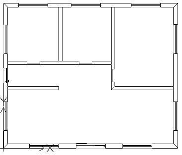
Plans
A plan drawing represents a horizontal slice through the BIM model. You can create floor plans.
You use a horizontal cutting plane to define a clipping box within the BIM model. Specify a depth to display entities of the BIM model below the cutting plane.
The BIM Navigator groups the plans in the Plans branch of the Drawings category in the BIM Navigator.
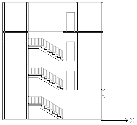
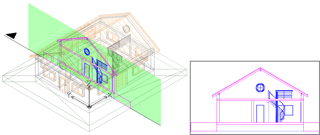
Sections
A section drawing represents a vertical slice through the BIM model.
The BIM Navigator groups the sections in the Sections branch.
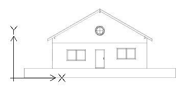
Elevations
Elevation drawings represent a vertical view of a building. Unlike Sections, Elevation drawings do not slice through the building. Rather they represent views of the BIM from the outside from different directions. You can create north, south, east, and west elevation drawings.
The BIM Navigator groups the elevations in the Elevations branch of the drawings list in the Drawings category.
Details
Detail drawings are larger scale drawings that provide a detailed representation of a specified part of a drawing.
You can create details based on a parent BIM drawing, such as a BIM section, elevation, and plan view. The detail view appears as a callout with a tag on the parent drawing. Once you draw the detail boundary in a BIM drawing, the application generates a detail drawing.
You can create a detail as a drawing or as a callout.
The BIM Navigator groups the details in the Details branch of the drawings list in the Drawings category.
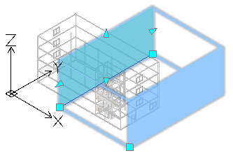
Working with the Clipping Box
The BIMSection command creates a clipping box with a specified width and depth. The first two points define the cutting plane position and the clipping box width, while the third point defines the drawing’s view direction and depth into the viewing direction. The software calculates the height from the extents of the BIM geometry.
At any time, you can resize the clipping box to include a specific part of the BIM model or change the position of the cutting plane using grip points on the drawing clipping box.
Note: Refresh the corresponding drawing after modifying the size of the clipping box or the cutting plane position.
If you delete the clipping box, the corresponding BIM drawing is also deleted. Also, if you delete a BIM drawing, the corresponding clipping box is also deleted.
You can control the clipping box display.
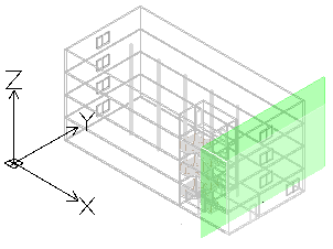
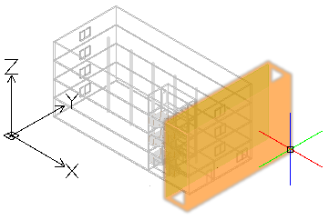
To display the clipping box:
- In the BIM Navigator, in Drawings, select a drawing.
- At the bottom of the palette, select Show Clipping Box.
Hovering over the cutting plane (the green plane in the BIM Model) displays the entire clipping box.
Controlling the Representation of BIM Entities in Drawings
When you create a drawing based on a BIM model, the software automatically generates a set of specific layers on which the entities are placed according to their location within the drawings clipping box relative to the cutting plane. Each layer name includes the drawing name as layer name prefix, which lets you identify the layers of a drawing.
Each BIM drawing has a flatshot cut and a flatshot forward layer:
- Flatshot cut. Contains a flatshot representation of BIM entities that cross the drawings cutting plane.
- Flatshot forward. Contains BIM entities that are beyond the cutting plane, in forward direction.
You can use the Layers Manager to specify different representations of BIM entities depending on the BIM entity location within the drawings clipping box relative to the cutting plane. Additionally, for any BIM entity from the drawing, the Properties palette lets you change the hatch.
Example:
| Flatshot cut |  |
| Flatshot forward |  |
To create a plan from a BIM model:
- In the graphics area, set up a suitable 2D view. Use the Views command.
For example, display the plan view of a floor.
- Do one of the following:
- On the ribbon, click BIM > Drawings > Plan.
- Type BIMSection and specify the Plan option.
- In the command window, specify the name of the plan and press Enter.
The plan appears in the BIM Navigator, in the Plans branch.
Note: Clicking Isolated
to the right of the drawing in the drawing list in BIM Navigator displays the drawing in the graphics area. Clicking the button a second time hides the drawing and returns to the 3D model view.
To create a section from a BIM model:
Before creating drawings, make sure you are working with the latest BIM model. Use the Reload from option to reload the latest BIM file from its location.
- In the graphics area, set up a suitable 3D view. Use the Views command.
- Do one of the following:
- On the ribbon, click BIM > Drawings > Section.
- Type BIMSection and specify the Section option.
A cutting plane is attached to the pointer.
Note: The cutting plane is perpendicular to the section line.
- In the graphics area, move the cutting plane preview to the desired location and click to specify the start point of the section line (P1).
- Specify the second point of the section line (P2).
- Specify a point or a value for the clipping box depth (P3).
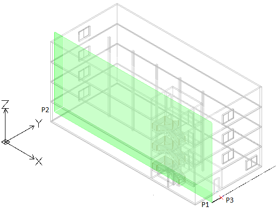
- In the command window, specify the name of the section and press Enter.
The section appears in the BIM Navigator, in the Section branch.
Note: Clicking Isolated
to the right of the drawing in the drawing list in BIM Navigator displays the drawing in the graphics area. Clicking the button a second time hides the drawing and returns to the 3D model view.
To create an elevation from a BIM model:
- In the graphics area, set up a suitable 3D view. Use the Views command.
- Do one of the following:
- On the ribbon, click BIM > Drawings > Elevation.
- Type BIMSection and specify the Elevation option.
A cutting plane is attached to the pointer.
- In the graphics area, move the cutting plane preview to the desired location and click to specify the start point of the elevation line (P1).
- Specify the second point of the elevation line (P2).
- Specify a point or a value for the clipping box width (P3).
- In the command window, specify the name of the elevation and press Enter.
The elevation appears in the BIM Navigator, in the Elevation branch.
To create a drawing from a building:
- In the graphics area, set up a suitable view. Use the Views command.
- Do one of the following:
- On the ribbon, on the BIM > Drawings panel, select the suitable tool for creating drawings.
- Type BIMSection and specify the suitable option: Plan, Section, or Elevation.
- Specify the Building option
- To specify the building for which to create the drawings, do one of the following:
- Specify the Building index option and press Enter. Type the index number corresponding to the building for which to create drawings or specify the ? option to list existing buildings.
- Specify the building name and press Enter.
The graphics area displays the specified building.
- Perform the steps corresponding to the selected tool for drawing creation.
The drawing appears in the BIM Navigator, in the corresponding branch of the specified building. The building name appears on the drawing.
Adding Grid Lines
FLUIDDESK BIM
Grids are auxiliary elements that are useful for placing structural elements, such as columns and walls, in a BIM project.
Grids consist of series of labeled lines. Each grid line consists of the following elements:
- Central line
- Start line
- End line
- Symbols (bubbles)
Use the BIMGridLines command to add grid lines to a BIM drawing.
You can create:
- Vertical grid lines
- Horizontal grid lines
The command automatically numbers each grid line. You can use letters and numbers for labeling grid lines. By default, vertical grid line labels are letters, while horizontal grid line labels are numbers. The numbering starts from the last horizontal, respectively vertical grid line.
Note: Adding grid lines using the Copy command duplicates the grid line without adjusting the numbering.
To add grid lines to a BIM drawing:
Note: You can add grid lines only in horizontal sections.
- Do one of the following:
- On the ribbon, click BIM > Annotate > BIM Grid Lines.
- On the menu, click BIM > Grid Lines.
- Type BIMGridLines.
- In the graphics area, do the following:
- Move the cursor horizontally and specify the points where you want to place vertical grid lines.
Vertical grid lines are automatically alphabetically labeled. The labeling starts from the last vertical grid line label.
- Press Enter to change the grid line direction.
- Move the cursor vertically and specify the points where you want to place horizontal grid lines.
Horizontal grid lines are automatically numbered. The numbering starts from the last horizontal grid line.
- Move the cursor horizontally and specify the points where you want to place vertical grid lines.
- Press Enter.
Customizing Grid Lines
Using the Properties palette you can change the appearance of the grid lines.
You can do the following:
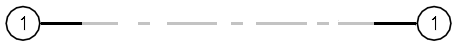
- Hide segments of the grid line. For example, the central segment
- Show or hide grid symbols at grid lines
- Offset grid symbols
- Change the line color, weight, and type. For example, you can use a different color to represent the central segment.
Examples:
Grid line with gap. Only the end segments are visible.
Grid line with a different line color
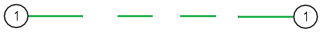
Central segment with a different color and type
To show or hide grid symbols:
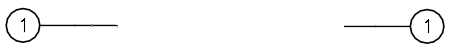
By default, grid symbols appear at both ends of a grid line.
- In the graphics area, specify a grid line.
- In the Properties palette, in Visibility, specify Yes or No to show or hide the desired grid symbol:
- Start Symbol
- End Symbol
The specified grid line will have symbols at one end.
Adjusting Grid Lines and Symbols Position
Use the middle grip point to move a grid line. In case of overlapping grid symbols, grip points let you offset the bubbles.
To offset a grid symbol:
- In the graphics area, specify a grid line.
The grid line is selected and the grip points are displayed.
- Click and drag the grip point near the grid symbol to move the symbol to the desired location.
Defining Levels
FLUIDDESK BIM
Use the BIMLevels command to define levels in vertical views, such as elevations and sections.
In BIM drawings, levels are auxiliary elements that indicate the altitude of floors, foundations, and the roof of buildings.
Example:

Levels consist of the following elements:
- Central segment
- Start segment
- End segment
- Symbols (bubbles)
To define a level:
Note: You can add levels only in elevations and vertical sections.
- Do one of the following:
- On the ribbon, click BIM > Annotate > Levels.
- On the menu, click BIM > Levels.
- Type BIMLevels.
- In the graphics area, specify the first level point.
- Move the cursor horizontally and specify the second level point.
- In the command window, type the name of the level and press Enter.
- Repeat steps 2 to 4 as needed to define other levels.
Customizing Levels
Using the Properties palette you can change the appearance of the levels.
You can do the following:
- Hide segments of the level line. For example, the central segment.
- Show or hide level symbols
- Change the line color, weight, and type. For example, you can use a different color to represent the central segment.
Additionally, you can adjust the position of the level symbols using grip points. In case of overlapping level symbols, grip points let you offset the bubbles.
To show or hide level symbols:
By default, level symbols appear at both ends of a level line.
- In the graphics area, specify a level.
- In the Properties palette, in Visibility, specify Yes or No to show or hide the desired level symbol:
- Symbol #1
- Symbol #2
To move levels:
- In an elevation or vertical section, select the level to move.
- Click and drag the level to the new position.
To offset a level line from its symbol:
- In an elevation or vertical section, specify the level to modify.
The level is selected and the grip points are displayed.
- Click and drag the grip point near the level symbol to move the symbol to the desired location.

Managing BIM Drawings
FLUIDDESK BIM
The Drawings category of the BIM Navigator palette provides tools for working with drawings that you created from the BIM models imported into your project.
Note: The Drawings category appears only after you create at least one drawing.
Displaying Drawings
You can display each drawing in the graphics area, in the Model workspace.
To improve the drawing display, use hatches, various line colors and styles:
- Select drawing entities according to suitable criteria and specify the hatch in the Properties palette.
To display a drawing in the graphics area:
- On the BIM Navigator palette, click Drawings.
- In the drawing list, right-click the drawing to display and select Open from the context menu.
The drawing is displayed in a new drawing tab.
Alternatively, you can double-click the drawing to display. -
Note: All CAD entities from the drawing retain their BIM properties.
Refreshing Drawings
As the project evolves, various changes might be done within the BIM model. As the existing drawings may not reflect the changes, you must update them.
The update is required in the following situations:
- After reloading the BIM file to display its content in the form in which it was most recently saved.
- After modifying a drawing’s clipping box using grip points.
Before updating the drawings, reload the BIM file to display its content in the form in which it was most recently saved.
You can refresh each drawing individually or all drawings at once.
To refresh a BIM file:
- In the BIM Navigator palette, in BIM Files, right click a BIM file and select Reload from.
To refresh a drawing:
- In the BIM Navigator palette, in Drawings, do one of the following:
- Right-click a drawing and select Reload from from the context menu.
- Select a drawing and click Refresh
 .
.
The drawing is updated according to the BIM model latest state.
You can use the Refresh All button to refresh all drawings.
Deleting Drawings
If you delete the clipping box, the corresponding drawing is also deleted. Also, if you delete a drawing, the corresponding clipping box is also deleted.
To delete a drawing:
- In the BIM Navigator palette, select Drawings.
- In the drawings list, right-click the drawing to delete and select Delete from the context menu.
The drawing is deleted from the drawings list. The corresponding .dwg file is moved to a temporary folder from where you can recover it, if necessary. The corresponding clipping box is removed from the graphics area.
To delete a drawing from a sheet, delete its drawing title in the graphics area.
Splitting a BIM Drawing Across Multiple Sheets
FLUIDDESK BIM
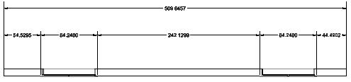
When working with larger BIM projects, sections, plans, or elevations that have been created from the BIM model might be too large to fit on a single sheet. Also, drawings can be much larger than the sheet size.
In such situations, a possible solution is to split the drawing in rectangular parts and show each part on a separate sheet, at a suitable scale. After printing, matching the printed view tiles forms the primary drawing.
The BIMSplitDrawing command lets you split a specified area of a drawing into multiple equal crop tiles.
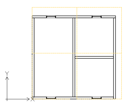
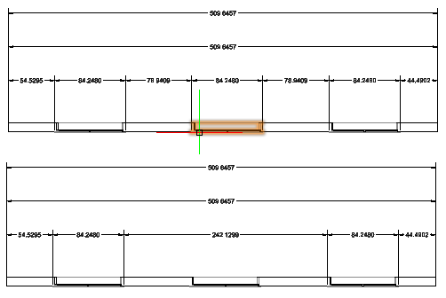
Crop tiles that you have specified in the primary view generate a set of so called dependent views. Dependent views provide exact copies of the corresponding crop tile from the primary view.
In the BIM Navigator, dependent views appear grouped under the primary view.
From the BIM Navigator, you can do the following:
- Display the crop tile for each dependent view. In the graphics area, the corresponding crop tile appears in a dashed line.
- Delete dependent views. You can delete dependent views all at once or one by one.
The basic workflow for working with BIM models includes the following steps:
-
Prepare the view that you want to split.
Add all the necessary information. Plan the size of the area to split and the size of the crop tiles. The size of the tiles should be determined based on the sheet format. For example, to print a drawing on an A3 sheet, the crop tiles should fit on A3.
-
Define the area to split.
On the primary drawing, specify two diagonal corners to define a rectangular area.
-
Define the crop tiles.
Define the crop tiles corresponding to each part of the drawing to display in the dependent view. You can split the drawing
- Based on a template (available sheet format)
- Based on defined rectangular areas
- Create the sheets on which to place the dependent views
- Place each dependent view on a separate sheet.
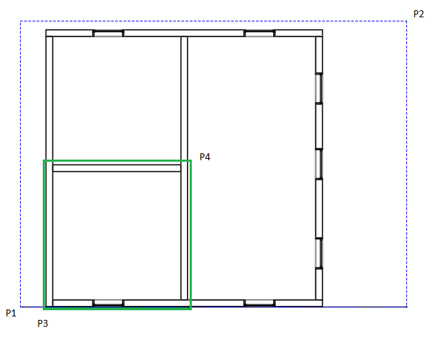
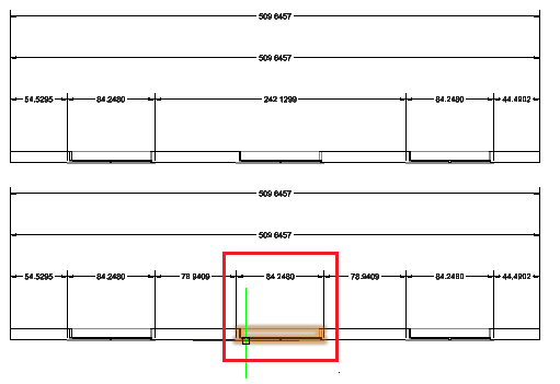
To split a BIM drawing into rectangular crop tiles:
Before starting, backup the drawing that you want to split.
- In the BIM Navigator, select the drawing to split.
Note: You cannot split a drawing that is already split. To modify the crop tiles, delete all dependent views and split the drawing again.
- Do one of the following:
- On the ribbon, click BIM > Drawing > Split Drawing.
- On the menu, click BIM >Drawing> Split Drawing.
- Type BIMSplitDrawing.
- In the graphics area, specify the first corner of the drawing area to split (P1).
- Specify the opposite corner of the drawing area to split (P2).
- Specify the first corner of the tile (P3).
- Specify the opposite corner of the tile (P4).
- Specify the point from which to start splitting the rectangular drawing area. For example, P3.
- If necessary, specify horizontal and vertical overlapping.
Access
Command: BIMSplitDrawing
Menu: BIM > Drawing > Split Drawing
Ribbon: BIM > Drawing > Split Drawing
Placing Drawings on Sheets
FLUIDDESK BIM
You can place drawings on sheets. All sheets on which you place drawings created from the BIM model are listed in the drawings list, under the Sheets branch. All drawings that you placed on the sheet appear under the corresponding sheet.
When you place a drawing on a sheet, the software automatically places drawing callout symbol and drawing title under the drawing.
Drawing Callouts
Callout symbols call other drawings that are already placed on the same or other sheets.
Also calls out drawings that have been created but have not yet been placed on any sheet.
The software automatically fills the drawing sheet and drawing number fields in drawing callout symbols.
Drawing Titles
When you place a drawing on a sheet, the software automatically places drawing title under the drawing. The drawing title contains drawing name, scale, sheet number, and drawing number. The software fills in the drawing title’s sheet number from the name of the sheet tab. You can change the drawing number in the Properties palette. After modifying the drawing number value in the drawing title, the software replicates that number in all drawing callout symbols on all sheets that call that drawing’s title.
To place a drawing on a sheet:
Note: Refresh the drawings before placing the drawing on a sheet (BIM Navigator palette: Refresh All  ).
).
- Click on the Sheet tab on which you want to place the drawing.
- On the BIM Navigator palette, in Drawings, select a drawing.
- Do one of the following:
- Click Place on Sheet
 .
. - Right-click a drawing and select Place on sheet.
The drawing frame appears attached to the mouse cursor.
- Click Place on Sheet
- Specify the Scale option.
- Type the scale value and press Enter.
- In the graphics area, specify the drawing location.
In the BIM Navigator, in Drawings, the drawing is listed under the corresponding sheet. The drawing name includes the scale as well.
You can refresh the drawings at any time (BIM Navigator palette: Refresh All ).
To delete a drawing from the sheet:
Do one of the following:
- In the graphics area, select the drawing title and press Delete.
- On the BIM Navigator palette, in Drawings, expand the Sheets branch, right-click the drawing and select Delete from the context menu.
Publishing the BIM Drawings to PDF
FLUIDDESK BIM
Use the BIMPublishToPDF command to publish a BIM drawing to the PDF format. You can save the PDF file either in the project folder, or in a specified location.
To publish a BIM drawing to PDF:
- In the BIM Navigator palette, in Drawings, specify a drawing to open.
- Do one of the following:
- On the menu, click BIM > Publish to PDF
- On the ribbon, click BIM > Publish > Publish to PDF
- Type BIMPublishToPDF
- To specify whether to use the project name and path for the PDF, type Yes or No. Press Enter.
If you specify No, the Specify file dialog box opens so you can set the location and the name for the file.
Access
Command: BIMPublishToPDF
Menu: BIM > Publish to PDF
Ribbon: BIM > Publish > Publish to PDF
Annotating BIM Drawings
FLUIDDESK BIM
You can label BIM entities in a BIM drawing in order to provide detailed information.
Use labels to identify BIM entities in a BIM drawing.
This section discusses:
About Labels
FLUIDDESK BIM
Labels are annotations that you can use to identify BIM entities in a BIM drawing.
A label consists of a block that contains one or more attributes. Labels read and display BIM properties of the labeled BIM entity.
The software provides a Label Library that contains a set of predefined labels for each category of BIM entities. Additionally, you can define your own labels using user-defined Blocks and BlockAttributes.
You can assign a default label to the following categories of BIM entities:
- Doors
- Windows
- Walls
In addition to the default labels, you can define your own labels as Blocks containing BlockAttributes. BlockAttributes let you use Fields to refer properties of BIM entities in a user-defined label.
Once you create the label, the software creates a link with the BIM entity. When the corresponding BIM entities properties are modified, labels automatically update.
Labels remain associated with the BIM entities and update automatically when you modify the BIM model.
Labeling Tools
All tools for adding labels to BIM entities are grouped on the Annotate panel of the BIM ribbon tab.
- A generic tool lets you label any BIM entities.
- Specialized tools let you label certain BIM entities, such as doors, windows, and walls manually selected or all in one operation. During creation, doors and windows from the project are automatically assigned a unique number. Tipically, the specialized tools display the number of the BIM entity. You can use labels to display this number in your drawings.
| Icon | Meaning |
|
|---|---|---|
| Label Doors | Labels selected Door entities | |
| Label Windows | Labels selected Window entities | |
| Label Walls | Labels selected Walls | |
| Label All Doors | Labels all Door entities from the drawing | |
| Label All Windows | Labels all Windows entities from the drawing | |
| Labell All Walls | Labels all Walls entities from the drawing |
Labels provide detailed information
Access
Command: Properties
Labeling BIM Entities
FLUIDDESK BIM
Use the BIMLabel command to label BIM entities in a BIM drawing in order to provide detailed information.
The software provides a Label Library that contains a set of predefined labels for each category of BIM entities. Additionally, you can define custom labels that you can use to display additional properties of BIM entities.
Labels remain associated with the BIM entities and update automatically when you modify the BIM model.
The command lets you:
- Label one or multiple specified BIM entities
- Label BIM entities by category
Additional specialized tools let you label the following BIM entities individually or all at once:
- Doors
- Windows
- Walls
The specialized tools for creating labels are grouped in a flyout on the Annotate panel of the BIM ribbon tab.
To label specified BIM entities:
Note: Before starting, make sure that the block that you want to use as label exists.
- Isolate the BIM drawing in which you want to label the BIM entities.
- Do one of the following:
- On the ribbon, click BIM > Annotate > Insert Label.
- On the menu, click BIM > Label > Insert Label.
- Type BIMLabel.
- Type the name of a Block definition and press Enter.
Note: The command uses the specified Block to label all specified BIM entities, regardless of their type.
- In the graphics area, specify the BIM entities to label and press Enter.
All specified BIM entities are labeled.
To label BIM entities by category:
- Isolate the BIM drawing in which you want to label the BIM entities.
- Do one of the following:
- On the ribbon, click BIM > Annotate > Insert Label.
- On the menu, click BIM > Label > Insert Label.
- Type BIMLabel.
- Specify a block definition.
- Specify the Category option.
- Specify the category of BIM entities that you want to label:
- Type the name of a category and press Enter.
– or –
Specify the ? option to list the available categories in the command window.
- Type the name of a category and press Enter.
- In the graphics area, specify a set of BIM entities.
Only the BIM entities of the specified category are labeled.
Note: If you did not specified the category, the command will use the same label for all BIM entities from the selection.
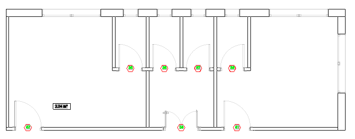
Labeling Window Entities
Use Window labels to number Window entities within the .dwg file.
You can label all Window entities from the BIM drawing or a set of specified Window entities. The selection set can include various BIM entities. Only the Windows entities will be labeled.
To label specified Windows:
Note: Before starting, make sure that the block that you want to use as label exists.
- Isolate the BIM drawing in which you want to label the BIM entities.
- Optionally, specify a default label for Windows entities:
- In the BIM Label Library palette, right-click a label from the Windows category and select Set as Default for Windows.
- Do one of the following:
- On the ribbon, click BIM > Annotate > Label Windows.
- On the menu, click BIM > Label > Label Windows.
- Type BIMLabel.
- If you did not specify a default label, specify the block definition.
- In the graphics area, specify the Windows to label and press Enter.
Note: The selection set can include any BIM entity. Only the Windows entities will be labeled.
To add labels to all Windows in a BIM drawing:
Note: Before starting, make sure that the block that you want to use as label exists.
- Isolate the BIM drawing in which you want to label the BIM entities.
- Optionally, specify a default label for Windows entities:
- In the BIM Label Library palette, right-click a label from the Windows category and select Set as Default for Windows.
- Do one of the following:
- On the ribbon, click BIM > Annotate > Label All Windows.
- On the menu, click BIM > Label > Label All Windows.
- If you did not specify a default label, specify the block definition.
All Windows entities from the drawing are labeled.
Labeling Door Entities
Use door labels to number Door entities within the .dwg file.
You can label all Door entities from the BIM drawing or a set of specified Door entities. The selection set can include various BIM entities. Only the Doors entities will be labeled.
To label specified Doors:
Note: Before starting, make sure that the block that you want to use as label exists.
- Isolate the BIM drawing in which you want to label the BIM entities.
- Optionally, specify a default label for Doors entities:
- In the BIM Label Library palette, right-click a label from the Doors category and select Set as Default for Doors.
- Do one of the following:
- On the ribbon, click BIM > Annotate > Label Doors.
- On the menu, click BIM > Label > Label Doors.
- If you did not specify a default label, specify the block definition.
- In the graphics area, specify the Doors entities to label and press Enter.
Note: The selection set can include various BIM entities. Only the Doors entities will be labeled.
To add labels to all Doors in a BIM drawing:
Note: Before starting, make sure that the block that you want to use as label exists.
- Isolate the BIM drawing in which you want to label the BIM entities.
- Optionally, specify a default label for Doors entities:
- In the BIM Label Library palette, right-click a label from the Doors category and select Set as Default for Doors.
- Do one of the following:
- On the ribbon, click BIM > Annotate > Label All Doors.
- On the menu, click BIM > Label > Label All Doors.
- Type BIMLabel and specify the Doors category.
- If you did not specify a default label, specify the block definition.
All Doors entities from the drawing are labeled.
Access
Command: BIMLabel
Ribbon: BIM > Annotate > Insert Label
The Label Library Palette
FLUIDDESK BIM
The Label Library contains a set of predefined labels for each category of BIM entities.
The Label Library palette lists the labels available in the software, grouped according to their category. For each category of BIM entities, you can specify a default label.
- Clicking the plus sign (+) in front of a category displays the label list.
- Double-clicking the label name starts the BIMLabel command.
- Right-clicking a label name in the Label Library palette displays a context menu.
Use the BIMLabelLibrary command to display the Label Library palette.
To access the Label Library palette:
- Do one of the following:
- On the ribbon, click BIM > Palettes > Labels Library.
- On the menu, click BIM > Label > Labels Library.
- Type BIMLabelLibrary.
To hide the Labels Library:
- Type HideBIMLabelLibrary at the command prompt.
To specify a default label for a category of BIM entities:
- On the Label Library palette, expand the category for which to define a default label. For example, Windows.
- Right-click a label name and select the suitable option. For example, Set as Default for Windows.
Dimensioning BIM Drawings
FLUIDDESK BIM
This section discusses:
Creating Dimensions for BIM Entities
FLUIDDESK BIM
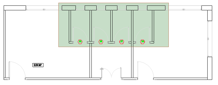
Use the BIMDimensionChain command to create dimension chains for BIM entities. The command automatically detects appropriate dimension points on BIM entities.
Optionally, you can automatically group dimensions within a chain to clearly display opening and wall segments dimensions.
The command uses the dimension standard and tolerance specified in the BIM Settings category of the Options dialog box.
To create a dimension chain:
- Do one of the following:
- On the ribbon, click BIM > Annotate > Dimension Chain
 .
. - On the menu, click BIM > Dimension > Dimension Chain.
- Type BIMDimensionChain.
- On the ribbon, click BIM > Annotate > Dimension Chain
- In the graphics area, specify the BIM entities to dimension and press Enter.
- Specify the suitable alignment:
- Horizontal
- Vertical
- Aligned
- In the graphics area, specify the position of the dimension chain.
Access
Command: BIMDimensionChain
Menu: BIM > Dimension > Dimension Chain
Ribbon: BIM > Annotate > Dimension Chain
Modifying Existing Dimensions for BIM Entities
FLUIDDESK BIM
There are the following methods for modifying dimensions for BIM entities:
- Using grip points
- Using the Properties palette
- Using the BIMDimensionEdit command
Use the BIMDimensionEdit command to modify existing dimension chains.
The command lets you:
- Add dimension points to dimension line
- Delete dimension points from dimension line
- Automatically dimension additional BIM entities within the same dimension chain
- Automatically update the dimension chain when a BIM entity is removed
The specialized tools for modifying dimensions are grouped on the Annotate panel of the BIM ribbon tab.
To add dimension points to a dimension line:
- Do one of the following:
- On the ribbon, click BIM > Annotate > Add Point .
- On the menu, click BIM > Dimension > Dimension Edit > Add Point.
- Type BIMDimensionEdit and specify the Add points option.
- On the ribbon, click BIM > Annotate > Add Point
- In the graphics area, specify the dimension chain to modify.
- In the graphics area, specify the points to dimension and press Enter.
- Specify the index of the dimension line and press Enter. 0 means the first dimension line from the chain.
To delete a dimension point from a dimension chain:
- Do one of the following:
- On the ribbon, click BIM > Annotate > Remove Points
 .
. - On the menu, click BIM > Dimension > Dimension Edit > Remove Point.
- Type BIMDimensionEdit and specify the Remove points option.
- On the ribbon, click BIM > Annotate > Remove Points
- In the graphics area, specify the dimension chain from which to remove dimension points.
- On the BIM model, specify the point to remove.
Note: Make sure to specify only points corresponding to extension lines from the dimension chain.
To dimension additional BIM entities within a specified dimension chain:
- Do one of the following:
- On the ribbon, click BIM > Annotate > Add Entity .
- On the menu, click BIM > Dimension > Dimension Edit > Add Entity.
- Type BIMDimensionEdit and specify the Add Entity option.
- On the ribbon, click BIM > Annotate > Add Entity
- In the graphics area, specify the dimension chain to modify.
- Specify the BIM entities to dimension and press Enter.
Corresponding dimension points are added to the dimension chain.
For example, you can specify a window to consider it in the dimension chain.
To detach a BIM entity from a specified dimension chain:
- Do one of the following:
- On the ribbon, click BIM > Annotate > Remove Entity
 .
. - On the menu, click BIM > Dimension > Dimension Edit > Remove Entity.
- Type BIMDimensionEdit and specify the Remove Entity option.
- On the ribbon, click BIM > Annotate > Remove Entity
- In the graphics area, specify the dimension chain from which to detach BIM entities.
- Specify the BIM entities to detach and press Enter.
The dimension points belonging to the specified BIM entities are removed from the dimension chain.
Access
Command: BIMDimensionEdit
Menu: BIM > Dimension > Dimension Edit
Working with BIM Materials
FLUIDDESK BIM
Using BIM materials you can control the graphical appearance of entities in drawings that you created from the BIM model.
This section discusses:
About Materials
FLUIDDESK BIM
Using BIM materials you can control the graphical appearance of entities in drawings that you created from the BIM model.
The software provides a Materials Library. Materials from the Materials Library specify graphical styles which the software uses to display BIM entities. Each material specifies the graphical style attributes for a section cut and surface of each BIM entity.
Walls with multiple materials.
Graphical style of each material specifies:
- Hatch properties, such as name, scale, rotation, and lineweight
- Edge and boundary lineweight and color,
- Shading color and transparency
Note: You cannot add, remove, or edit materials available in the BIM Material Library.
When you create or refresh BIM drawings, the material styles defined in the CAD software differentiate a section cut from the surface of each entity showing appropriate graphical representation. For the same material, the surface representation is tipically lighter lineweight than cut representation, and uses a different hatch pattern or has no hatch.
For example, a drawing displays a BIM entity of material concrete using a concrete hatch pattern (AR-CONC) if the drawing’s cutting plane cuts through the BIM entity and no hatch when the same BIM entity is visible but the drawing’s cutting plane does not intersect it.
When you load BIM files into the current DWG file, the available materials are loaded as well. For each BIM entity, the Material property in the Properties palette displays the material specified in the BIM file.
The following tools let you display the list of materials from the BIM model entities:
- BIM Material Mapper palette
- BIM Multi Component palette
Mapping BIM Materials
FLUIDDESK BIM
In BIM files, such as .ifc and .rvt, material name is a property of entities of the BIM model. Materials in BIM software represent real materials, such as Steel, Concrete, Glass. They specify the graphical appearance in drawings. Additionally, where the application provides support for it, physical and thermal properties, and additional information, such as manufacturer and cost.
The BIM Material Mapper palette lists the material names that exist in the loaded BIM files and lets you map those BIM material names to the material available in the BIM Drawings Materials Styles Library.
The BIMMaterialMapper command displays the BIM Material Mapper palette.
When you load BIM files into the current DWG file, the available materials are loaded as well. For each BIM entity, the Material property in the Properties palette displays the material specified in the BIM file. After mapping the materials from the BIM file, the Material property of each BIM entity will display the corresponding material name that you mapped to in the Material Library.
When you create or refresh a drawing, and view it isolated on sheet, BIM entities are represented according to the style definition of the material in the Material Library.
After mapping the materials from the BIM file, BIM entities will be represented in drawings according to the style definition available for the corresponding material in the CAD software.
To display the BIM Material Mapper palette:
- Do one of the following:
- On the ribbon, click BIM > Palettes > Material Mapper.
- On the menu, click BIM > Materials > Material Mapper.
- Type BIMMaterialMapper.
To hide the BIM Material Mapper palette:
- Type HideBIMMaterialMapper at the command prompt.
The BIM Material Mapper Palette
The BIM Material Mapper palette displays the list of all materials from all BIM files that you loaded in the current DWG file. For each material from the list, you can select the corresponding material from the materials library available in the CAD software.
Displays options for filtering the materials from the list.
- IFC Materials. Displays only materials from the .ifc files loaded in the current DWG file.
- RVT Materials. Displays only materials from the .rvt files loaded in the current DWG file.
- All. Displays all materials from all BIM files loaded in the current DWG file.
- Mapped. Displays only mapped materials. For mapped materials, a preview displays in the list.
- Not Mapped. Displays only the materials that you have not mapped yet.
- Selected Entities Only. Displays only materials from the selected entities.
To map materials to materials from the CAD software:
- On the BIM Material Mapper palette, for each material from the list of material names that exist as properties of entities in the loaded BIM files, specify from the drop-down list in the Materials Library column the material you wish to map to.
Click and use the available options to filter the material list.
To display materials for specified BIM entities:
- In the graphics area, specify a set of BIM entities.
- On the BIM Material Mapper palette, click and select Selected Entities Only.
For example, if you select a set of walls for which the Material property is set to Concrete, only Concrete appears on the BIM Material Mapper palette.
Using the BIM Navigator
FLUIDDESK BIM
You can import BIM files, such as .ifc and .rvt files to your project and use various tools to modify them.
The BIM Navigator palette groups all tools necessary to import the BIM files and control the visibility of BIM entities in the graphics area.
You can:
- Import BIM files, such as .ifc and .rvt files.
- Control the access to a file. Unlocking the BIM file displays the file content in the graphics area.
- Control the visibility of the entities. You can show or hide entities and categories of entities from the BIM files that you imported in the current drawing.
To access the BIM Navigator palette:
- Do one of the following:
- On the ribbon, click BIM > Palettes > Navigator.
- On the menu, click BIM > Navigator.
- Type BIMNavigator.
The BIM Navigator Palette
The BIM Navigator palette groups the tools necessary to work with the BIM files content.
To display the BIM files in the current drawing and start using them, you must import the files. Once you import the files, the palette contains the following sections:
- BIM Files. Displays the list of BIM files that you imported in the current drawing and informations about the specified file. Unlocking a file displays the content in the graphics area and lists the entities in the Entities section.
- Filters. Displays the filtering tools.
- Entities. Displays contents from each imported BIM file in a tree view grouped according to their category and type. The tree view lets you browse the BIM file entities. Clicking an entity or a category of entities in the tree view selects the entities in the graphics area.
- Drawings. Displays the drawings created from the BIM model grouped according to their type.
BIM Files Category
Displays all files that you imported in the drawing.
File Properties List
Displays all BIM files that you imported in the drawing. These file types are listed:
- .ifc files
- .rvt files
- .rfa files
Right-clicking a file displays the following options:
- Discipline. Lets you associate the BIM model file with the corresponding discipline tag.
- Delete. Deletes the BIM file from the list.
- Unload. Unloads the BIM file
- Reload from. Resets the path to the BIM file.
Imported file properties include the following:
- Model Name: Displays the file name.
-
Visibility (Show or Hide): You can display only certain files in the graphics area. The button symbol indicates whether, in the graphics area, the drawing entities are shown or hidden. You can turn each file on or off independently.
-
Visible
-
Hidden
-
-
Locked or Unlocked: You can protect files so the entities from the model cannot be changed. The locked state prevents unintentional modification. If a file is protected, you cannot change, add, or delete entities from the model. Change the status to unlocked if you want to work with entities from the model.
-
 Locked
 -
 Unlocked
-
General Information
Displays information about the BIM file selected in the list, such as file type and size and the discipline tags. The set of discipline tags varies according to the model.
Disciplines
Lets you control the display of the entities according to the discipline. Click All to select all disciplines or Clear All to cancel the selections.
DIsciplines – impact on views, visibility control of pipes, components and architecture in the model
Filters Category
Filter drop-down list
Displays the list of all available filters. You can rename existing filters or delete unused ones.
Displays a menu with the following options:
- Rename. Renames the specified filter.
- Delete. Deletes the specified filter.

Displays the Data Extraction wizard.
Note: Save your drawing before starting the Data Extraction wizard.
BIM entities
Groups the tools for defining filtering criteria.
Criteria
Lets you specify the selection criteria.
The properties you can apply as selection criteria are: GUID, Name, Description, Predefined Type, Tag, Entity type.
-
Adds criteria to the criteria list.
-
Deletes criteria from the list.
Relational Operators
| Operator | Description | Examples |
|---|---|---|
| == | Equal | All Circles with radius=2.54 |
| != | Unequal | All Circles with radius other than 2.54 |
Group by
Defines the additional parameters to group by. Add as many parameters as necessary. When you add more than one parameters, BIM entities must meet all.
-
Adds the criterion to the criteria list.
-
Deletes the criterion from the criteria list.
The properties you can apply as grouping criteria are: Type, Floor, Space, Category.
Sort
Specifies the criteria according to which you want to sort the BIM entities. Additionally, you can specify an ascending or a descending order.
- Asc. Ascending order.
- Desc. Descending order.
The properties you can apply as sorting criteria are: Name, description, Predefined Type, Tag, and Entity Type.
Discard
Lets you end filter editing without saving the changes.
If the filter has changed since it was last saved, a prompt asks whether to save the changes. Click Yes to save the changes or No to discard them.
Save As
Saves the changes to a new filter.
Save
Saves the changes to the active filter.
Entity Category
Displays the entities of each imported BIM file in a tree view grouped according to their category and type.
Toolbar
Use the buttons in the toolbar at the top of the BIM Navigator palette for navigation and selection options:
- Filter drop-down list:
-
Hide/Show all entities : Shows or hides all entities from all imported BIM files.
-
Expand/Collapse all entities : Expands all categories from all imported BIM files.
Tree View
Displays the entities of each imported BIM file in a tree view grouped according to their category and type.
The sign () in front of a BIM file expands the categories list.
The sign ( ) in front of a BIM file collapses the categories list.
Visibility (Show or Hide): You can display only certain entities or certain categories in the graphics area. The button symbol indicates whether, in the graphics area, the BIM entities are shown or hidden. You can turn each BIM entity on or off independently.
-
Visible
-
Hidden
Drawings Category
Displays the drawings which you created based on the BIM model and sheets on which you have placed them.
Toolbar
| Button |
Function |
|---|---|
|
Place on Sheet |
Places the specified drawing on the sheet |
|
Refresh All |
Refreshes all drawings |
|
Refresh |
Refreshes the drawing displayed in the graphics area |
Drawings and Sheets List
Displays all drawings that you created from the BIM model in a tree view, grouped according to their type. After placing the drawings on sheets, the corresponding sheets are added under the Sheet branch.
The following drawing types are listed in the tree view:
- Plans
- Sections
- Elevations
The tree view lets you browse the drawings and the sheets. Double-clicking a drawing in the tree view displays the drawing in the graphics area.
The sign () in front of a drawing category expands the drawing list.
The sign () in front of a drawing category collapses the drawing list.
Right-clicking a drawing name displays the following options:
| Button |
Function |
|---|---|
| Place on Sheet | Places the currently selected drawing on the sheet |
| Edit Filter | Displays the Filter List dialog box where you can edit the filter applied to the drawing |
| Refresh | Refreshes the current drawing |
| Rename | Renames the current drawing |
| Open/Close | Opens or closes the selected drawing |
| Show/Hide Clipping Box | Shows or hides the clipping box in the current drawing |
| Show/Hide Callouts | Shows or hides the callouts in the current drawing |
| Split drawing | Splits the current drawing into tile views |
| Remove all tile views | Removes all tile views |
| Delete | Deletes the specified drawing |
Right-clicking the name of an open drawing displays the following options:
| Button |
Function |
|---|---|
| Split drawing | Splits the current drawing into tile views |
| Delete all tile views | Deletes all tile views |
Selection Settings
Lets you control the display of the CallOuts symbols and clipping boxes.
Drawings Automation from RVT or IFC Models
FLUIDDESK BIM
You can automatically create annotated and dimensioned 2D DWG drawings, such as plans, sections, and elevations, from a BIM model.
The BIM drawings retain all the BIM information. Additionally, a link with the BIM model is created. When a new version of the BIM model is available, you can automatically update the BIM drawings.
Drawing creation consists of the following steps:
- Create 2D drawings from the BIM model (BIMAutoDrawings)
- Add dimensions (BIMAutoDimensions)
- Place all necessary labels by extracting information from BIM entities (BIMAutoLabels)
- Start Material Mapping (BIMAutoMaterialMapping)
- Place on Sheets (BIMAutoSheets)
You can run each step automatically using a dedicated command. Alternatively, you can run all steps at once using the BIMAutoAll command.
This topic discusses:
- Automatically Generatting All Drawings from a BIM Model
- Automatically Dimensioning BIM Drawings
- Automatically Annotating BIM Drawings
- Automatically Mapping BIM Model Materials
- Automatically Placing Drawings on Sheets
Automatically Generating Annotated Drawings from a BIM Model
FLUIDDESK BIM
Use the BIMAutoAll command to automatically create annotated and dimensioned 2D DWG drawings, such as plans, sections, and elevations, from the BIM model.
Each drawing created from the same BIM model is stored in a separate .dwg file. The command also creates sheets and inserts drawings on it at a specified scale.
BIM drawings retain all the BIM information. Additionally, a link with the BIM model is created. When a new version of the BIM model is available, you can automatically update the BIM drawings.
Each drawing type has a specific graphical display and appears in a different branch in the BIM Navigator.
The command launches successively all steps necessary for BIM drawing creation:
- Creates 2D drawings from the BIM model
- Adds dimensions
- Places all necessary labels by extracting information from BIM entities
- Maps existing BIM model materials to the application materials.
- Places drawings on separate Sheets
You can manually customize automatically generated drawings.
Automatically Generating All Drawings from a BIM Model
FLUIDDESK BIM
Use the BIMAutoDrawings command to automatically create all necessary 2D DWG drawings, such as plans, sections, and elevations, from the BIM model.
Each drawing created from the same BIM model is stored in a separate .dwg file.
BIM drawings retain all the BIM information. Additionally, a link with the BIM model is created. When a new version of the BIM model is available, you can automatically update the BIM drawings.
Each drawing type has a specific graphical display and appears in a different branch in the BIM Navigator.
If the BIM model consists of multiple buildings, during automation, buildings are processed separately. The building name appears on each drawing.
Automatically Dimensioning BIM Drawings
FLUIDDESK BIM
Use the BIMAutoDimensions command to automatically place all necessary dimensions on all 2D DWG drawings, such as plans, sections, and elevations generated from the BIM model.
Each drawing created from the same BIM model is automatically dimensioned based on the information from the BIM model.
When a new version of the BIM model is available, you can automatically update the BIM drawings. You can refresh each drawing individually or all drawings at once. All existing dimensions will be automatically updated.
Automatically Annotating BIM Drawings
FLUIDDESK BIM
Use the BIMAutoLabels command to automatically place all necessary labels on all 2D DWG drawings, such as plans, sections, and elevations generated from the BIM model.
Entities from all drawings created from the same BIM model are automatically labeled based on the information from the BIM model.
When a new version of the BIM model is available, you can automatically update the BIM drawings. You can refresh each drawing individually or all drawings at once.
Automatically Mapping BIM Model Materials to the Application Materials
FLUIDDESK BIM
Use the BIMAutoMaterialMapping command to automatically map BIM material names that exist in the loaded BIM file to the material available in the BIM Drawings Materials Styles Library.
After mapping the materials from the BIM file, the Material property of each BIM entity will display the corresponding material name that you mapped to in the Material Library.
When you create or refresh a drawing, BIM entities are represented using the corresponding hatch pattern. The same representation is used when opening the BIM drawings and when placing on sheets.
Automatically Placing BIM Drawings on Sheets
FLUIDDESK BIM
Use the BIMAutoSheets command to automatically place each 2D drawing created from a BIM model on a separate Sheet.
The command automatically creates all sheets necessary for the drawings created from a BIM model.