
Introduction
When a drawing is complete, you can apply Sheet tabs to design layouts from which to print. Annotative scaling lets you have consistent sizes and scales of text, dimensions, and hatches in printouts.
This chapter discusses:
- Laying Out Drawings on Sheets. Discusses Model and Sheet workspaces and Viewports on layout Sheets.
- Working with Annotative Scales. Explains how to control the size and scale at which annotation entities are displayed and printed.
Laying Out Drawings on Sheets
This section discusses:
- Creating and Managing Sheets
- Working with Viewports on Sheets
- Switching to Model Workspace
- Switching to Sheet Workspace
- Controlling Visibility of Layers in Viewports
- Clipping Viewports on Sheets
- Moving Entities to Another Workspace
Creating and Managing Sheets
You can create a new Sheet or rename, copy, save, or delete existing Sheets.
To create a finished drawing two different working spaces are provided: Model and Sheet.
A Sheet is a page that allows you to set up a printout or plot of your drawing.
You can create up to 255 Sheets of your drawing on individual tabs. The names of the Sheet tabs must be unique.
When you use the Sheet command, you have options to manage Sheet tabs. Several of these options are also available by right-clicking a Sheet tab.
To create a new Sheet:
- Click File > Sheet > New Sheet (or type Sheet and specify the New option).
- Type a name for the Sheet.
To create a new Sheet based on a Sheet in another file:
- Click File > Sheet > Sheet from Template (or type Sheet and specify the Template option).
- In the Select template from file dialog box, select a *.dwt, *.dwg, or *.dxf file, then click Open.
- In the Sheet List dialog box, select a Sheet name and click OK.
- The Sheet and all entities from the specified file are inserted in the drawing.
To copy a Sheet:
- Type Sheet at the command prompt.
- Specify the Copy option.
- Type the name of the Sheet to copy.
- Type a name for the Sheet.
To rename a Sheet:
- Type Sheet.
- Specify the Rename option.
- Type the name of the Sheet to rename.
- Type a name for the Sheet.
To save a Sheet as a drawing template file:
- Type Sheet.
- Specify the Saveas option.
- Type the name of the Sheet to save as a template.
- The template file is saved without Block definition information and unused drawing properties such as Layers and LineStyles.
To activate a Sheet:
- Type Sheet.
- Specify the Activate option.
- Type the name of the Sheet to activate.
To delete a Sheet:
- Type Sheet.
- Specify the Delete option.
- Type the name of the Sheet to delete.
To list all active Sheets:
- Type Sheet.
- Specify the ? option.
- The active Sheets are listed in the command window.
 You can turn on and off the display of the Model and Sheet tabs. Click Tools > Options. Click Drawing Settings, expand Display, and select or clear Show Model and Sheet tabs.
Access
Command: Sheet
Menu: File > Sheet
Working with Viewports on Sheets
The Viewport command creates and controls multiple tiled views on Sheets, called Viewports.
Use the following methods to create non-rectangular Viewports:
- Convert a closed entity, such as a Circle, an Ellipse, a Spline, a Region, or a closed PolyLine into a Viewport.
- Draw the Viewport boundaries in the same way as drawing a polyline.
You can combine Viewports of different shapes to create various Viewport configurations within a Sheet.
Example:
Viewports on Sheets are different than ViewTiles in model workspace which are created using the ViewTiles command.
You can create, erase, move, copy, scale, and stretch Viewports on Sheets.
You cannot use the Viewport command in the Model tab.
To activate a Sheet:
- Click a Sheet tab (if the Model tab is active).
To create a rectangular Viewport:
- Type Viewport at the command prompt.
- Click in the graphics area to set the first and second Viewport corner.
To create two, three, or four rectangular Viewports:
- Type Viewport at the command prompt.
- Specify the 2, 3, or 4 option depending on how many viewports you want to add to the current Sheet.
- Specify an option for the arrangement (Horizontal or Vertical, for example).
2 Viewports:


3 Viewports:


4 Viewports:


- Click in the graphics area or type a value to set the corners of the viewport, or specify the Fit option.
To create a Viewport that fills the Sheet to the edges of the printable area:
- Type Viewport.
- Specify the Fit option.
When the printable area is turned off, the Viewport fits the entire Sheet.
To convert a closed PolyLine, Circle, Ellipse, closed Spline, or Region into a non-rectangular Viewport:
- Type Viewport.
- Specify the Entity option.
- In the graphics area, select the entity to convert into a Viewport.
To create a non-rectangular Viewport with a polygonal boundary:
The Polygonal option lets you draw an irregular shape that defines the boundary of a Viewport.
- Type Viewport.
- Specify the Polygonal option.
- Click in the graphics area to set the first point that defines the boundary.
- Define the rest of the boundary. Do one of the following:
- Click in the graphics area to specify additional points.
- Specify the Arc option. Follow the prompts to create arc segments for the Viewport boundary. The options for creating arc segments are similar to those of the PolyLine command.
- Specify the Length option. Follow the prompts to create a line segment of a specified length at the same angle as the previous segment. This option is useful to append a straight segment of a specified length tangent to a previous arc segment.
- Specify the Close option to close the boundary.
- Specify the Undo option to undo the most recent segment during the creation of the Viewport boundary.
To turn on Viewports:
- Type Viewport.
- Specify the On option.
- In the graphics area, select the Viewports to turn on.
The model displays in the selected Viewports.
To turn off Viewports:
- Type Viewport.
- Specify the Off option.
- In the graphics area, select the Viewports to turn off.
The model does not display in the selected Viewports.
To set Viewport print options:
- Type Viewport.
- Specify the Shaded view option.
- Specify an option:
- Current display. Prints the Viewport as it is displayed on screen.
- Hidden. Prints the Viewport with hidden lines removed.
- Rendered. Prints the Viewport rendered.
- Wireframe. Prints the Viewport as wireframe.
- In the graphics area, select the Viewports to which the settings should apply.
To lock or unlock a Viewport:
The Lock option prevents changes to the zoom scale factor when you work in locked Viewports in Model workspace.
- Type Viewport.
- Specify the Lock option.
- Specify On to lock or Off to unlock.
- In the graphics area, select the Viewports to which the settings should apply.
To restore Viewport configurations saved using the Viewport command:
- Type Viewport.
- Specify the Restore option.
- Do one of the following:
- Type the name of the Viewport configuration to restore.
- Specify the ? option to list Viewport configurations.
- Specify the Active model configuration option.
To align the view in one Sheet Viewport with the view in another Viewport:
- Activate a Sheet tab and the Sheet workspace.
- Click View > View Tiles > Horizontal or View > View Tiles > Vertical (or type Viewport).
- Specify the Align option.
- Specify Horizontal or Vertical alignment mode.
- In a Viewport area, specify the base point for the alignment.
- In another Viewport area, specify the point to which to align the Viewport from step 5 to.
The Viewport from step 5 aligns either horizontally or vertically.
Use EntitySnaps when specifying the base point and alignment point to reference existing geometry. Make sure Ortho Mode is turned on when moving a Viewport that you have already aligned to another one.
Access
Command: Viewport
Switching to Model Workspace
When working in a Sheet, the ModelMode command lets you toggle from Sheet workspace to Model workspace.
You can draw or edit entities in Viewports although your working space is a layout Sheet.
If you have multiple tiled views on a Sheet, you activate a specific one by clicking it.
To switch back to Sheet workspace, use the SheetMode command.
You cannot use the ModelMode command in the Model tab.
Access
Command: ModelMode
Switching to Sheet Workspace
When working on a Sheet, the SheetMode command lets you toggle from Model workspace to Sheet workspace.
In Sheet workspace, you display views of the model in Viewports, create borders, insert title Blocks, or add annotations, part lists, or legends, for example.
Sheets represent the paper layout of a drawing. You can create multiple layouts on Sheet tabs.
To switch to Model workspace, use the ModelMode command.
You cannot use the SheetMode command in the Model tab.
Access
Command: SheetMode
Controlling Visibility of Layers in Viewports
The ViewportLayer command controls Layer visibility within Viewports on Sheets. The command behaves like features of the Layer command, except that it affects only specified Viewports on Sheets.
The command is supported only for Sheet tabs and works only on the Model side of Viewports on Sheets.
To activate a Viewport on a Sheet tab:
- Select a Sheet tab.
- Click inside the Viewport to select the Viewport where you want to suppress Layers.
To suppress Layers in Viewports on Sheets:
You can suppress one or multiple Layers in one or multiple Viewports on Sheets. You can make a layer in a specific Viewport invisible on screen and on print and plot output. Entities on suppressed Layers are not rebuilt.
- Type ViewportLayer at the command prompt.
- Specify the Frozen option.
- In the graphics area, select entities or type the Layer names to freeze.
The command accepts wildcard characters where * freezes all Layers.
- Specify an option:
- All: Freezes the specified Layers in all existing Viewports on the current Sheet tab.
- Select: Lets you specify the Viewports in which to freeze the specified Layers.
- Current: Freezes the specified Layers only in the current Viewport.
- Press Enter to end the command.
The Layers you selected disappear.
To thaw Viewport Layers:
You can bring back frozen Layers in one or multiple Viewports on Sheets.
- Type ViewportLayer.
- Specify the Thaw option.
- Type Layer names to thaw.
- Specify an option:
- All: Thaws the specified Layers in all existing Viewports on the current Sheet tab.
- Select: Lets you specify the Viewports in which to thaw the specified Layers.
- Current: Thaws the specified Layers only in the current Viewport.
- Press Enter to end the command.
To reset Viewport Layers on Sheets:
You can set the visibility of Layers in one or multiple Viewports to their default settings.
- Type ViewportLayer.
- Specify the Reset option.
- In the graphics area, select entities or type the Layer names to reset.
- Specify an option:
- All: Resets all existing Viewports on the current Sheet tab.
- Select: Lets you specify the Viewports in which to reset the specified Layers.
- Current: Resets only in the current Viewport.
- Press Enter to end the command.
To create one or more Layers that are suppressed in all Viewports on Sheets:
- Type ViewportLayer.
- Specify the Frozen from New option.
- Type the Layer names to suppress.
- Press Enter to end the command.
- The Layers you suppress disappear.
To suppress or undo suppression of one or more Layers in newly created Viewports:
- Type ViewportLayer.
- Specify the Visibility default option.
- In the graphics area, select entities or type the Layer names to suppress or undo suppression.
- Specify Frozen to suppress or Thawed to undo suppression of the Layers.
- Press Enter to end the command.
- The Layers you suppress disappear.
Access
Command: ViewportLayer
Clipping Viewports on Sheets
The ClipViewport command lets you clip the display of Viewports on the current Sheet at irregular shapes.
When you create a Viewport on a Sheet, it has a rectangular boundary shape by default. Use the command to replace the rectangular shape, either by specifying a closed entity as the new boundary, or by drawing a new polygonal boundary by pointing to the graphics area.
To clip a Viewport on a Sheet by specifying a clipping entity:
- Activate a Sheet tab so you are in SheetMode.
- Click Modify > Clip > Viewport (or type ClipViewport).
- Select the Viewport to clip.
Note: You cannot clip a Viewport which was created with the Entity option.
- Select the entity that defines the clipping boundary. You can select a Circle, Ellipse, closed PolyLine, or closed Spline.
The selected boundary clips the Viewport and replaces the rectangular boundary.
To clip a Viewport on a Sheet by pointing to a polygonal shape:
- Activate a Sheet tab.
- Click Modify > Clip > Viewport (or type ClipViewport).
- Select the Viewport to clip.
Note: You cannot clip a Viewport which was created with the Entity option.
- Specify the Polygonal option.
- Select the first point of the irregular shape.
- Continue to select points to define the boundary or specify an option:
- Arc: Draw arc segments of the shape. You can use the arc options as you can in the PolyLine command.
- Close: Closes the polygonal shape. The new boundary clips the Viewport.
- Length: Draws a straight segment of a specified length in the same direction as the previous segment (tangentially if it was an Arc).
- Undo: Removes the previous segment.
- Press Enter to close the polygonal shape.
The new boundary clips the Viewport.
You cannot use the ClipViewport command in the Model tab.
Access
Command: ClipViewport
Menu: Modify > Clip > Viewport
Ribbon: Sheet > Viewports > Viewport Clip 
Moving Entities to Another Workspace
Use the ChangeSpace command to move entities from Model workspace to Sheet workspace and vice versa.
For example, you can use the command to move title blocks or part lists from Model workspace to Sheet workspace.
You must be on a Sheet tab to use the command.
The selected entities are scaled in the new workspace to maintain visual appearance. The entity scaling is determined by the Viewport that is active during command execution.
To move entities to another workspace:
- Click a layout Sheet.
- Make sure that you are in the correct workspace to specify the entities to transfer.
- If you are in Model workspace, double-click outside the Viewport to enter Sheet workspace.
- If you are in Sheet workspace, double-click inside the Viewport to enter Model workspace.
- Type ChangeSpace at the command prompt.
- In the graphics area, select entities to transfer.
- Press Enter.
Access
Command: ChangeSpace
Working with Annotative Scales
This section discusses:
- Applying Annotative Scaling
- Assigning Annotative Scales to Supported Entities
- Assigning the Active Annotative Scale to Supported Entities
- Removing the Active Annotative Scale from Supported Entities
- Resetting the Scale Representations of Annotative Entities
- Updating the Style Settings of Annotative Entities
Applying Annotative Scales
When you add text, dimensions, hatches, and blocks to a drawing, you can apply the annotative scaling property. It is referred to as annotative entities. Annotative scaling lets you achieve consistent and uniform sizes and scales of text, dimensions, and hatches for printouts.
Annotative entities display is controlled by the active annotation scale on the Model tab and the annotation scale property of Viewports on layout Sheets. Click Annotation on the status bar to set and control annotation scales.
Annotative entities and styles control the size and scale at which annotation entities are displayed and printed:
- For Notes, SimpleNotes, and Dimensions, define TextStyles and DimensionStyles as annotative styles to apply annotative scaling.
- For Hatches, Blocks, and BlockAttributes, you define the annotative scaling property when you create these entities.
- You can also make all these annotative entities independent from the style they use after you created them.
This topic discusses:
- Supported Entities and Styles
- Annotative Scaling Properties
- Annotation Button on the Status Bar
- Commands for Annotative Scaling
Supported Entities and Styles
You can apply annotative scaling to the following entity types:
- Text (Notes and SimpleNotes)
- Dimensions and Tolerances
- Hatches
- Block definitions and BlockAttribute definitions
The following styles can be annotative:
- TextStyles
- DimensionStyles
Annotative styles create annotative entities. The entities based on annotative styles automatically use annotative scaling. However, Notes, SimpleNotes, and Dimensions can be annotative although the style they use is not annotative. Using annotative styles avoids making individual text entities annotative after you created them.
Notes and SimpleNotes
Notes (including Leader text) and SimpleNotes use annotative scaling if the TextStyle you apply is defined to support annotative scales.
To make TextStyles annotative, in the Options dialog box, click Drafting Styles > Text > Annotative Scaling (see Working with TextStyles).
You can individually make Notes and SimpleNotes annotative if the associated TextStyle is non-annotative (see Annotative Scaling Property).
Dimensions and Tolerances
Dimensions and Tolerances use annotative scaling if the DimensionStyle you apply is defined to support annotative scale.
To make DimensionStyles annotative, in the Options dialog box, click Drafting Styles > Dimension > Fit > Dimension Scale > Annotative Scaling (see Working with Dimension Styles).
You can make individual Dimensions and Tolerances annotative if the associated DimensionStyle is non-annotative (see Annotative Scaling Property).
Hatches
Hatches use annotative scaling if you select the option when creating or editing hatches or filled areas (using the Hatch, FillArea, or EditHatch commands).
This property ensures similar pattern sizes in Viewports on layout Sheets.
Blocks and BlockAttributes
Block insertions and their associated BlockAttributes use annotative scaling if you select the option when creating Blocks and BlockAttributes (using the MakeBlock and MakeBlockAttribute commands).
Annotative Scale Property
The entity types that support annotative scaling include the Annotative Scale property. You can modify the property using the Properties palette.
To make individual entities annotative:
- In the graphics area, specify an entity that supports annotative scaling.
- In the Properties palette, set the Annotative property to Yes.
Additional options are shown. In Annotative Scale, set the active annotative scale.
- Click Edit annotation scales
 to add annotation scales to the entity.
 - In the Annotation Entity Scale List dialog box:
- Click Add to add annotation scales to the entities’ scale list from the drawing scale list.
- Click Delete to remove annotation scales from the entities’ scale list.
- Click OK.
- If you selected a Note, SimpleNote, or BlockAttributeDefinition, set options in the Properties palette:
- Sheet text height. If the TextStyle is defined for annotative scaling: A numeric value sets the font at a fixed height that you cannot change when inserting a Text entity that uses the selected Font. Set Height to 0.00 if you need to change the TextStyle height.
- Match orientation to Sheet. Specifies whether the orientation of Notes and SimpleNotes in Viewports of layout Sheets follows the Sheet orientation.
Annotative Button on the Status Bar
On the status bar, click Annotative to access options to control annotative scales and display modes for annotative entities.
At the top of the flyout, the drawing scale list displays (when the Model tab is active, or you activated the model workspace on a layout Sheet). The active scale is marked in the list; it also displays next to the Annotation button.
You can click:
- A list entry to activate an annotative scale.
- Scale List to customize the drawing scale list.
On the flyout, you can set the following options:
- Display reference scales. If you attached externally referenced drawings (References) to the current drawing, the scale lists of the References may have scales defined, that are not available in the scale list of the host drawing. The option determines whether to show or hide the specific scales originated in referenced drawings. It is only available when the drawing scale list displays on the flyout (see above).
- Show all annotation representations for selected entities. Specifies whether annotative entities, if selected, show all representations of the annotation scales assigned to them, or only the original scale.
- Show annotation entities for current scale only. Specifies whether only annotation entities that support the active annotation scale are displayed. Otherwise all annotative entities regardless of scales they support are displayed. This setting is saved individually for the Model tab and each Sheet tab.
Commands for Annotative Scaling
You can apply the following commands to control annotative scales for entities that support:
- AnnEntityScale. Assigns annotative scales to supported entities.
- AnnEntityScaleAdd. Assigns the active annotative scale to supported entities.
- AnnEntityScaleRemove. Removes the active annotative scale from supported entities.
- AnnReset. Resets the position of scale representations of annotative entities.
- AnnUpdate. Updates the style settings of annotative entities.
See also: Customizing the Drawing Scale List
Assigning Annotative Scales to Supported Entities
Use the AnnEntityScale command to add and remove annotation scales for specified annotative entities.
You can assign multiple scales to annotative entities. This is referred to as scale representations.
When you hover over an annotative entity, an icon displays near the pointer. The icon ![]() indicates that the entity currently supports only one annotative scale; the icon
indicates that the entity currently supports only one annotative scale; the icon ![]() indicates that the entity currently supports two or more annotative scales.
indicates that the entity currently supports two or more annotative scales.
You can also remove obsolete annotation scales.
To assign annotation scales to supported entities:
- Click Modify > Annotation Scaling > Add/Remove Scales (or type AnnEntityScale).
- In the graphics area, specify annotative entities.
- Press Enter.
The Annotation Entity Scale List dialog box opens. It displays the annotation scales used by the specified entities.
- To customize the scale list display, select an option:
- Show all scales. Displays all scales defined in the drawing.
- Show only common scales. Displays the scales that are currently used by all selected annotative entities.
- Click Add.
The Scale List dialog box opens and displays the drawing scale list.
- Select one or more scales from the list and click OK.
- Click OK.
To remove annotation scales from supported entities:
- Click Modify > Annotation Scaling > Add/Remove Scales (or type AnnEntityScale).
- In the graphics area, specify annotative entities.
- Press Enter.
- In the dialog box, select one or more annotative scales.
- Click Delete.
- Click OK.
Note: You can use the AnnEntityScale command only on the Model tab or in the Model workspaces on layout Sheets.
Access
Command: AnnEntityScale
Menu: Modify > Annotation Scaling > Add/Remove Scales
Assigning the Active Annotative Scale to Supported Entities
Use the AnnEntityScaleAdd command to update annotative entities to support the drawing’s active annotation scale.
To set the active annotation scale:
- Click Annotation on the status bar.
- From the list which represents the drawing scale list, select the annotation scale to activate.
The drawing’s active annotation scale displays next to the Annotation button on the status bar.
To assign the active annotative scale to supported entities:
- Click Modify > Annotation Scaling > Add Current Scale (or type AnnEntityScaleAdd).
- In the graphics area, specify annotative entities.
- Press Enter.
The command reports the number of updated entities.
Note: You can use the AnnEntityScaleAdd command only on the Model tab or in the Model workspaces on layout Sheets.
Access
Command: AnnEntityScaleAdd
Menu: Modify > Annotation Scaling > Add Current Scale
Removing the Active Annotative Scale from Supported Entities
Use the AnnEntityScaleRemove command to remove the drawing’s active annotation scale from the entities’ annotation scales.
To set the active annotation scale:
- Click Annotation on the status bar.
- From the list which represents the drawing scale list, select the annotation scale to activate.
The drawing’s active annotation scale displays next to the Annotation button on the status bar.
To remove the active annotative scale from supported entities:
- Click Modify > Annotation Scaling > Remove Current Scale (or type AnnEntityScaleRemove).
- In the graphics area, specify annotative entities.
- Press Enter.
The command reports the number of entities from which the active annotation scale was removed.
Note: You can use the AnnEntityScaleRemove command only on the Model tab or in the Model workspaces on layout Sheets.
Access
Command: AnnEntityScaleRemove
Menu: Modify > Annotation Scaling > Remove Current Scale
Resetting the Scale Representations of Annotative Entities
Use the AnnReset command to reset all scale representations of specified annotative entities to their original position.
Alternate scale representations are the scales assigned to annotative entities. You can change the position of scale representions individually using EntityGrips.
To reset the scale representations of annotative entities:
- Click Modify > Annotation Scaling > Match Scale Positions (or type AnnReset).
- In the graphics area, specify annotative entities.
- Press Enter.
The scale representations of the specified annotative entities are reset to the position of the current scale representation.
Note: You can use the AnnReset command only on the Model tab or in the Model workspaces on layout Sheets.
Access
Command: AnnReset
Menu: Modify > Annotation Scaling > Match Scale Positions
Updating the Style Settings of Annotative Entities
Use the AnnUpdate command to update existing annotative entities (Notes, SimpleNotes, BlockAttributes, Dimensions, and Tolerances) to match updated TextStyle or DimensionStyle settings.
To update the style settings of annotative entities:
- Click Modify > Annotation Scaling > Update Annotation Style Settings (or type AnnUpdate).
- In the graphics area, specify annotative entities.
- Press Enter.
The annotative entities are updated and use the current style settings.
Note: You can use the AnnUpdate command only on the Model tab or in the Model workspaces on layout Sheets.
Access
Command: AnnUpdate
Menu: Modify > Annotation Scaling > Update Annotation Style Settings
Printing and Plotting Drawings
You can print drawings on a printer or plotter. You can also print drawings to a file.
This chapter discusses:
- Previewing Printouts
- Printing and Plotting
- Printing Quickly
- Customizing the Drawing Scale List
- Setting Custom Paper Sizes for Printing
- Managing PrintStyle Tables
- Managing Named PrintStyles
- Converting PrintStyles
Previewing Printouts
You can see how the drawing will look when it is printed or plotted.
To preview a printout:
- Click File > Print Preview (or type Preview).
- Use the toolbar to:
-
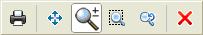
- Print or plot the drawing.
- Pan the preview.
- Zoom in or out (the default state).
- Zoom to window specified by two opposite points on the preview.
- Zoom to the original view of the preview.
- Close the preview.
Note: It is required that a printer has already been assigned to the current Model or layout Sheet. Use the PageLayout command to assign a printer to the Model or Sheet.
Access
Command: Preview
Menu: File > Print Preview
Printing and Plotting
You can print the drawing on a printer or plotter. You can also print the drawing to a file.
To print or plot a drawing on a printer or plotter, or to print a drawing to a file:
- Do one of the following:
- On the application menu, click Print > Print.
- On the menu, click File > Print.
- Type Print.
- Under Printer/Plotter:
- In Name, select an output device. Printers and plotters available on your system are listed. PDF, JPG, PNG, and SVG are also listed. These built-in plotters print to file in the specified format.
- If you selected a built-in PDF printer, click PDF Options to specify the properties of the PDF file.
See PDF Options.
- Select Print to file for output to a file instead of to the printer.
- In Copies, set the number of copies to print.
- In Paper size, select a size from the international standardized paper size formats and printer-specific paper formats.
- Under Orientation:
- Click Portrait or Landscape to set the orientation.
- Select Inverse to reverse the output direction.
- Under Range, set the area to print.
- Select one of the following options:
- All geometry. Prints the range that is determined by the bounding box of all visible entities.
- Drawing boundary / Sheet. Prints the range that is determined by the drawing boundaries (when the Model is active) or the range that is determined by the Sheet size definition (when a Sheet tab is active).
- Named view. Prints the view you select. This option is available only if named views exist in the drawing.
- Current view. Prints the drawing that is visible on screen.
- Specify. Click Window to specify two opposite points for the print boundaries in the graphics area.
- Select Print only within specified window to cut entities at the boundaries of the specified print range on the printout regardless of whether there is remaining space on the output sheet.
- Select one of the following options:
-
Note: The Print selected Sheets option and the Select Sheets button are available only if a Sheet tab is active.
- Under Scale, set the output scale.
- Select one of the following options:
- Select Fit to paper size to apply no specific scaling.
- Clear Fit to paper size, then select a scale from the Scale list.
- Clear Fit to paper size, select User-defined from the Scale list, and set the ratio between paper units (in Millimeters or Inches) to drawing units.
- Select or clear Scale LineWeights.
- Select one of the following options:
- Under Offset, select Print on center of paper to adjust the output with equal margins at the top, bottom, left, and right. Otherwise, set the X and Y margins.
Note: The option Print on center of paper is not available if a Sheet tab is active. Adjust the X and Y margins of the printout as needed.
- Under PrintStyle table:
- Select a PrintStyle table.
- Click New to create a new PrintStyle.
- Click Edit to modify the selected PrintStyle.
- Under Shaded views, set:
- Shade print. Applies a shade mode when printing: As displayed, Wireframe, Hidden, or Rendered (available when the Model tab is active).
- Print quality. Applies a quality level when printing. The available options depend on the selected printer.
- DPI. Sets the number of dots per inch printed depending on the Print quality setting.
- Under Options, set advanced printing preferences:
- Hide geometry on sheet. Specifies whether the model geometry in Viewports is printed with hidden lines removed. The option is available only from a Sheet tab.
- Print in background. The output is processed in the background so you can continue working in the drawing.
- Print Sheet last. Specifies what to print first: the model geometry in Viewports or the Sheet geometry. The option is available only from a Sheet tab.
- Save changes on Sheet. Saves the changes you make in the dialog box to the Sheet.
- Use assigned LineWeight. Prints entities in the LineWeights assigned in the Layers. This option is available only if Use assigned Print Styles is cleared.
- Use assigned Print Styles. Determines whether PrintStyles applied to Layers and entities are printed. Assigned LineWeights are also printed.
-
Print stamp on. Determines whether to print a print stamp along the drawing. Click Print Stamp Settings
 to open the Print Stamp dialog box where you can specify the information to display in the print stamp and the text properties.
- Print transparency. Determines whether to print transparencies applied to entities.
- Optionally, use the following:
- Print Preview. Lets you see how the output will look with the current settings. Opens the Print Preview dialog box.
- Apply to Sheet. Applies the current dialog box settings to the current layout sheet.
- Click OK to print the document.
PDF Options
The PDF Options dialog box lets you manage the quality of the PDF file, the data to include in the PDF file.
It is a subdialog of the Print dialog box.
To set PDF options for printing:
- In the Print dialog box, in Printer/plotter, in Name, select PDF.
- Click PDF Options.
- In the PDF options dialog box, do the following:
To control the quality:
- Vector quality. Lets you specify the resolution of vector graphics within the PDF file. For printing from a viewer, use resolutions matching the printer output. For on-screen viewing, you can use resolutions above 2400 dpi.
- Raster image quality. Lets you specify the resolution of raster images. For printing from a viewer, use resolutions matching the printer output. For on-screen viewing, you can use resolutions above 2400 dpi.
- Merge control. Lets you specify whether overlapping lines overwrite or merge.
To control the data to include in the PDF file:
- Use layers in PDF (PDF v1.5 or higher). Lets you turn on and off layers when printing or viewing the PDF file.
- Add hyperlinks. Lets you convert sheet links into hyperlinks in multi-sheet PDF files.
To manage TrueType fonts from the drawings:
-
Embed True Type fonts used in the drawing. Captures True Type fonts used in the drawing’s annotations and includes them in the PDF file. When viewing the PDF file, the fonts are read directly from the PDF file and the PDF viewer should not substitute them. This option increases the PDF file size.
Exceptions:
- Fonts that are not TrueType fonts
- Vertical Asian fonts
- Optimized. Specifies whether to use True Type font-related optimization when creating the PDF file. This may influence the output performance, but reduces the file size.
- Convert all True Type texts used in the drawing. Lets you convert all text to geometry during the export to PDF file when you cannot include your TrueType fonts in the PDF file. The text in the PDF file is identical to the text on the drawing.
-
SHX text as geometry. Lets you convert SHX fonts to geometry. Thus, annotations that use SHX fonts are represented using geometric entities, such as lines and arcs. Otherwise, the SHX-based annotations appear as text lines in the PDF file using a corresponding or similar TrueType font, which lets you select annotations in the PDF file as text objects.
The shape fonts are always printed as geometry regardless of the selection made.
Note: The Search tool from the PDF viewer can locate a specified text in the file.
- Click OK.
Access
Command: Print
Application Menu: Print > Print
Menu: File > Print
Keyboard Shortcut: Ctrl + P
Keyboard Shortcut: Command + P
Printing Quickly
You can print the current view of a drawing to the printer that is set as the default output device in your operating system (OS).
The QuickPrint command is executed immediately without further prompting. It prints the current view of the graphics area, scaling it so that it is scaled to fit the default paper size, and the output is centered on the sheet.
Other settings and additional options that you can set when using the Print command (such as print styles and shaded view print options) are ignored.
To print the current view of the graphics area:
- Type QuickPrint at the command prompt.
The output to the default printer is launched immediately.
Access
Command: QuickPrint
Managing PageLayouts
PageLayouts are printing configurations stored in the drawing file. You can define PageLayouts to apply as print defaults for the Model and for Sheets.
Use the PageLayout Manager to create new PageLayouts. During the creation, you can specify the following:
- PageLayout name
- A printer
- A paper size
- Drawing orientation
At any time, you can modify the specified information.
The PageLayout command displays the PageLayout Manager.
To open the Page Layout Manager dialog box:
- Click File > Page Layout Manager (or type PageLayout).
The dialog box displays the user-defined print configurations associated with the Model or the active Sheets. The Settings section displays printer related information about the selected user-defined PageLayout.
At the top of the dialog box the name of the active PageLayout is displayed.
At the bottom of the dialog box, Show dialog box on creation of new sheets lets you determine whether you want the Page Layout Manager dialog box to open automatically when you create a new Sheet.
To create a new PageLayout:
- In the Page Layout Manager dialog box, click New.
- In the Page Layout Manager dialog box, click New
 .
. - In the New Page Layout dialog box:
- Type a Name for the new PageLayout.
- Select an existing PageLayout in Based on. The new PageLayout will be based on your selection.
- Click OK.
- In the Page Layout dialog box:
- Set the printer or plotter, select a paper size, specify print scale and print range, and set additional options.
For detailed information about the Page Layout dialog box, see Setting Up PageLayouts.
- Click OK.
- Click Save.
- Set the printer or plotter, select a paper size, specify print scale and print range, and set additional options.
- Click Close.
To edit a PageLayout:
- In the Page Layout Manager dialog box, select a PageLayout.
-
Click Edit.
Click Tools
 , then Edit.
 - In the Page Layout dialog box:
- Set the printer or plotter, select a paper size, specify print scale and print range, and set additional options.
For detailed information about the Page Layout dialog box, see Setting Up PageLayouts.
- Click OK.
- Click Save.
- Set the printer or plotter, select a paper size, specify print scale and print range, and set additional options.
- Click Close.
To activate a PageLayout:
- In the Page Layout Manager dialog box, select a PageLayout that you want to use for the current sheet.
- Click Activate.
- Right-click, then click Activate.
- Click Close.
To import a PageLayout:
- In the Page Layout Manager dialog box, click Import to load PageLayouts contained in other drawing files (.dwg), drawing exchange files (.dxf), or drawing template files (.dwt).
- In the Page Layout Manager dialog box, click Tools > Import to load PageLayouts contained in other drawing files (.dwg), drawing exchange files (.dxf), or drawing template files (.dwt).
- In the Open dialog box, select the file name that contains the PageLayouts you want to import and click Open.
- In the Import Page Setups dialog box, select a PageLayout name.
The PageLayout is added to the PageLayouts of the current drawing.
- Click OK.
- Click Close.
To delete a PageLayout:
- In the Page Layout Manager dialog box, select a PageLayout.
- Click Delete.
- Click Delete
 .
. - Click Close.
Access
Command: PageLayout
Menu: File > Page Layout Manager
Shortcut: Right-click the Model or a Sheet tab and select Page Layout Manager
Setting Up PageLayouts
Use the Page Layout dialog box to configure and edit a new or existing PageLayout.
The dialog box is invoked from the Page Layout Manager.
The dialog box is the same as used by the Print command, but with the Page Layout options section disabled. This section is meaningless for PageLayout configurations.
To set up PageLayouts:
- In the Page Layout dialog box, under Printer/plotter:
- In Name, select an output device. Printers and plotters available on your system are listed. PDF, JPG, PNG, and SVG are also listed. These built-in plotters print to file in the specified format.
- Click Properties to set up the printer or plotter in the dialog box provided by the printer’s driver.
If you selected a built-in printer (PDF, PNG, JPG, SVG, or DWF), you can set custom paper sizes.
If you selected a built-in printer (PDF, PNG, JPG, SVG, or DWF), you can set custom paper sizes.
- Select Print to file for output to a file instead of to the printer.
- In Paper size, select a size from the international standardized paper size formats and printer-specific paper formats.
- Under Orientation:
- Select Portrait or Landscape format.
- Select Print inverse to reverse the output direction.
- Under Range, set the area to print.
- Select one of the following options:
- All geometry. Prints the range that is determined by the bounding box of all visible entities.
- Drawing boundary (available only when the Model tab is active). Prints the range that is determined by the drawing boundaries.
- Sheet (available only when a Sheet tab is active). Prints the range that is determined by the Sheet size definition.
- Named view. Prints the view you select. This option is available only if named views exist in the drawing.
- Specify. Click Window to select two opposite points for the print boundaries in the graphics area.
- Current view. Prints the drawing that is visible on screen.
- Select Print only within specified window to cut entities at the boundaries of the specified print range on the printout regardless of whether there is remaining space on the output sheet.
- Select one of the following options:
- Under Scale, set the output scale.
- Select one of the following options:
- Select Fit to paper size to apply no specific scaling. This option is available only if the Model tab is active.
- Clear Fit to paper size, then select a scale from the Scale list.
- Clear Fit to paper size, select User-defined from the Scale list, and set the ratio between paper units (in Millimeters or Inches) to drawing units.
- Select or clear Scale LineWeights. This option is available only if a Sheet tab is active.
- Select one of the following options:
- Under Offset, select Print on center of paper to adjust the output with equal margins at the top, bottom, left, and right. Otherwise, set the X and Y margins.
Note: The option Print on center of paper is not available only if a Sheet tab is active. Adjust the X and Y margins of the printout as needed.
- Under PrintStyle table:
- Select a PrintStyle table.
- Click New to create a new PrintStyle.
- Click Edit to modify the selected PrintStyle.
- Under Shaded views, set:
- Shade print. Applies a shade mode when printing: As displayed, Wireframe, Hidden, or Rendered (available when the Model tab is active).
- Print quality. Applies a quality level when printing. The available options depend on the selected printer.
- DPI. Sets the number of dots per inch printed depending on the Print quality setting.
- Under Options, set the following:
- Hide geometry on sheet. Specifies whether the model geometry in Viewports is printed with hidden lines removed. The option is available only from a Sheet tab.
- Print sheet last. Specifies what to print first: the model geometry in Viewports or the Sheet geometry. The option is available only from a Sheet tab.
- Use assigned LineWeight. Prints entities in the LineWeights assigned in the Layers. This option is available only if Use assigned print styles is cleared.
- Use assigned Print Styles. Determines whether PrintStyles applied to Layers and entities are printed. Assigned LineWeights are also printed.
- Display Print Styles. Determines whether the active PrintStyle should be applied when displaying the drawing in the graphics area. Activate this option to preview the visible effects of the PrintStyle Table definitions (such as LineStyle, LineWeights, LineColors). The option applies to layout sheets and possibly to the model if they use the active PrintStyle.
- Print transparency. Determines whether to print transparencies applied to entities.
- Optionally, click Print Preview to see how the output will look with the current settings. The option opens the Print Preview dialog box.
- Click Save Page Layout to save the configuration settings.
The command returns to the Page Layout Manager dialog box.
Customizing the Drawing Scale List
This scale list is stored and valid for the current drawing. It is named Drawing Scale List.
You can also customize the Default Scale List, which determines the Drawing Scale List for new drawings, which are created without template drawings.
To customize the Drawing Scale List:
- Do one of the following:
- Click Tools > Options (or type Options).
- Click Tools > Options (or type Options).
- Click Application menu > Preferences (or type Options).
- In the Options dialog box, click Drawing Settings
 .
. - Type EditScaleList at the command prompt.
- Expand Drawing Scale List.
- Click Add to add a new scale to the list:
- In the Scale Name column of the new list item, type a descriptive name for the new scale, typically the ratio from paper units to drawing units.
- In Paper Units, type a number.
- In Drawing Units, type a number.
The ratio between paper units and drawing units determines the scale applied when selecting the scale name in the scale list.
- Click Move up to move the selected item up in the list.
- Click Move down to move the selected item down in the list.
- Click Delete to remove the selected item from the list.
You cannot delete named scales that are used in the drawing.
- Click Reset to replace the settings of the custom Drawing Scale List with the settings of the Default Scale List.
- Click Apply to save the scale list customization.
You can also redefine existing scale specifications in the Drawing Scale List. You cannot delete or modify scales that are referenced by entities in the drawing or that are referenced by References.
Access
Command: EditScaleList
Setting Custom Paper Sizes for Printing
Use the CustomPaperSize command to set custom paper sizes for built-in printers. You can also modify the margin settings for standard paper sizes of built-in printers.
Built-in printers are PDF (Portable Document Format), PNG (Portable Network Graphics, a bitmapped image format), JPG (Joint Photographic Experts Group format), SVG (Scalable Vector Graphics format), or DWF (Design Web Format).
To set custom paper sizes for printing:
- Type CustomPaperSize at the command prompt.
- Specify the name of a built-in printer (PDF, PNG, JPG, SVG, or DWF).
- In the dialog box, select Custom sizes.
- Click Add to create a custom paper size.
- In Name, edit the name of the new custom format.
- Under Size, specify the Width, Height, and Units (Millimeters, or Inches).
- Under Margins, specify the width of the top, bottom, left, and right margins that cannot be printed upon.
- Click OK.
You can apply the custom paper size for the built-in printer with the Print command.
To delete custom paper sizes:
- Type CustomPaperSize at the command prompt.
- Specify the name of a built-in printer (PDF, PNG, JPG, SVG, or DWF).
- In the dialog box, select Custom sizes.
- In Name, select the custom format to delete.
- Click Remove.
- Click OK.
To modify margin settings for standard paper sizes:
- Type CustomPaperSize at the command prompt.
- Specify the name of a built-in printer (PDF, PNG, JPG, SVG, or DWF).
- In the dialog box, select Standard sizes.
- In Name, select a standard format.
- Under Margins, specify the width of the top, bottom, left, and right margins that cannot be printed upon.
- Click OK.
You can access the dialog box to set custom paper sizes in the Print dialog box by clicking Properties if a built-in printer is selected.
Access
Command: CustomPaperSize
Managing PrintStyle Tables
You can edit, add, copy, and delete PrintStyle tables using the Print Style Table Editor.
To use the Print Style Table Editor:
- Type PrintStyle.
- In the Print Styles dialog box, under PrintStyle file, select a PrintStyle table file, and click Edit.
- In the Print Style Table Editor dialog box, edit the PrintStyles defined in the PrintStyle table.
- Under Information, type a Description to describe the PrintStyle and its purpose.
- Under Scaling, select or clear Use scale factor for fill patterns and non-ISO line types. If you select the option, type a Scale factor.
- Under Formats, in Print styles, select a PrintStyle from the list to specify Settings for the entities that use that PrintStyle:
- LineColor: Select Use entity color or specify a specific LineColor.
- LineStyle: Select Use entity linetype or specify a specific LineStyle.
- LineWeight: Select Use entity lineweight or specify a specific LineWeight.
- Dither: Define whether to use dithering. If the output device does not support dithering, the setting is ignored.
- Screening: Set a percentage for a color intensity. The value determines the amount of ink placed on the paper while printing. One hundred percent displays the color at its full intensity. Zero percent reduces color intensity to null (white).
- Pen #: Specifies the pen to use when plotting (pen plotters only). Set a value from 1 to 32.
- Force end segments: Specify whether to adjust the LineStyle scale to complete the LineStyles pattern.
- End cap style: Set a style to use for the ends of lines.
- Corner style: Set a style to use when lines join.
- Grayscale: Specify whether to convert the entity’s colors to grayscale if the output device supports grayscale.
- Fill style: Set a fill style to use.
- Virtual pen #: Specify the pen to use when plotting using non-pen plotters that can simulate pen settings and use properties the user can adjust on the printer’s panel.
- Description: Type additional information for the PrintStyle.
- Click Add to add a PrintStyle definition to the PrintStyle table (this option is available only for editing named PrintStyles):
- In the Add Print Style dialog box, for Print style name, type a name.
- Click OK.
- Click Delete to remove the selected PrintStyle definition from the PrintStyle table (this option is available only for editing named PrintStyles).
- Click Save As to save the PrintStyle table under a different name.
- Click Edit LineWeights to edit the drawing’s LineWeights.
- The Format LineWeigths dialog box lets you to define different LineWeights for PrintStyles than those used for entities in the graphics area.
- In the LineWeights list, the predefined LineWeights in the PrintStyle table display. Check marks in the Used in PrintStyle column indicate the LineWeights used in the PrintStyle you edit.
- To change a LineWeight in the PrintStyle table:
- In UnitSystem select the units to display in the list: Inches or Millimeter.
- Double-click a value in the Width column of the LineWeights list.
- Type as new value zero or a positive number (zero means that lines are printed as thin as the printer can print it).
- Click OK.
- Click OK twice.
To determine the location of a PrintStyle definition file:
Color-dependent (.ctb) and named (.stb) PrintStyle table files are stored in the PrintStyle folder. Each file determines one table.
- Click Tools > Options (or type Options).
- Click Tools > Options (or type Options).
- Click Application menu > Preferences (or type Options).
- In the Options dialog box, click System Options.
- Expand Printing > Print style file location.
- Set the path to PrintStyle definition files (.ctb or .stb files). Click Browse to browse for the PrintStyle file folder.
- Click OK.
Access
Command: PrintStyle
Managing Named PrintStyles
There are two types of PrintStyle tables: color-dependent or named. Use the PrintStyle command to manage named PrintStyles.
Before you can apply the PrintStyle command in a new drawing, you must enable the use of a named (not a color-dependent) PrintStyle.
A PrintStyle is a collection of overrides for LineColor, LineStyle, LineWeight, dithering, screening, gray scale, end styles, join styles, and fill styles, and assignments to pen-plotter pens.
To enable the use of a named PrintStyle:
-
Click Tools > Options (or type Options).
Click Tools > Options (or type Options).
Click Application menu > Preferences (or type Options).
- Click System Options
 .
. - Expand Printing > Default settings.
- In Default type, select Use named print styles.
- In Default PrintStyle, select a PrintStyle file name (an entry other than None).
- Set options:
- Override print style for entities: Overrides the Default PrintStyle table for entities. The entries available depend on the Default PrintStyle setting.
- Override print style for layer 0: Overrides the Default PrintStyle table for entities or Layer 0. The entries available depend on the Default PrintStyle setting.
Note: This PrintStyle setting described above determines the behavior for new drawings, not for the current drawing.
To set the active named PrintStyle for new entities:
- Type PrintStyle at the command prompt.
The dialog box displays the PrintStyles that are configured in the current PrintStyle file and which PrintStyle is active.
- Under PrintStyle file, set the PrintStyle table to apply to the active Sheet.
Attached to displays the tab that the PrintStyle table is attached to (the Model tab or a Sheet tab).
- Select a PrintStyle to assign to entities.
To use the PrintStyle table editor:
- Type PrintStyle.
- In the dialog box, under PrintStyle file, select a PrintStyle table and click Edit.
- In the Print Style Table Editor dialog box, add and edit the PrintStyles defined in the PrintStyle table.
Access
Command: PrintStyle
Converting PrintStyles
The ConvertPrintStyles command converts a color-dependent PrintStyle to a named PrintStyle or vice versa.
To convert PrintStyles:
- Type ConvertPrintStyles at the command prompt.
- Specify the file to convert.
Access
Command: ConvertPrintStyles
Processing Print Output in a Batch
Use the BatchPrint command to send a set of drawings and Sheets to printers in a batch job.
You can save batch print jobs to Batch Print List (*.bpl) files for subsequent use.
You can print a Batch Print List to any of the following:
- The printer specified for each Sheet
- A single, multi-sheet PDF file
- Multiple single-sheet PDF files
To process print output in a batch:
- Click File > Batch Print (or type BatchPrint).
- In the dialog box, use functions and options to create and edit batch print jobs:
- Include: Specifies whether Model tabs only, Sheets only, or both are included for printing.
-
Add files: Adds one or more specified drawing files to the print job list.
For each Sheet within a drawing, a separate entry is added to the print job list. The Model tab also appears as an entry in the list if a printer is associated with the tab. You can choose to include Model tabs only, Sheets only, or both.
- Add folder: Adds all files and their Sheets of the folder you specify to the print job list.
- Import: Fills the print job list from a file you previously saved.
- Remove Sheets: Removes the selected files from the print job list.
- Clear list: Deletes all files from the print job list.
- Select all: Selects or clears all Sheets in the print job list.
- In the print job list:
- In the Print column, select or clear the Sheets to print with the batch job.
- Check the Status column to determine whether the Sheet can be printed:
- In Group, select the Sheets of a single drawing you want to group in an output file with multiple pages.
- In the Copies column, set the number of copies to print per Sheet.
- Select a list entry. Under Settings, information appears about the list entry such as printer/plotter name, paper size, orientation, and print scale. This section also displays the full path to the drawing, the full drawing name, and the full Sheet name of the selected list item.
- Click Print Preview to see a preview of the Sheet you selected in the print job list.
- In File location for built-in printer output specify the Path. The path sets the folder to store output files to built-in printers (such as *.pdf, *.jpg, and *.dwf files). Click Browse to change the path.
- Click Start to start the print job.
The progress bar displays the batch progress.
To temporarily stop the batch process, click Pause.
To cancel the batch process, click Abort.
To exit the dialog box, click Close. This does not finish the running batch process.
When you reopen the Batch Print dialog box during batch printing, the dialog box shows the progress.
Setting PDF Publishing Options
You can publish multiple drawing sheets to the following formats:
- A single DWF or PDF file
- Multiple single-page PDF or DWF files
To publish the model workspace and specified sheets of a drawing or multiple drawing files to PDF use the BatchPrint command.
To publish a drawing sheet set to PDF use the Publish to PDF option from the Sheet Set Manager.
To publish a drawing sheet set to DWF use the Publish to DWF option from the Sheet Set Manager.
Before publishing your drawing sheets to PDF or DWF files, you can specify various options in the PDF/DWF Options dialog box:
Note: In the PDF/DWF Options dialog box, you can specify the publishing options for PDF files. The software uses these settings also when you publish the drawing sheets to DWF.
- Publishing to a single, multi-sheet PDF or DWF file or multiple, single-sheet PDF or DWF files
- File name and location. Additionally, you can choose whether to be prompted for a file name each time you publish a file
- Resolution of the PDF or DWF file
- Include or not layer information, hyperlinks, and bookmarks
- Capture TrueType fonts of the drawing and include it in the PDF or DWF file
To display the PDF/DWF Options dialog box:
- Do one of the following:
- In the Batch Print dialog box, click PDF Options.
Note: PDF Options are available only when the Sheets use PageLayouts with the built-in PDF printer specified as output device.
- On the Sheet Set Manager, click Publish
 and select PDF Publish Options.
- In the Batch Print dialog box, click PDF Options.
To specify the file name when publishing the PDF file:
- In the PDF/DWF Options dialog box, in General, do the following:
- Select Publish as Multi-sheet PDF to generate a single PDF file.
- Select Specify PDF file name on file dialog.
To publish a list of drawings to PDF:
- Click File > Batch Print (or type BatchPrint).
- In the Batch Print dialog box, use functions and options to specify the list of drawings or drawing sheets.
- Click PDF Options.
- In the PDF/DWF Options dialog box, do the following:
- In Path, specify the folder in which to save the PDF file. Click Browse to change the path.
- In Publish as Multi-sheet PDF, specify whether you want to generate a single PDF file or one PDF file for each sheet.
- Specify additional PDF publish options.
- Click OK.
To publish a drawing sheet set to PDF:
- On the Sheet Set Manager, select a drawing sheet set from the drop-down list.
- Right-click the drawing sheet set or a subset and select Publish > PDF Options from the context menu.
- In the PDF/DWF Options dialog box, do the following:
- In Path, specify the folder in which to save the PDF file.
- In Publish as Multi-sheet PDF, specify whether you want to generate a single PDF file or one PDF file for each sheet.
- Specify additional PDF publish options.
- Click OK.
PDF/DWF Options Dialog Box
Note: In the PDF/DWF Options dialog box, you can specify the publishing options for PDF files. The software uses these settings also when you publish the drawing sheets to DWF.
Path
Specifies the path to the folder to store the PDF files. Click Browse to change the path.
Publish as Multi-sheet PDF
Prints all selected Sheets into a single multi-sheet PDF file. If not selected, the software generates one PFD file for each sheet.
Note: This option is available only when the Sheets use PageLayouts with the built-in PDF printer specified as output device.
Specify PDF file name on file dialog
If selected, you are prompted to specify location and name of the PDF file in a dialog box when you start the batch print job. If cleared, specify path and name of the PDF file. These will appear in the Batch Print dialog box.
Note: This option is available only if you selected Publish as Multi-sheet PDF.
PDF file name
Specifies the PDF file name.
If you selected Specify PDF file name on file dialog, the PDF file name text box is not available. When you start the batch print job, you are prompted to specify location and name of the PDF file in a dialog box.
Quality Management
Groups the options for specifying the resolution of the PDF file.
Vector quality
Lets you specify the resolution of vector graphics within the PDF file. For printing from a viewer, use resolutions matching the printer output. For on-screen viewing, you can use resolutions above 2400 dpi.
Raster image quality
Lets you specify the resolution of raster images. For printing from a viewer, use resolutions matching the printer output. For on-screen viewing, you can use resolutions above 2400 dpi.
Merge control
Lets you specify whether overlapping lines overwrite or merge.
Data Management
Controls the data to include in the PDF file.
Use layers in PDF (PDF v1.5 or higher)
Lets you turn on and off layers when printing or viewing the PDF file.
Add hyperlinks
Lets you convert sheet links into hyperlinks in multi-sheet PDF files.
Generate bookmarks
Lets you create links to drawing sheets and add them to the bookmarks panel of the PDF viewer.
Font Management
Groups the options for managing TrueType fonts from the drawings.
Embed True Type fonts used in the drawing
Captures TrueType fonts used in the drawing’s annotations and includes them in the PDF file. When viewing the PDF file, the fonts are read directly from the PDF file and the PDF viewer should not substitute them. This option increases the PDF file size.
Exceptions:
- Fonts that are not TrueType fonts
- Vertical Asian fonts
Optimized
Specifies whether to use True Type font-related optimization when creating the PDF file. This may influence the output performance, but reduces the file size.
Convert all True Type texts to geometry
Lets you convert all text to geometry during the export to PDF file when you cannot include your TrueType fonts in the PDF file. The text in the PDF file is identical to the text on the drawing.
The shape fonts are always printed as geometry regardless of the selection made.
Note: The Search tool from the PDF viewer can locate a specified text in the file.
SHX text as geometry
Lets you convert SHX fonts to geometry. Thus, annotations that use SHX fonts are represented using geometric entities, such as lines and arcs. Otherwise, the SHX-based annotations appear as text lines in the PDF file using a corresponding or similar TrueType font, which lets you select annotations in the PDF file as text objects.