
Introduction
This chapter describes the commands for creating, opening, and saving drawing files.
You can open drawing files created in other CAD programs or save files to open them in other applications.
These commands support the following file types:
- DWG (Drawing files)
- DWS (Drawing Standard files)
- DWT (Drawing Template files)
- DXF (Drawing Exchange Format)
- DWF (Design Web Format)
- SHP (Shape file)
You can also:
- Use drawing tabs at the top of the drawing window to control multiple open drawings.
- Export and import drawings.
- Use drawing utilities to back up, check, recover, and clean drawing files.
To learn how to create and manage layouts, see Creating Sheets and Printing Drawings.
Using Drawing Tabs
Use the DrawingTabs command to show drawing tabs at the top of the drawing window area. The HideDrawingTabs command hides the drawing tabs.
Drawing tabs provide an easy way to control multiple open drawings.
The tab of the active drawing is white; all other drawing tabs are gray. When you hover over a tab, a tooltip displays the complete path and full name of the drawing file (saved drawings only).
Shortcut menus for the tabs bar provide file commands and options to control the tabs.
Preview panels with thumbnails for each workspace (model or layout sheet) of the open drawings appear as you hover over the tabs. Previews update when you save the drawing or switch between workspaces. If not all thumbnails fit to a preview panel, arrows at both ends of the panel scroll thumbnails to the right or left.
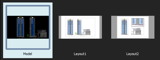
Preview panel
You can reorder the drawing tabs by dragging them.
If more drawings are open than the tabs bar can display:
- Click List All Drawings
 to display a list of all open drawings and select one as needed.
 - Click
 or
or  to move the tabs in the desired direction on the tabs bar.
Asterisks (*) at the end of file names on drawing tabs indicate unsaved drawings.
You can set preferences to show or hide the drawing tabs bar and to select the preview panel display mode.
To add a new drawing tab:
- Click
 next to the last drawing tab.
If no drawing is open, the drawing tabs bar displays the plus icon at the left.
The new drawing uses the default template drawing (similar to the SmartNew command).
To close a drawing tab:
- Do one of the following:
- Click
 on the drawing tab to close.
 - Hover over the drawing tab to close and middle-click.
If the drawing has changed since it was last saved, a prompt asks whether to save the changes.
- Click
To switch to another drawing:
- Click the tab of the drawing to display.
– or –
- Press Ctrl+Tab to cycle through open drawing tabs.
To switch to a specific workspace of a drawing:
- Hover over specific drawing tab.
Preview panels appear below the tab displaying the model and all layout sheets with the active workspace highlighted.
- Select a thumbnail (model or layout sheet) from the preview panel.
The selected workspace displays.
To control drawing tabs with the shortcut menu:
- Right-click a drawing tab or the icon and select an option from the shortcut menu:
- New. Starts a new drawing with a template drawing.
- Open. Opens an existing drawing.
- Save. Saves the drawing with the current file name.
- Save All. Saves all open drawings.
- Save As. Saves the drawing under a different name.
- Close. Closes the active drawing.
- Close All. Exits all open drawings but not the program.
- Close Other Drawings. Closes all open drawings except the active one.
- Make First Tab. Makes the tab where you right-clicked the first drawing tab and makes it the active tab.
- Make Last Tab. Makes the tab where you right-clicked the last drawing tab and makes it the active tab.
- Open Containing Folder. Displays the operating system’s file manager in a separate window pointing to the folder where the file of the selected drawing tab is located.
 Note: If you save or close drawings and one or more drawings have changed since they were last saved, a prompt asks whether to save the changes.
To reorder drawing tabs:
- Select a tab and drag it to a different position along the tabs bar.
To move a drawing tab to the first or last position:
- Right-click a drawing tab and click Make First Tab or Make Last Tab.
To set preferences for drawing tabs:
- Do one of the following:
- Click Tools > Options (or type Options).
In the Options dialog box, click System Options
 .
. - Type SystemOptions.
- Click Tools > Options (or type Options).
- Expand Display > Drawing tabs to set the following:
- Show drawing tabs. Controls the display of drawing tabs at the top of the drawing windows area.
- In Display settings, select one of the following:
- List view. Displays non-graphical lists of workspaces.
- Panel preview. Displays thumbnails for each drawing workspace (model and layout sheets) below tabs (default).
- Click OK.
Access
Command: DrawingTabs
Starting a New Drawing
You can start a drawing from scratch or using a template.
A template is a prototype drawing containing the settings you want for the new drawing. Templates use the .dwt extension. You can also use .dwg files or .dxf files to start with. You can create a template by saving the drawing file with the .dwt extension. To display the new template in the list of available templates, save it under the templates folder.
By default, the drawing is named NONAME_n.dwg.
To start a new drawing with a template:
- Click File > New (or type New).
- Click File > New (or type New).
- Do one of the following:
- On the Quick Access Toolbar, click New.
- In the Application Menu, click New.
- Right-click a drawing file tab and select New.
- Navigate to the .dwt file location.
- Select a .dwt file from the list and click Open.
To start a new drawing without a template:
- Click File > New (or type New).
- In the dialog box, click
 next to Open and select:
- Open with no Template – Imperial: Sets imperial as the units format for the new drawing.
- Open with no Template – Metric: Sets metric as the units format for the new drawing.
Note: These options are available only in the classic Open system file dialog box.
Access
Command: New
Menu: File > New
Keyboard Shortcut: Ctrl + N
Keyboard Shortcut: Ctrl + N
Keyboard Shortcut: Command + N
Ribbon: Sheet > Sheets > Sheet > New Sheet 
Opening a Drawing
You can open drawings stored on your computer or within a network.
The following methods are available:
- Use the Open dialog box
- Drag a drawing from Windows Explorer and drop it in the application window, anywhere outside the graphics area.
Note: Dragging the drawing into the graphics area inserts the drawing content as Block.
- Use the Sheet Set Manager to open a drawing from a drawing sheet set.
Read-only Mode
In a network environment, multiple users can try access drawings at any time. However, only one user can edit a drawing at a time. When you try to open a drawing, the software automatically checks if the drawings are edited by another user and lets you access the drawing in read-only mode.
Note: If you try to save a read-only file, you need to save the file under another name.
Open with Encoding
Encoding standards provide the information that the application needs to display the text from the drawing on the screen. Different languages consist of different sets of characters including alphabetical characters, numbers, and other symbols.
When opening a drawing, you can specify the encoding standard necessary to display the file correctly.
To open a drawing:
- Click File > Open (or type Open).
- Click File > Open (or type Open).
- Do one of the following:
- On the Quick Access Toolbar, click Open.
- In the Application Menu, click Open > Open.
- Right-click a drawing file tab and select Open.
- Navigate to the drawing file location.
- Select a file type from the drop-down list.
- Select a drawing from the list.
Note: Optionally, you can display a thumbnail of the selected drawing in the Preview pane, although not all file formats provide previews.
- Click Open to load the drawing.
If another user is editing the drawing, a message appears. Click Yes to open the file without modifying it.
To open a drawing in read-only mode:
- Click File > Open (or type Open).
- Navigate to your drawing.
- Select a file type from the drop-down list.
- Select a drawing.
Note: Optionally, you can display a thumbnail of the selected drawing in the Preview pane, although not all file formats provide previews.
- Click Open to load the drawing.
- Click the arrow next to Open the and click Open Read-Only to open the file without modifying it.
To open a drawing with encoding:
- Click File > Open (or type Open).
- Navigate to your drawing.
- Select a file type from the drop-down list.
- Select a drawing.
Note: Optionally, you can display a thumbnail of the selected drawing in the Preview pane, although not all file formats provide previews.
- Click the arrow next to Open the and click Open with Encoding.
- In the Open With Encoding dialog box, select the encoding that the application should use.
- Optionally, select Read only to open the file without modifying it.
- Click File > Open (or type Open).
- In Files of type, select a file type.
- In Look in, navigate to your drawing.
- Select a drawing.
The Preview area presents a thumbnail of the selected drawing, although not all file formats provide previews.
- Click Open to load the drawing or click and click Open Read-Only to open the file without modifying it.
If another user is editing the drawing, a message appears. Click Yes to open the file without modifying it.
- Click File > Open (or type Open).
- Select a drawing.
- Click Open to load the drawing or select Open Read-Only from the Open mode list to open the file without modifying it.
If another user is editing the drawing, a message appears. Click Yes to open the file without modifying it.
To control the Preview area display from the classic Open system file dialog box:
Note: This option is available only in the classic Open system file dialog box.
- Click File > Open (or type Open).
- Specify one of the following options:
- Force preview pane. Enables the drawing content preview in the Preview pane regardless of the File Explorer settings.
- Keep Explorer settings. Displays the Preview pane only if it is enabled in the File Explorer settings.
Note: The setting takes effect only when you display the Open dialog box again.
Access
Command: Open
Menu: File > Open
Keyboard Shortcut: Ctrl + O
Keyboard Shortcut: Ctrl + O
Keyboard Shortcut: Command + O
Saving Drawings
You can save drawings for later use.
This section discusses:
- About Saving Drawings
- Saving a Drawing
- Saving the Drawing under a Different Name
- Saving All Open Drawings
About Saving Drawings
You can save drawings for later use. Additionally, you can save and backup drawings automatically.
Save your drawings frequently to avoid losing your work in case of power loss, inappropriate system shut-down, or other technical event.
The default file extension for drawing files is .dwg. Additionally, you can also save a drawing to a Drawing Exchange Format (.dxf), as a Drawing Template File (.dwt), or in another format available in the file type drop-down list from the Save As dialog box.
You can change the default file format in the Options dialog box.
Every time you manually save a .dwg, the software automatically creates a backup file of the previous version of the drawing file. By default, the drawing backup file is saved in the same folder as the drawing (.dwg file) and has the same name as the drawing but with a .bak extension. To revert to the previous version, rename the .bak file with a different name and a .dwg file extension.
Commands for Saving Drawings
The following commands let you save your drawings. Choose the command suitable to what you want to accomplish.
- Save. Use the Save command to save the drawing with the current file name or to a specified name if the drawing is unnamed.
- SaveAs. Use the SaveAs command to save an unnamed drawing with a file name or to rename the current drawing.
- SaveAll. Use the SaveAll command to save the drawing in the current window and all other open drawings.
Saving a Drawing
Use the Save command to save the drawing with the current file name or to a specified name if the drawing is unnamed.
To save a drawing:
- Click File > Save (or type Save).
The drawing is saved under the location, name, and file type specified when it was opened.
If the drawing is unnamed, the Save As dialog box opens so you can set the location, name, and file type.
Access
Command: Save
Menu: File > Save
Keyboard Shortcut: Ctrl + S
Keyboard Shortcut: Ctrl + S
Keyboard Shortcut: Command + S
Saving the Drawing under a Different Name
After you have saved your drawing for the first time, you can save it under a different name.
Use the SaveAs command to save an unnamed drawing with a specified file name and format or to rename the current drawing. Additionally, you can specify a different file format.
To save a drawing under a different name:
- Click File > Save As (or type SaveAs).
- In the Save As dialog box, navigate to the folder where you want to store the drawing file.
- Specify the file details:
- Select a file type from the drop-down list.
- Type a name for the file.
- Click Save.
- Click File > Save As (or type SaveAs).
- In the dialog box, specify the file details:
- Navigate to the folder where you want to store the drawing file.
- Save As: Type a name for the file.
- Files of Type: Select a file type.
- Click Save.
Access
Command: SaveAs
Menu: File > Save As
Keyboard Shortcut: Ctrl + Shift + S
Saving All Open Drawings
Use the SaveAll command to save the drawing in the current window and all other open drawings.
To save all open drawings:
- Type SaveAll.
Opened drawings are saved under the location, name, and file type specified when they were opened.
If a drawing is unnamed, the Save As dialog box opens so you can set the location, name, and file type.
Access
Command: SaveAll
Viewing and Editing Drawing File Properties
You can view and edit the standard properties of the current drawing file and you can create custom properties for the file.
Standard drawing properties include details such as author name, title, subject, keywords, and comments that describe the drawing’s topic or contents.
You can also define custom properties for the drawing.
To view and edit the standard properties of the current drawing:
- Click File > Properties (or type DrawingProperties).
- In the dialog box, on the Summary tab, view the properties and type or edit values as needed.
- Editable fields include author, keywords, comments, title, and subject.
- The Statistics area informs about creation date and last saved date of the drawing file as well as the name of the user who last saved the file.
- Click OK.
To view and edit the custom properties of the current drawing:
- Click File > Properties (or type DrawingProperties).
- In the dialog box, click the Custom tab.
- In the Name column, select a box.
- In the list, select a property name.
- In the Value column, the property value is displayed.
- Type a value or edit the value in the box as needed.
- Click OK.
To add custom properties to the current drawing:
- Click File > Properties (or type DrawingProperties).
- In the dialog box, click the Custom tab.
- Click Edit list.
- In the dialog box, add a property name to the list.
- Click OK.
- At the bottom of the table, select the empty row.
- In the Name column box, type the name of the new custom property, or select its name from the list.
- In the corresponding Value box, type a value for the custom property.
- Click OK.
- The property names you added to the list are stored in the user’s profile to use them in other drawing files.
To remove custom properties from the drawing:
- Click File > Properties (or type DrawingProperties).
- In the dialog box, click the Custom tab.
- Highlight a row in the custom properties list.
- Click Delete.
- The custom property and its value is deleted in the drawing file.
- Click OK.
Standard drawing file properties are displayed in the names list in the Field dialog box.
Access
Command: DrawingProperties
Menu: File > Properties
Closing a Drawing
Use the Close command to close a drawing. The software remains open.
To close a drawing:
- Click File > Close (or type Close).
If the drawing has changed since it was last saved, a prompt asks whether to save the changes.
- Click Yes to save the changes or No to discard them.
If the drawing is unnamed, the Save As dialog box opens so you can set the location, name, and file type.
Alternatively, hover over the drawing tab to close and middle-click twice.
Access
Command: Close
Menu: File > Close
Keyboard Shortcut: Ctrl + F4
Keyboard Shortcut: Ctrl + F4
Closing All Open Drawings
Use the CloseAll command to close all open drawings.
To close all open drawings:
- Click Window > Close all (or type CloseAll).
- If one or more drawings have changed since they were last saved, a prompt asks whether to save the changes for each changed drawing.
- Click Yes to save the changes or No to discard them.
- If a drawing is unnamed, the Save As dialog box opens so you can set the location, name, and file type.
Access
Command: CloseAll
Menu: Window > Close all
Exiting
Be sure to end every working session safely by executing the Exit command.
To exit:
- Click File > Exit (or type Exit).
If one or more drawings have changed since they were last saved, a prompt asks whether to save the changes for each changed drawing.
If a drawing is unnamed, the Save File dialog box opens so you can set the location, name, and file type.
After saving the open drawings, the current working session ends.
- Click Exit on the application menu (or type Exit).
If one or more drawings have changed since they were last saved, a prompt asks whether to save the changes for each changed drawing.
If a drawing is unnamed, the Save File dialog box opens so you can set the location, name, and file type.
After saving the open drawings, the current working session ends.
Access
Command: Exit
Menu: File > Exit
Menu: File > Exit
Menu: Application menu > Quit
Keyboard Shortcut: Ctrl + Q or Alt + F4
Keyboard Shortcut: Ctrl + Q or Alt + F4
Keyboard Shortcut: Command + Q
Exporting and Importing
Use export and import features to:
- Save a drawing or the current view of a drawing to vector or raster image formats including .dxf, .sat (ACIS), .pdf, .bmp, .png, .jpg, and .svg.
- Load drawing files created by other applications or CAD programs of formats .dwg, .dxf, and .sat (ACIS).
Instead of using an import command, use the InsertBlock command to insert .dwg and .dxf drawings at a specified insertion point, rotation angle, and scale factor. You can also attach drawing files (.dwg) or raster image files (.bmp, .png, .jpg, and .png, for example) to your drawing using the References, AttachDrawing, or AttachImage commands.
Exporting
Use the Export command to save a file to the following formats:
- BMP (Bitmap)
- EMF (Windows Enhanced Metafile)
- EPS (Encapsulated PostScript)
- JPEG (Joint Photographic Experts Group standard, a bitmapped image format)
- PDF (Portable Document Format)
- PNG (Portable Network Graphics, a bitmapped image format)
- SLD (Slide)
- STL (Stereolithography File)
- SVG (Scalable Vector Graphics format)
- TIF (Tagged Image File)
- WMF (Windows Metafile)
- STEP (Standard for the Exchange of Product model data)
- IGES (Initial Graphics Exchange Specification)
The output contains the visible section (current view) of the active drawing.
To export:
- Click File > Export > Export (or type Export).
- In the dialog box, specify the following:
- Save in: Navigate to the folder where you want to store the file.
- File name: Type a name for the file.
- Save as type: Select a file type for exporting.
- Click Save.
Access
Command: Export
Menu: File > Export > Export
Exporting DXF Files
Use the ExportDXF command to export the current drawing as a DXF (Drawing Exchange Format) file containing the complete database information for all entities and objects in a CAD drawing.
DXF files are used to interchange drawing data with other applications.
DXF files can be either a standard ASCII text file or a binary file. Typically the term DXF file refers to ASCII DXF files which are more common than binary DXF files. Generally speaking, binary DXF files are about a fourth smaller than ASCII DXF files and reads and write about five times faster.
To export to a DXF file:
- Type ExportDXF.
- In the dialog box, specify the following:
- Save in: Navigate to the folder where you want to store the file.
- File name: Type a name for the file.
- Save as type: Select a .dxf type.
- Click Save.
Note: The DXF format varies from different releases. Also keep in mind, that some programs are not able to binary DXF files.
Access
Command: ExportDXF
Exporting ACIS SAT Files
Use the ExportSAT command to export selected Regions or solid modeling entities from the current drawing into an .sat file.
To export to an ACIS SAT file:
- Type ExportSAT.
- Select all entities to export, and press Enter.
- In the dialog box, specify the following:
- Save in: Navigate to the folder where you want to store the file.
- File name: Type a name for the file.
- Click Save.
Access
Command: ExportSAT
Creating a PDF File from a Drawing
Use the ExportPDF command to save the current view to a PDF (Portable Document Format) file.
Note: The PDF file that the ExportPDF command creates is a preview of the current view. The command ignores the drawing scale.
To create a PDF file from a drawing:
- Click File > Export > PDF Export (or type ExportPDF).
- In the dialog box, type the Name of the PDF file to create. Click Browse to browse for a folder and name.
- In Sheets, select the Sheets to export. Each Sheet will be a separate page in the PDF file.
Note: Click Clear all to cancel the selections or Select all to select all Sheets.
- In Paper Size, select one of the following:
- Standard to select a standard format from the list of paper sizes.
- Custom to specify the Width and Height of a custom format using the Units you select.
- Margins. Lets you specify the width of the top, bottom, left, and right margins that cannot be printed upon.
- In Margins you can specify the width of the top, bottom, left, and right margins that cannot be printed upon.
- Specify Options for the PDF file generation:
- Use print style table: Maps layer colors or entity colors to the specifications defined in a PrintStyle table file (*.ctb, or *.stb). From the list of PrintStyle table files, select the file to apply. For more information on PrintStyles see Managing PrintStyle Tables.
- Use layers in PDF file (PDF v1.5 or higher): Creates layers in the PDF file according to the layers in the drawing. Increases the PDF file size.
- Custom bitmap resolution: Gradient fills and shaded objects and Viewports in the drawing are output with the dots per inch resolution specified in DPI (max. 600 DPI). The file size increases if you set a higher resolution. If you intend to print the PDF file to a specific output device, you may want to specify a resolution that matches the printer’s resolution.
-
True Type fonts: Specifies how to handle annotations using TrueType fonts:
- Embedded: Embeds the TrueType fonts used in the drawing’s annotations in the output file. Increases the PDF file size.
- Optimized: Specifies whether to use True Type font-related optimization when creating the PDF file. This may influence the output performance, but reduces the file size.
- As geometry: Converts annotations that use TrueType fonts into outlined geometry in the PDF file.
- Print transparency: Determines whether to take into account entities transparency when creating the PDF file.
- In Document properties, specify information about the document:
- Author: Type the name of the person who created the document.
- Keywords: Type keywords to associate them with the PDF document during a search. Keywords are useful for narrowing searches.
- Title: Type the document’s title. Various search engines use the title to describe the document in their search results lists.
- Subject: Type the subject of the document.
- Creator (generated automatically): Reports the source application of the PDF file.
- Producer (generated automatically): Reports the converter engine used by the application to create the PDF file.
In the same section, select or clear:
- Save to PDF document properties data: Enhances the exported PDF file with the specified document properties metadata.
- Save back to drawing properties data: Stores the specified metadata in the Drawings Properties of the drawing file. Existing data may be overwritten.
- Click OK.
Access
Command: ExportPDF
Menu: File > Export > PDF Export
Creating a Bitmap File from a Drawing
Use the ExportBMP command to save the current view to a bitmap (BMP) file.
To create a BMP file from a drawing:
- Type ExportBMP.
- In the dialog box, navigate to the folder where you want to store the file.
- In File name, type a name for the file.
- Click Save.
Access
Command: ExportBMP
Creating a JPEG File from a Drawing
Use the ExportJPG command to save the current view to a JPEG file, a raster image file.
To create a JPEG file from a drawing:
- Type ExportJPG.
- In the dialog box, specify the following:
- Save in: Navigate to the folder where you want to store the file.
- File name: Type a name for the file.
- Click Save.
Access
Command: ExportJPG
Creating a PNG File from a Drawing
Use the ExportPNG command to save the current view to a PNG file (Portable Network Graphics, a bitmapped image format).
To create a PNG file from a drawing:
- Type ExportPNG.
- In the dialog box, specify the following:
- Save in: Navigate to the folder where you want to store the file.
- File name: Type a name for the file.
- Click Save.
Access
Command: ExportPNG
Creating an EMF File from a Drawing
[Windows® version only]
[Windows® version only]
Use the ExportEMF command to save the current view to an EMF file (Windows Enhanced Metafile, a vector and raster image format).
To create an EMF file from a drawing:
- Type ExportEMF.
- In the dialog box, specify the following:
- Save in: Navigate to the folder where you want to store the file.
- File name: Type a name for the file.
- Click Save.
Access
Command: ExportEMF
Creating a WMF File from a Drawing
[Windows® version only]
[Windows® version only]
Use the ExportWMF command to save the current view to a WMF file (Windows Metafile, a vector and raster image format).
To create a WMF file from a drawing:
- Type ExportWMF.
- In the dialog box, specify the following:
- Save in: Navigate to the folder where you want to store the file.
- File name: Type a name for the file.
- Click Save.
Access
Command: ExportWMF
Creating an SVG File from a Drawing
Use the ExportSVG command to save the current view to an SVG file (Scalable Vector Graphics Format).
To create an SVG file from a drawing:
- Type ExportSVG.
- In the dialog box, specify the following:
- Save in: Navigate to the folder where you want to store the file.
- File name: Type a name for the file.
- Click Save.
Access
Command: ExportSVG
Creating an EPS File from a Drawing
Use the ExportEPS command to save the current view to an EPS file (Encapsulated PostScript file). An EPS file specifies text and other drawing entities as vectors.
To create an EPS file from a drawing:
- Type ExportEPS at the command prompt.
- In the dialog box, specify the following:
- Save in: Navigate to the folder where you want to store the file.
- File name: Type a name for the file.
- Click Save.
Access
Command: ExportEPS
Creating a Stereolithography File from a Drawing
Use the ExportSTL command to save 3D solid objects to stereolithography (STL) files.
To create an STL file from a drawing:
- Type ExportSTL at the command prompt.
- Specify 3D solid objects to output.
- Specify whether to create a binary file or an ASCII text file.
- In the dialog box, specify:
- Save in: Navigate to the folder where you want to store the file.
- File name: Type a name for the file.
- Click Save.
Use the Union command to unify separate 3D solid objects before exporting to STL files.
Access
Command: ExportSTL
Importing a Stereolithography File
Use the ImportSTL command to import stereolithography files (STL) and insert the contained geometry as ACIS solid objects into the drawing.
To import STL files:
- Type ImportSTL at the command prompt.
The dialog box displays with the file type set to .stl.
- Navigate to the STL file to import and click Open.
Access
Command: ImportSTL
Importing a Stereolithography File As Mesh
Use the ImportSTLAsMesh command to import stereolithography files (STL) and insert the contained geometry as subdivision mesh objects (SubDMeshes) into the drawing.
The command is similar to the ImporSTL command but the result is a different object type.
When selected, the Properties palette shows the M vertex count and the N vertex count for the SubDMesh object in the Mesh section.
To import STL files:
- Type ImportSTLAsMesh at the command prompt.
The dialog box displays with file type set to .stl.
- Navigate to the STL file to import and click Open.
If you explode a SubDMesh using the Explode command, it is converted into three- or four-sided surfaces in space named Faces.
Access
Command: ImportSTLAsMesh
Importing DXF Files
Use the ImportDXF command to read a DXF file and open it in a separate drawing window. A DXF file (Drawing Exchange File) is a standard ASCII text file containing the database information for the entities and objects in a CAD drawing.
It is also possible to open a DXF file using the Open command or to insert a DXF file as a block using the InsertBlock command.
To import DXF files:
- Type ImportDXF.
- In the dialog box, navigate to the DXF file to import.
- Click Open to load the DXF file or click and click Open Read-Only to open the file without modifying it.
- If you try to save a read-only file with changes, an error message prompts you to save the file under another name.
Access
Command: ImportDXF
Importing DWF Files
Use the ImportDWF command to insert a DWF file into a drawing. If the DWF file is password protected, you must enter the password.
To insert a DWF file:
- Type ImportDWF at the command prompt.
The dialog box displays with Files of type set to .dwf.
- Navigate to the DWF file to insert and click Open.
- If the DWF file is password protected, type the password at the prompt.
- Type a value for Width and Height.
- Specify whether to preserve color indices when importing the DWF file.
- Select a Sheet to import or select All to import all Sheets.
- Specify whether to import a 3D DWF file.
Access
Command: ImportDWF
Importing ACIS SAT Files
Use the ImportSAT command to read a .sat file and insert the included ACIS solid entities into the current drawing.
To import ACIS SAT files:
- Type ImportSAT.
- Navigate to the ACIS file to import and click Open.
The command supports the import of ACIS SAT files from version 1.0.5 to 27.
Access
Command: ImportSAT
Importing PDF Files as Blocks
Use the ImportPDF command to insert content from Adobe® PDF files as Blocks into your drawings. You can insert all or selected pages from multiple page PDF documents.
If the PDF file contains vectors, they are converted to drawing entities such as lines, circles, ellipses, and splines. Text lines are converted to text entities using the same fonts (presupposed the fonts embedded in the PDF file are available on your system). Raster graphics in a PDF file are stored as image files on the hard disk which are then referenced as images in the drawing where you import the PDF file.
You can also convert large number of files automatically using the batch processing feature.
This topic discusses
- how to import PDF files as Blocks,
- how to set preferences for the convertion of PDF files to drawing Blocks, and
- how to convert PDF files to DXF files in a batch operation.
To import PDF files as Blocks:
- Click Insert > PDF Import (or type ImportPDF).
- Type ImportPDF.
- In the dialog box, under Mode, select Insert as Block.
- Under PDF File, click Browse.
- In the dialog box, select a PDF file, then click OpenOK.
In the dialog box, under PDF File:
- File Path. displays the complete path and name of the PDF file you selected.
-
Reference Path. displays the complete path to the image files referenced in the Block you create from the PDF file.
Click Browse to select a different folder for referenced files.
- If the PDF file contains multiple pages, select the pages to insert as Blocks from the icons list:
- Click an icon to select a single page.
- Click an icon and, while you hold down the Shift key, click another icon to specify a range of continuous pages.
- Hold down the Ctrl key, and click several icons to specify multiple non-continuous pages.
- Under Scale, type a scale factor, or select Specify later to specify the scaling on screen after closing the dialog box.
- Under Rotation, for Angle, type a value or select Specify later to set the rotation angle in the graphics area during insertion.
- Under Scale & Rotation specify:
- Under Scale, type a scale factor, or select Specify later to specify the scaling on screen after closing the dialog box.
- Under Rotation, for Angle, type a value or select Specify later to set the rotation angle in the graphics area during insertion.
- Click Options to set preferences for the convertion of PDF files to Block insertions (see below for details).
- Click OK
 .
. - In the graphics area, specify the insertion point(s) for the Blocks originating from the specified PDF file pages.
- Specify scale factor and rotation angle if needed.
Note: To break the Block you inserted into its component entities, use the Explode command.
To set preferences for the convertion of PDF files to drawing Blocks:
- Click Insert > PDF Import (or type ImportPDF).
- Type ImportPDF.
- Click Options.
- In the dialog box, activate or deactivate preferences for the conversion of PDF files:
- Intelligent recognition. Specifies whether the converter attempts to recognize objects in the PDF file that represent circles, arcs, or ellipses, to create Circles, Arcs or Ellipses in the Block that is inserted into the drawing. Otherwise, these objects are converted to Splines. Note, that intelligent recognition enabled is more time consuming.
- Ignore Image objects. Specifies whether raster images are converted. Raster images are referenced in the Block inserted into the drawing as externally stored files. Use the Reference command to manage Image References in the drawing.
- Ignore Path objects. Specifies whether vectors are converted and inserted into the drawing. Vectors (such as lines, arcs, and splines) become part of the Block that is inserted into the drawing.
- TrueType text. Specifies whether text entities that use TrueType fonts are converted and inserted into the drawing. If possible, drawing text uses the same fonts as PDF text. If a corresponding font is not available on the system, the active TextStyle is used in the drawing.
- Ignore white fills. Specifies whether closed boundaries contained within the geometry of the converted file are filled white by a solid hatch.
- Maintain LineStyle. Specifies whether the line style properties of the imported entities is retained or ignored.
- Maintain LineWeight. Specifies whether the lineweight properties of the imported entities is retained or ignored.
- Use PDF Layers. Specifies whether layers are created from the layers stored in the PDF file. If the PDF file contains no layers, entity layers are created.
- Create entity layers. Specifies whether layers are created according to the entities imported from the PDF file. For example, PDF_Text, PDF_Images.
- Use current layer. Specifies whether all specified PDF entities are imported to the current layer.
- Click OK or Cancel.
The settings from the Options dialog box are maintained until you change them.
- Close the dialog box.
To convert PDF files to DXF drawing files in a batch processing operation:
- Click Insert > PDF Import (or type ImportPDF).
- In the dialog box, under Mode, select Batch Processing.
- In PDF Files:
- Click Browse to specify a Source Path that contains the PDF files to convert to DXF files.
- Click Browse to specify a Destination Path where the resulting DXF files and their dependent referenced images are stored.
- In the Files list, activate the PDF files to convert during batch processing.
Click Select all to mark all PDF files in the list.
- Click OK to start batch processing of the specified files.
A progress bar displays the conversion progress.
Access
Command: ImportPDF
Menu: Insert > PDF Import
Importing DGN files as Blocks
Use the ImportDGN command to insert content from DGN files (DesiGN files) as Blocks into drawings. Files of type .dgn originate from MicroStation® or other CAD software. Supported versions include DGN V7 and V8.
If the DGN file contains multiple Design Models, you can select the model to insert.
You can also convert large numbers of files automatically using the batch processing feature.
This topic discusses how to:
- Import DGN files as Blocks.
- Set preferences for converting DGN files to drawing Blocks.
- Convert DGN files to DWG files in a batch operation.
To import DGN files as Blocks:
- Click Insert > DGN Import (or type ImportDGN).
- Type ImportDGN at the command prompt.
- In the DGN Import dialog box, under Mode, select Insert as Block.
- Under DGN File, click Browse.
- In the Open dialog box, select a DGN file, and click Open.
In the DGN Import dialog box, information displays under DGN file:
- Name. Displays the complete path and name of the DGN file you selected.
- Path. Displays the complete path to the DGN files referenced in the Block you create from the DGN file.
- If the DGN file contains multiple Design Models, select the model to insert as a Block.
In DGN files, a drawing can be separated into Design Models which are individual workspaces where design geometry is defined.
- In Conversion units, specify whether unit conversion uses Master units or Sub units as its base. The measurement units defined in the DGN file appear in brackets.
Master units and sub units express a relationship between applicable measurement units such as feet and inches or meters and millimeters. Sub units cannot be larger than master units. The selected units are converted one-to-one into drawing units.
- Under Scale, type a scale factor, or select Specify later to specify the scaling in the graphics area after you close the dialog box.
The initial scale factor is set according to the ratio of units (master unit or sub unit) specified in the DGN file to the units used in the current drawing.
- Under Rotation, for Angle, type a value or select Specify later to set the rotation angle in the graphics area during insertion.
- Click Options to set preferences for the convertion of DGN files to Block insertions (see below).
- Click OK.
- In the graphics area, specify the insertion point for Blocks originating from the specified DGN file.
- Specify scale factor and rotation angle, if needed.
Note: To break a Block into its component entities, use the Explode command.
To set preferences for converting DGN files to drawing Blocks:
- Click Insert > DGN Import (or type ImportDGN).
- Type ImportDGN at the command prompt.
- Click Options.
- In the dialog box, specify whether to Explode text node to text elements.
If selected, text node entities in DGN files are converted to SimpleNotes, otherwise they are converted to Notes.
Text nodes are multiline text entities similar to Notes.
- Click Close.
To convert DGN files to DWG files in a batch operation:
- Click Insert > DGN Import (or type ImportDGN).
- Type ImportDGN at the command prompt.
- In the dialog box, under Mode, select Batch Processing.
- In the dialog box, select Batch Processing.
- Specify whether unit conversion uses Master units or Sub units as its base. The measurement units defined in the DGN file appear in brackets.
Master units and sub units express a relationship between applicable measurement units such as feet and inches or meters and millimeters. Sub units cannot be larger than master units. The selected units are converted one-to-one into drawing units.
- In DGN files:
- Click Browse to specify a Source Path that contains the DGN files to convert to DWG files.
- Click Browse to specify a Destination Path where the resulting DWG files are stored.
- In DGN files:
- Click Source to specify a Source Path that contains the DGN files to convert to DWG files.
- Click Destination to specify a Destination Path where the resulting DWG files are stored.
- In the Files list, select the DGN files to convert during batch processing.
- Click OK to start batch processing of the specified files.
- Click Start to start batch processing of the specified files.
Access
Command: ImportDGN
Menu: Insert > DGN Import
Opening and Saving ESRI Shape (SHP) Files
Geographic information system (GIS) software products use ESRI Shape files (.shp) to store graphical information (such as parcels of land, streets, railway lines, areas with buildings, distribution networks, green areas, forests, rivers, lakes, and so on).
The Shape file format is a vector data format developed by Environmental Systems Research Institute, Inc. (ESRI), which is used as a GIS data exchange format.
Unlike drawing file formats (such as DXF or DWG), Shape files do not contain complete graphical information.
A complete set of the data that makes up a map, landscape profile, or other geographic plan is grouped in a directory where Shape files present geometric vector data. Other file types store attributes and properties.
The entities stored in a single Shape file are always of one type: points, lines, or polygons (which represent geometric information). In Shape files, reference data are associated to the primitive entities.
.shp files are associated with a database file (.dbf) and an index file (.shx), which exist in the same folder and with the same name. In GIS projects, other file types are associated with the .shp file.
When opening Shape files:
- The application detects the type of information to import (points, lines, or polygons) and presents only entities for that type in the drawing. You cannot examine attributes associated with the geometric objects.
Note: Open a .shp file only if a .dbf and .shx file exist in the same folder and with the same name.
When saving Shape files:
- You can save back Shape files. You can change the position and location of geometry in such files, but you cannot insert new geometry with attributes into the files you write.
- Use SaveAs to save a Shape file under a different name. This creates an associated .dbf and .shx file with the same name.
- You can save drawings as Shape files using SaveAs. Make sure the Shape file contains only entities of one and the same type (points, lines, or polygons). However, this only makes sense if you have post-processing software that can handle the exported data.
Note: Do not confuse the Shape file format with the font source format, which shares the .shp extension used in CAD software.
To open ESRI Shape files:
- Click File > Open (or type Open).
- In the dialog box, from the list of file types, select ESRI Shape file (*.shp).
- Navigate to the .shp file and select it.
- Click Open to load the drawing or click
 and click Open Read-Only to open the file without modifying it.
To save ESRI Shape files under a different name:
- Click File > Save As (or type SaveAs).
- In the dialog box, specify:
- In Save as type, select ESRI Shape file (*.shp).
- In File name, type a name for the file.
- Navigate to where you want to store the file.
- Click Save.
Creating Slide Files from Drawings
Use the ExportSLD command to save the current view of the drawing to a slide file (.sld).
You can view slide files with the ViewSlide command.
Use the LoadScript command to display slide shows to present views of drawings.
To create a slide file from a drawing:
- Type ExportSLD at the command prompt.
- In the dialog box:
- Navigate to the folder where you want to store the file.
- For File name, type a name.
- In Save as type, select Slide (SLD).
- Click Save.
To enhance the quality of curved entities in slides, use the DisplayQuality command.
Access
Command: ExportSLD
Viewing Slide Files
Use the ViewSlide command to view slide files (.sld). You can create slide files with the ExportSLD command.
The slide you view disappears when the drawing refreshes, for example when you use another command.
To view slide files:
- Type ViewSlide at the command prompt.
- In the dialog box, navigate to the slide (.sld) file to view.
- Click Open.
- The slide displays.
- Click View > Refresh (or type Refresh) to clear the screen from the slide.
Use the LoadScript command to display slide shows to present sequences of drawing views.
Access
Command: ViewSlide
Working with BIM Files
Building Information Modeling (BIM) is a workflow that lets you create and manage 3D model information during the lifecycle of a project.
The following file types are supported:
- .ifc files
- .rvt files
You can import BIM files, such as .ifc and .rvt files to your project and create the necessary documentation based on the BIM model. Various CAD features let you access information about the model and annotate the drawings.
The BIM Navigator palette groups all tools necessary for working with BIM models and drawings.
The basic workflow for working with BIM models includes the following steps:
-
Import the BIM file contaning the model.
The current .dwg file stores a link to the imported BIM file. See Importing BIM Files.
-
Work with the BIM model in the graphics area.
You can import BIM files, such as .ifc and .rvt files to your project and load the BIM model in the graphics area.
- Display BIM entities properties in the Properties palette.
- Move the BIM file if required.
- Use filters to control the display of BIM entities in the graphic area based on criteria, such as: Category, Predefined Type, or Entity Type.
- Map BIM material names that exist in the loaded BIM file to the materials available in the BIM Materials Styles Library.
-
Extract data from BIM entities to .csv files.
You can extract information from a set of entities using the Data Extraction wizard. See Extracting Data to Tables and Files.
-
Specify where to cut the model to create drawings. See Creating BIM Drawings.
- Annotate the drawings using annotation tools.
- Use hatches and line weights to improve the display of entities in the drawings.
As the project evolves, new versions of BIM models may be received. Reload the BIM file to update the software with the current version of the BIM model. You must refresh the drawings so that all of the drawings reflect the current state of the BIM. See Managing BIM Drawings. -
Place the drawings on the sheets.
When you place a drawing on a sheet, the software automatically places drawing callout symbol and drawing title under the drawing. See Placing Drawings on Sheets.
Before placing drawings on a sheet, open a sheet tab and set the sheet size options.
This chapter discusses:
- Importing BIM Files
- Managing BIM Files
- Working with BIM Models
- Working with BIM Drawings
- Working with BIM Materials
- Using the BIM Navigator
Importing BIM Files
You can import .ifc and .rvt files and display their content in the current .dwg file. The current .dwg file stores a link to the imported BIM Files.
Note: Make sure to save the drawing file before importing .ifc and .rvt files.
To import a BIM file:
- Do one of the following:
- In the BIM Navigator palette, click Import.
- Type BIMImport.
- Navigate to the file to import and click Open.
The BIM Navigator displays the imported file in the BIM Files list.
Click  to insert the BIM file content in the graphics area.
Access
BIM Navigator palette: click Import.
Managing BIM Files
The BIM Files category of the BIM navigator palette provides tools for managing BIM files that you imported into the drawing.
These file types are listed in the tree view:
- .ifc files
- .rvt files
You can:
- Import BIM files.
When importing BIM files, the curent drawing stores a link to the imported BIM file.
- Control the access to a BIM file.
You can lock a BIM file to prevent it from editing. Unlocking the BIM file displays the file content in the graphics area. Additionally, the Entities category lists the BIM entities in a tree view.
- Control the visibility of the entities.
You can show or hide all entities of the BIM files that you imported in the current drawing.
- Manage the link with the BIM file.
When working on a project, you might need to update some BIM files. You must reload the BIM file to display its content in the form in which it was most recently saved.
To unlock a BIM file:
- In the BIM Navigator palette, click BIM Files.
- Select the file to load in the graphics area and click Unlock.
The BIM entities are displayed in the graphics area.
Note: To lock the BIM file, click Lock.
To unload a BIM file:
- In the BIM Navigator palette, select BIM Files.
- In the imported files list, right-click the file to unload and click Unload.
The content of the selected file is no longer visible in the graphics area, but the link to the file is maintained. To redisplay an unloaded BIM file, specify the Reload from option.
To reload a BIM file:
When working on a project, you might need to update some BIM files. You must reload the BIM file to display its content in the form in which it was most recently saved.
- In the BIM Navigator palette, select BIM Files.
- In the imported files list, right-click the file to reload and click Reload.
The content from the BIM file is displayed in its latest state.
To reset the path to a BIM file:
- In the BIM Navigator palette, select BIM Files.
- In the imported files list, right-click the file to reload and click Reload from.
- Navigate to the new location and select the BIM file, then click Open.
To delete a BIM file:
- In the BIM Navigator palette, select BIM Files.
- In the imported files list, right-click the file to delete and select Delete from the context menu.
The file is deleted from the imported files list. The content of the selected file is no longer visible in the graphics area.
Access
Command: BIMNavigator
Ribbon: BIM > Palettes > Navigator
Working with BIM Models
You can import BIM files, such as .ifc and .rvt files to your project and load the BIM model in the graphics area.
This section discusses:
- Viewing BIM Entities Properties
- Moving BIM Files
- Filtering BIM Entities
- Controlling the BIM Entities Display
Viewing BIM Entities Properties
Use the Properties palette to view the parameters that define the properties of BIM entities.
When you select other categories of entities and BIM entities, you can use the filter drop-down list to view only the properties for a specific category. For BIM entities, the filter drop-down displays BIM Entity.
To view BIM entities properties:
- Do one of the following:
- On the menu, click Modify > Properties.
- On the ribbon, click BIM > Palettes > Properties.
- Type Properties.
- In the graphics area, select one or more entities of the BIM model.
The Properties palette displays the BIM entity properties in read-only mode.
Access
Command: Properties
Moving the BIM File Content
Use the BIMMove command to reposition all entities of the BIM file within the coordinate system without changing their orientation or size.
To move BIM file content:
- Type BIMMove at the command prompt.
- In the graphics area, specify one or more BIM entities and press Enter to complete your selection.
- Specify a base point and target point to move the BIM entities by the specified amount.
The BIM entities moves as specified.
Access
Command: BIMMove
Filtering BIM Entities
You can use filters to control the display of BIM entities in the graphic area and in the Entities tree view, based on criteria, such as: Name, Predefined Type, or Entity Type.
The Filter category of the BIM Navigator lets you define and manage filters.
A filter defines rules based on categories and properties.
You can:
- Create complex selection filters, using relational operators.
- Apply selection filters transparently during the execution of modification commands.
- Save and apply named filters
After you select BIM entities based on the filter, you can move the entities using the BIMMove command.
Note: The filter does not create a selection set. It defines criteria to apply on a selection set.
To create and apply selection filters:
- On the BIM Navigator palette, click Filters.
- In Entities, under Criteria, do the following settings:
- Specify a property.
- Specify a relational operator (== or !=).
- Specify a value.
- Click Add
 to add the item to the criteria list.
You can delete criteria.
- Repeat steps 2 and 3 as needed.
- In Group by, select one or more criteria if needed. Click Add to add the item to the list.
To delete a criteria, click
 .
. - In Sort, specify the property according to which to filter the BIM entities.
- Select an ascending or a descending order.
- Do one of the following:
- To save the filter under the same name: click Save.
- To save the filter under a different name: click Save As.
- In the Name Filter dialog box, specify the name and click OK.
The filter is now active.
Note: The Filter drop-down list displays all available filters.
To modify a filter criteria:
- On the BIM Navigator palette, click Filters.
- From the drop-down list, specify the filter to modify.
- In Entities, use options as needed:
- Add or delete criteria
- Add or delete grouping criteria
- Change the order
- Do one of the following:
- To save the filter under the same name: click Save.
- To save the filter under a different name: click Save As.
To delete a filter:
- On the BIM Navigator palette, click Filters.
- From the drop-down list, specify the filter.
- Click
 and specify Delete from the context menu.
To rename a filter:
- On the BIM Navigator palette, click Filters.
- From the drop-down list, specify the filter.
- Click and specify Rename from the context menu.
Controlling the BIM Entities Display
The Entities category displays the entities of each imported BIM file in a tree view grouped according to their category and type. All categories of named entities contained in the BIM file are taken into account.
Note: The Entities category displays only after you unlock the BIM file.
The tree view lets you browse the BIM file entities. Clicking an entity or a category of entities in the tree view selects the entities in the graphics area. Additionally, double-clicking a file in the tree view selects all entities of the file in the graphics area.
To display the categories in the BIM file tree view, click the ( ) sign in front of a BIM file.
You can show or hide entities and categories of entities individually or according to a category.
You can:
- Display or hide one entity
- Display or hide certain entities
- Display or hide entities of one file
- Display or hide a category of entities
- Display or hide entities of a floor
To expand or collapse all categories:
- On the BIM Navigator palette, click Entities.
- Do one of the following:
- Click Expand
 to expand all categories from all imported BIM files.
 - Click Colapse
 to colapse all categories from all imported BIM files.
- Click Expand
To show or hide all entities:
- On the BIM Navigator palette, click Entities.
- Click
 to show or hide all entities from all imported BIM files in the graphics area.
You can also show these categories in the BIM file tree view by clicking the sign () sign in front of a BIM file (which expands the categories list).
To show or hide the entities of a category:
- On the BIM Navigator palette, click Entities.
- In the tree view, click the icon in the corresponding Show cell.
A green dot
 means show. A gray dot
 means hide.
Working with BIM Drawings
You can create plans, sections, and elevations from the BIM model:
This section discusses:
Creating Drawings from the BIM Model
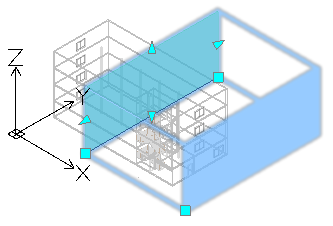
Use the BIMSection command to automatically create the following drawings from the BIM model:
- Plans
- Sections
- Elevations
Each drawing type has a specific graphical display and appears in a different branch in the BIM Navigator.
All drawing types are defined by a drawing volume clipping box which is specified by two points defining the drawing’s cutting plane, and a third point defining the drawing’s viewing direction and volume depth. BIM entities that are not within, or overlapping, the drawing volume clipping box are excluded from the drawing.
Note: Each drawing created from the same BIM model is stored in a separate .dwg file.
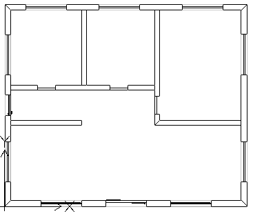
Plans
A plan drawing represents a horizontal slice through the BIM model. You can create floor plans.
You use a horizontal cutting plane to define a clipping box within the BIM model. Specify a depth to display entities of the BIM model below the cutting plane.
The BIM Navigator groups the plans in the Plans branch of the Drawings category in the BIM Navigator.
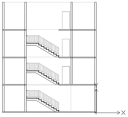
Sections
A section drawing represents a vertical slice through the BIM model.
The BIM Navigator groups the sections in the Sections branch.
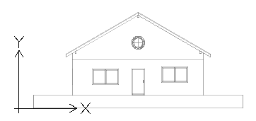
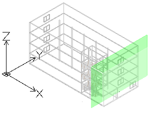
Elevations
Elevation drawings represent a vertical view of a building. Unlike Sections, Elevation drawings do not slice through the building. Rather they represent views of the BIM from the outside from different directions. You can create north, south, east, and west elevation drawings.
The BIM Navigator groups the elevations in the Elevations branch of the drawings list in the Drawings category.
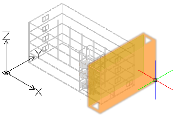
Working with the Clipping Box
The BIMSection command creates a clipping box with a specified width and depth. The first two points define the cutting plane position and the clipping box width, while the third point defines the drawing’s view direction and depth into the viewing direction. The software calculates the height from the extents of the BIM geometry.
At any time, you can resize the clipping box to include a specific part of the BIM model or change the position of the cutting plane using grip points on the drawing clipping box.
Note: Refresh the corresponding drawing after modifying the size of the clipping box or the cutting plane position.
If you delete the clipping box, the corresponding BIM drawing is also deleted. Also, if you delete a BIM drawing, the corresponding clipping box is also deleted.
You can control the clipping box display.
To display the clipping box:
- In the BIM Navigator, in Drawings, select a drawing.
- At the bottom of the palette, select Show Clipping Box.
Hovering over the cutting plane (the green plane in the BIM Model) displays the entire clipping box.
Controlling the Representation of BIM Entities in Drawings
When you create a drawing based on a BIM model, the software automatically generates a set of specific layers on which the entities are placed according to their location within the drawings clipping box relative to the cutting plane. Each layer name includes the drawing name as layer name prefix, which lets you identify the layers of a drawing.
Each BIM drawing has a flatshot cut and a flatshot forward layer:
- Flatshot cut. Contains a flatshot representation of BIM entities that cross the drawings cutting plane.
- Flatshot forward. Contains BIM entities that are beyond the cutting plane, in forward direction.
You can use the Layers Manager to specify different representation of BIM entities depending on BIM entity location within the drawings clipping box relative to the cutting plane. Additionally, for any BIM entity from the drawing, the Properties palette lets you change the hatch.
Example:
| Flatshot cut |  |
| Flatshot forward |  |
To create a plan from a BIM model:
- In the graphics area, set up a suitable 2D view. Use the Views command.
For example, display the plan view of a floor.
- Do one of the following:
- On the ribbon, click BIM > Drawings > Plan.
- Type BIMSection and specify the Plan option.
- In the command window, specify the name of the plan and press Enter.
The plan appears in the BIM Navigator, in the Plans branch.
Note: Clicking Isolated
to the right of the drawing in the drawing list in BIM Navigator displays the drawing in the graphics area. Clicking the button a second time hides the drawing and returns to the 3D model view.
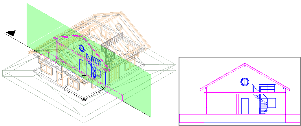
To create a section from a BIM model:
Before creating drawings, make sure you are working with the latest BIM model. Use the Reload from option to reload the latest BIM file from its location.
- In the graphics area, set up a suitable 3D view. Use the Views command.
- Do one of the following:
- On the ribbon, click BIM > Drawings > Section.
- Type BIMSection and specify the Section option.
A cutting plane is attached to the pointer.
Note: The cutting plane is perpendicular to the section line.
- In the graphics area, move the cutting plane preview to the desired location and click to specify the start point of the section line (P1).
- Specify the second point of the section line (P2).
- Specify a point or a value for the clipping box depth (P3).
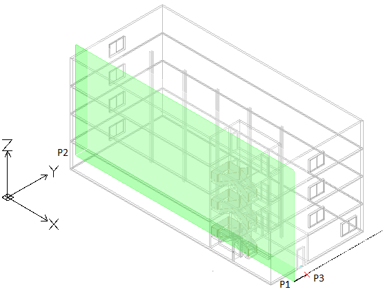
- In the command window, specify the name of the section and press Enter.
The section appears in the BIM Navigator, in the Section branch.
Note: Clicking Isolated
to the right of the drawing in the drawing list in BIM Navigator displays the drawing in the graphics area. Clicking the button a second time hides the drawing and returns to the 3D model view.
To create an elevation from a BIM model:
- In the graphics area, set up a suitable 3D view. Use the Views command.
- Do one of the following:
- On the ribbon, click BIM > Drawings > Elevation.
- Type BIMSection and specify the Elevation option.
A cutting plane is attached to the pointer.
- In the graphics area, move the cutting plane preview to the desired location and click to specify the start point of the elevation line (P1).
- Specify the second point of the elevation line (P2).
- Specify a point or a value for the clipping box width (P3).
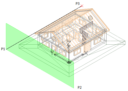
- In the command window, specify the name of the elevation and press Enter.
The elevation appears in the BIM Navigator, in the Elevation branch.
Managing BIM Drawings
The Drawings category of the BIM Navigator palette provides tools for working with drawings that you created from the BIM models imported into your project.
Note: The Drawings category appears only after you create at least one drawing.
Displaying Drawings
You can display each drawing in the graphics area, in the Model workspace.
To improve the drawing display, use hatches, various line colors and styles:
- Select drawing entities according to suitable criteria and specify the hatch in the Properties palette.
To display a drawing in the graphics area:
- On the BIM Navigator palette, click Drawings.
- In the drawing list, right-click the drawing to display and select Open from the context menu.
The drawing is displayed in a new drawing tab.
Alternatively, you can double-click the drawing to display. -
Note: All CAD entities from the drawing retain their BIM properties.
Refreshing Drawings
As the project evolves, various changes might be done within the BIM model. As the existing drawings may not reflect the changes, you must update them.
The update is required in the following situations:
- After reloading the BIM file to display its content in the form in which it was most recently saved.
- After modifying a drawing’s clipping box using grip points.
Before updating the drawings, reload the BIM file to display its content in the form in which it was most recently saved.
You can refresh each drawing individually or all drawings at once.
To refresh a BIM file:
- In the BIM Navigator palette, in BIM Files, right click a BIM file and select Reload from.
To refresh a drawing:
- In the BIM Navigator palette, in Drawings, do one of the following:
- Right-click a drawing and select Reload from from the context menu.
- Select a drawing and click Refresh
 .
.
The drawing is updated according to the BIM model latest state.
You can use the Refresh All button to refresh all drawings.
Deleting Drawings
If you delete the clipping box, the corresponding drawing is also deleted. Also, if you delete a drawing, the corresponding clipping box is also deleted.
To delete a drawing:
- In the BIM Navigator palette, select Drawings.
- In the drawings list, right-click the drawing to delete and select Delete from the context menu.
The drawing is deleted from the drawings list. The corresponding .dwg file is moved to a temporary folder from where you can recover it, if necessary. The corresponding clipping box is removed from the graphics area.
To delete a drawing from a sheet, delete its drawing title in the graphics area.
Placing Drawings on Sheets
You can place drawings on sheets. All sheets on which you place drawings created from the BIM model are listed in the drawings list, under the Sheets branch. All drawings that you placed on the sheet appear under the corresponding sheet.
When you place a drawing on a sheet, the software automatically places drawing callout symbol and drawing title under the drawing.
Drawing Callouts
Callout symbols call other drawings that are already placed on the same or other sheets.
Also calls out drawings that have been created but have not yet been placed on any sheet.
The software automatically fills the drawing sheet and drawing number fields in drawing callout symbols.
Drawing Titles
When you place a drawing on a sheet, the software automatically places drawing title under the drawing. The drawing title contains drawing name, scale, sheet number, and drawing number. The software fills in the drawing title’s sheet number from the name of the sheet tab. You can change the drawing number in the Properties palette. After modifying the drawing number value in the drawing title, the software replicates that number in all drawing callout symbols on all sheets that call that drawing’s title.
To place a drawing on a sheet:
Note: Refresh the drawings before placing the drawing on a sheet (BIM Navigator palette: Refresh All  ).
).
- Click on the Sheet tab on which you want to place the drawing.
- On the BIM Navigator palette, in Drawings, select a drawing.
- Do one of the following:
- Click Place on Sheet
 .
. - Right-click a drawing and select Place on sheet.
The drawing frame appears attached to the mouse cursor.
- Click Place on Sheet
- Specify the Scale option.
- Type the scale value and press Enter.
- In the graphics area, specify the drawing location.
In the BIM Navigator, in Drawings, the drawing is listed under the corresponding sheet. The drawing name includes the scale as well.
You can refresh the drawings at any time (BIM Navigator palette: Refresh All ).
To delete a drawing from the sheet:
Do one of the following:
- In the graphics area, select the drawing title and press Delete.
- On the BIM Navigator palette, in Drawings, expand the Sheets branch, right-click the drawing and select Delete from the context menu.
Annotating BIM Drawings
You can label BIM entities in a BIM drawing in order to provide detailed information.
Use labels to identify BIM entities in a BIM drawing.
This section discusses:
About Labels
Labels are annotations that you can use to identify BIM entities in a BIM drawing.
A label consists of a block that contains one or more attributes. Labels read and display BIM properties of the labeled BIM entity.
The software provides a Label Library that contains a set of predefined labels for each category of BIM entities. Additionally, you can define your own labels using user-defined Blocks and BlockAttributes.
You can assign a default label to the following categories of BIM entities:
- Doors
- Windows
- Walls
In addition to the default labels, you can define your own labels as Blocks containing BlockAttributes. BlockAttributes let you use Fields to refer properties of BIM entities in a user-defined label.
Once you create the label, the software creates a link with the BIM entity. When the corresponding BIM entities properties are modified, labels automatically update.
Labels remain associated with the BIM entities and update automatically when you modify the BIM model.
Labeling Tools
All tools for adding labels to BIM entities are grouped on the Annotate panel of the BIM ribbon tab.
- A generic tool lets you label any BIM entities.
- Specialized tools let you label certain BIM entities, such as doors, windows, and walls manually selected or all in one operation. During creation, doors and windows from the project are automatically assigned a unique number. Tipically, the specialized tools display the number of the BIM entity. You can use labels to display this number in your drawings.
| Icon | Meaning |
|
|---|---|---|
| Label Doors | Labels selected Door entities | |
| Label Windows | Labels selected Window entities | |
| Label Walls | Labels selected Walls | |
| Label All Doors | Labels all Door entities from the drawing | |
| Label All Windows | Labels all Windows entities from the drawing | |
| Labell All Walls | Labels all Walls entities from the drawing |
Labels provide detailed information
Access
Command: Properties
Labeling BIM Entities
Use the BIMLabel command to label BIM entities in a BIM drawing in order to provide detailed information.
The software provides a Label Library that contains a set of predefined labels for each category of BIM entities. Additionally, you can define custom labels that you can use to display additional properties of BIM entities.
Labels remain associated with the BIM entities and update automatically when you modify the BIM model.
The command lets you:
- Label one or multiple specified BIM entities
- Label BIM entities by category
Additional specialized tools let you label the following BIM entities individually or all at once:
- Doors
- Windows
- Walls
The specialized tools for creating labels are grouped in a flyout on the Annotate panel of the BIM ribbon tab.
To label specified BIM entities:
Note: Before starting, make sure that the block that you want to use as label exists.
- Isolate the BIM drawing in which you want to label the BIM entities.
- Do one of the following:
- On the ribbon, click BIM > Annotate > Insert Label.
- On the menu, click BIM > Label > Insert Label.
- Type BIMLabel.
- Type the name of a Block definition and press Enter.
Note: The command uses the specified Block to label all specified BIM entities, regardless of their type.
- In the graphics area, specify the BIM entities to label and press Enter.
All specified BIM entities are labeled.
To label BIM entities by category:
- Isolate the BIM drawing in which you want to label the BIM entities.
- Do one of the following:
- On the ribbon, click BIM > Annotate > Insert Label.
- On the menu, click BIM > Label > Insert Label.
- Type BIMLabel.
- Specify a block definition.
- Specify the Category option.
- Specify the category of BIM entities that you want to label:
- Type the name of a category and press Enter.
– or –
Specify the ? option to list the available categories in the command window.
- Type the name of a category and press Enter.
- In the graphics area, specify a set of BIM entities.
Only the BIM entities of the specified category are labeled.
Note: If you did not specified the category, the command will use the same label for all BIM entities from the selection.
Labeling Window Entities
Use Window labels to number Window entities within the .dwg file.
You can label all Window entities from the BIM drawing or a set of specified Window entities. The selection set can include various BIM entities. Only the Windows entities will be labeled.
To label specified Windows:
Note: Before starting, make sure that the block that you want to use as label exists.
- Isolate the BIM drawing in which you want to label the BIM entities.
- Optionally, specify a default label for Windows entities:
- In the BIM Label Library palette, right-click a label from the Windows category and select Set as Default for Windows.
- Do one of the following:
- On the ribbon, click BIM > Annotate > Label Windows.
- On the menu, click BIM > Label > Label Windows.
- Type BIMLabel.
- If you did not specify a default label, specify the block definition.
- In the graphics area, specify the Windows to label and press Enter.
Note: The selection set can include any BIM entity. Only the Windows entities will be labeled.
To add labels to all Windows in a BIM drawing:
Note: Before starting, make sure that the block that you want to use as label exists.
- Isolate the BIM drawing in which you want to label the BIM entities.
- Optionally, specify a default label for Windows entities:
- In the BIM Label Library palette, right-click a label from the Windows category and select Set as Default for Windows.
- Do one of the following:
- On the ribbon, click BIM > Annotate > Label All Windows.
- On the menu, click BIM > Label > Label All Windows.
- If you did not specify a default label, specify the block definition.
All Windows entities from the drawing are labeled.
Labeling Door Entities
Use door labels to number Door entities within the .dwg file.
You can label all Door entities from the BIM drawing or a set of specified Door entities. The selection set can include various BIM entities. Only the Doors entities will be labeled.
To label specified Doors:
Note: Before starting, make sure that the block that you want to use as label exists.
- Isolate the BIM drawing in which you want to label the BIM entities.
- Optionally, specify a default label for Doors entities:
- In the BIM Label Library palette, right-click a label from the Doors category and select Set as Default for Doors.
- Do one of the following:
- On the ribbon, click BIM > Annotate > Label Doors.
- On the menu, click BIM > Label > Label Doors.
- If you did not specify a default label, specify the block definition.
- In the graphics area, specify the Doors entities to label and press Enter.
Note: The selection set can include various BIM entities. Only the Doors entities will be labeled.
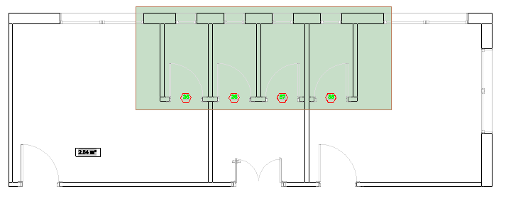
To add labels to all Doors in a BIM drawing:
Note: Before starting, make sure that the block that you want to use as label exists.
- Isolate the BIM drawing in which you want to label the BIM entities.
- Optionally, specify a default label for Doors entities:
- In the BIM Label Library palette, right-click a label from the Doors category and select Set as Default for Doors.
- Do one of the following:
- On the ribbon, click BIM > Annotate > Label All Doors.
- On the menu, click BIM > Label > Label All Doors.
- Type BIMLabel and specify the Doors category.
- If you did not specify a default label, specify the block definition.
All Doors entities from the drawing are labeled.
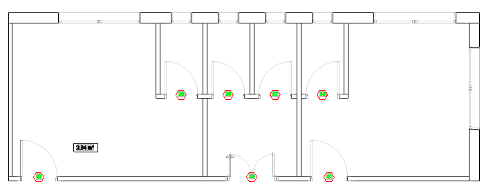
Access
Command: BIMLabel
Ribbon: BIM > Annotate > Insert Label
The Label Library Palette
The Label Library contains a set of predefined labels for each category of BIM entities.
The Label Library palette lists the labels available in the software, grouped according to their category. For each category of BIM entities, you can specify a default label.
- Clicking the plus sign (+) in front of a category displays the label list.
- Double-clicking the label name starts the BIMLabel command.
- Right-clicking a label name in the Label Library palette displays a context menu.
Use the BIMLabelLibrary command to display the Label Library palette.
To access the Label Library palette:
- Do one of the following:
- On the ribbon, click BIM > Annotate > Labels Library.
- On the menu, click BIM > Label > Labels Library.
- Type BIMLabelLibrary.
To hide the Labels Library:
- Type HideBIMLabelLibrary at the command prompt.
To specify a default label for a category of BIM entities:
- On the Label Library palette, expand the category for which to define a default label. For example, Windows.
- Right-click a label name and select the suitable option. For example, Set as Default for Windows.
Modifying Existing Dimensions for BIM Entities
There are the following methods for modifying dimensions for BIM entities:
- Using grip points
- Using the Properties palette
- Using the BIMDimensionEdit command
You can do various changes to existing dimensions:
- Add dimension points to a dimension
- Delete dimension points from a dimension
- Reverse the dimension direction
Use the BIMDimensionEdit command to modify existing dimension chains.
The command lets you:
- Add dimension points to dimension line
- Delete dimension points from dimension line
- Automatically dimension additional BIM entities within the same dimension chain
- Automatically update the dimension chain when a BIM entity is removed
The specialized tools for modifying dimensions are grouped on the Annotate panel of the BIM ribbon tab.
To add dimension points to a dimension line:
- Do one of the following:
- On the ribbon, click BIM > Annotate >
 .
. - On the menu, click BIM > Dimension > Dimension Edit > Add Point.
- Type BIMDimensionEdit and specify the Add points option.
- On the ribbon, click BIM > Annotate >
- In the graphics area, specify the dimension chain to modify.
- In the graphics area, specify the points to dimension and press Enter.
- Specify the dimension line using the chain index and press Enter. 0 means the first dimension line from the chain.
To delete a dimension point from a dimension chain:
- Do one of the following:
- On the ribbon, click BIM > Annotate >
 .
. - On the menu, click BIM > Dimension > Dimension Edit > Remove Point.
- Type BIMDimensionEdit and specify the Remove points option.
- On the ribbon, click BIM > Annotate >
- In the graphics area, specify the dimension chain from which to remove dimension points.
- On the BIM model, specify the point to remove.
Note: Make sure to specify only points corresponding to extension lines from the dimension chain.
To dimension additional BIM entities within a specified dimension chain:
- Do one of the following:
- On the ribbon, click BIM > Annotate > .
- On the menu, click BIM > Dimension > Dimension Edit > Add Entity.
- Type BIMDimensionEdit and specify the Add Entity option.
- On the ribbon, click BIM > Annotate >
- In the graphics area, specify the dimension chain to modify.
- Specify the BIM entities to dimension and press Enter.
Corresponding dimension points are added to the dimension chain.
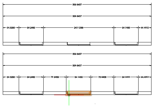
To detach a BIM entity from a specified dimension chain:
- Do one of the following:
- On the ribbon, click BIM > Annotate >
 .
. - On the menu, click BIM > Dimension > Dimension Edit > Remove Entity.
- Type BIMDimensionEdit and specify the Remove Entity option.
- On the ribbon, click BIM > Annotate >
- In the graphics area, specify the dimension chain from which to detach BIM entities.
- Specify the BIM entities to detach and press Enter.
The dimension points belonging to the specified BIM entities are removed from the dimension chain.
Access
Command: BIMDimensionEdit
Menu: BIM > Dimension > Dimension Edit
Mapping BIM Materials
In BIM files, such as .ifc and .rvt, material name is a property of entities of the BIM model. Materials in BIM software represent real materials, such as Steel, Concrete, Glass. They specify the graphical appearance in drawings. Additionally, where the application provides support for it, physical and thermal properties, and additional information, such as manufacturer and cost.
The BIM Material Mapper palette lists the material names that exist in the loaded BIM files and lets you map those BIM material names to the material available in the BIM Drawings Materials Styles Library.
The BIMMaterialMapper command displays the BIM Material Mapper palette.
When you load BIM files into the current DWG file, the available materials are loaded as well. For each BIM entity, the Material property in the Properties palette displays the material specified in the BIM file. After mapping the materials from the BIM file, the Material property of each BIM entity will display the corresponding material name that you mapped to in the Material Library.
When you create or refresh a drawing, and view it isolated on sheet, BIM entities are represented according to the style definition of the material in the Material Library.
After mapping the materials from the BIM file, BIM entities will be represented in drawings according to the style definition available for the corresponding material in the CAD software.
To display the BIM Material Mapper palette:
- Do one of the following:
- On the ribbon, click BIM > Palettes > Material Mapper.
- On the menu, click BIM > Materials > Material Mapper.
- Type BIMMaterialMapper.
To hide the BIM Material Mapper palette:
- Type HideBIMMaterialMapper at the command prompt.
The BIM Material Mapper Palette
The BIM Material Mapper palette displays the list of all materials from all BIM files that you loaded in the current DWG file. For each material from the list, you can select the corresponding material from the materials library available in the CAD software.
Displays options for filtering the materials from the list.
- IFC Materials. Displays only materials from the .ifc files loaded in the current DWG file.
- RVT Materials. Displays only materials from the .rvt files loaded in the current DWG file.
- All. Displays all materials from all BIM files loaded in the current DWG file.
- Mapped. Displays only mapped materials. For mapped materials, a preview displays in the list.
- Not Mapped. Displays only the materials that you have not mapped yet.
- Selected Entities Only. Displays only materials from the selected entities.
To map materials to materials from the CAD software:
- On the BIM Material Mapper palette, for each material from the list of material names that exist as properties of entities in the loaded BIM files, specify from the drop-down list in the Materials Library column the material you wish to map to.
Click and use the available options to filter the material list.
To display materials for specified BIM entities:
- In the graphics area, specify a set of BIM entities.
- On the BIM Material Mapper palette, click and select Selected Entities Only.
For example, if you select a set of walls for which the Material property is set to Concrete, only Concrete appears on the BIM Material Mapper palette.
Using the BIM Navigator
You can import BIM files, such as .ifc and .rvt files to your project and use various tools to modify them.
The BIM Navigator palette groups all tools necessary to import the BIM files and control the visibility of BIM entities in the graphics area.
You can:
- Import BIM files, such as .ifc and .rvt files.
- Control the access to a file. Unlocking the BIM file displays the file content in the graphics area.
- Control the visibility of the entities. You can show or hide entities and categories of entities from the BIM files that you imported in the current drawing.
To access the BIM Navigator palette:
- Do one of the following:
- On the ribbon, click BIM > Palettes > Navigator.
- On the menu, click BIM > Navigator.
- Type BIMNavigator.
The BIM Navigator Palette
The BIM Navigator palette groups the tools necessary to work with the BIM files content.
To display the BIM files in the current drawing and start using them, you must import the files. Once you import the files, the palette contains the following sections:
- BIM Files. Displays the list of BIM files that you imported in the current drawing and informations about the specified file. Unlocking a file displays the content in the graphics area and lists the entities in the Entities section.
- Filters. Displays the filtering tools.
- Entities. Displays contents from each imported BIM file in a tree view grouped according to their category and type. The tree view lets you browse the BIM file entities. Clicking an entity or a category of entities in the tree view selects the entities in the graphics area.
- Drawings. Displays the drawings created from the BIM model grouped according to their type.
BIM Files Category
Displays all files that you imported in the drawing.
File Properties List
Displays all BIM files that you imported in the drawing. These file types are listed:
- .ifc files
- .rvt files
Right-clicking a file displays the following options:
- Delete. Deletes the BIM file from the list.
- Unload. Unloads the BIM file
- Reload from. Resets the path to the BIM file.
Imported file properties include the following:
- Model Name: Displays the file name.
-
Visibility (Show or Hide): You can display only certain files in the graphics area. The button symbol indicates whether, in the graphics area, the drawing entities are shown or hidden. You can turn each file on or off independently.
-
Visible
-
Hidden
-
-
Locked or Unlocked: You can protect files so the entities from the model cannot be changed. The locked state prevents unintentional modification. If a file is protected, you cannot change, add, or delete entities from the model. Change the status to unlocked if you want to work with entities from the model.
-
 Locked
-
 Unlocked
-
General Information
Displays information about the BIM file selected in the list, such as file type and size.
Disciplines
Lets you control the display of the entities according to the discipline. Click All to select all disciplines or Clear All to cancel the selections.
The set of disciplines varies according to the model.
Filters Category
Filter drop-down list
Displays the list of all available filters. You can rename existing filters or delete unused ones.
Displays a menu with the following options:
- Rename. Renames the specified filter.
- Delete. Deletes the specified filter.

Displays the Data Extraction wizard.
Note: Save your drawing before starting the Data Extraction wizard.
BIM entities
Grups the tools for defining filtering criteria.
Criteria
Lets you specify the selection criteria.
The properties you can apply as selection criteria are: GUID, Name, Description, Predefined Type, Tag, Entity type.
-
Adds criteria to the criteria list.
-
Deletes criteria from the list.
Relational Operators
| Operator | Description | Examples |
|---|---|---|
| == | Equal | All Circles with radius=2.54 |
| != | Unequal | All Circles with radius other than 2.54 |
Group by
Defines the additional parameters to group by. Add as many parameters as necessary. When you add more than one parameters, BIM entities must meet all.
-
Adds the criterion to the criteria list.
-
Deletes the criterion from the criteria list.
The properties you can apply as grouping criteria are: Type, Floor, Space, Category.
Sort
Specifies the criteria according to which you want to sort the BIM entities. Additionally, you can specify an ascending or a descending order.
- Asc. Ascending order.
- Desc. Descending order.
The properties you can apply as sorting criteria are: Name, description, Predefined Type, Tag, and Entity Type.
Discard
Lets you end filter editing without saving the changes.
If the filter has changed since it was last saved, a prompt asks whether to save the changes. Click Yes to save the changes or No to discard them.
Save As
Saves the changes to a new filter.
Save
Saves the changes to the active filter.
Entity Category
Displays the entities of each imported BIM file in a tree view grouped according to their category and type.
Toolbar
Use the buttons in the toolbar at the top of the BIM Navigator palette for navigation and selection options:
- Filter drop-down list:
-
Hide/Show all entities : Shows or hides all entities from all imported BIM files.
-
Expand/Collapse all entities : Expands all categories from all imported BIM files.
Tree View
Displays the entities of each imported BIM file in a tree view grouped according to their category and type.
The sign () in front of a BIM file expands the categories list.
The sign ( ) in front of a BIM file collapses the categories list.
Visibility (Show or Hide): You can display only certain entities or certain categories in the graphics area. The button symbol indicates whether, in the graphics area, the BIM entities are shown or hidden. You can turn each BIM entity on or off independently.
-
Visible
-
Hidden
Drawings Category
Displays the drawings which you created based on the BIM model and sheets on which you have placed them.
Toolbar
| Button |
Function |
|---|---|
|
Place on Sheet
|
Places the specified drawing on the sheet |
|
Refresh All
|
Refreshes all drawings |
|
Refresh
|
Refreshes the drawing displayed in the graphics area |
Drawings and Sheets List
Displays all drawings that you created from the BIM model in a tree view, grouped according to their type. After placing the drawings on sheets, the corresponding sheets are added under the Sheet branch.
The following drawing types are listed in the tree view:
- Plans
- Sections
- Elevations
The tree view lets you browse the drawings and the sheets. Double-clicking a drawing in the tree view displays the drawing in the graphics area.
The sign () in front of a drawing category expands the drawing list.
The sign () in front of a drawing category collapses the drawing list.
Isolated: You can display one drawing at a time in the graphics area in the Model workspace. The Isolated button switches between displaying the selected drawing and displaying the BIM model. You can turn each drawing on or off independently.
-
Isolated
-
Unisolated
Right-clicking a drawing name displays the following options:
| Button |
Function |
|---|---|
| Place on Sheet | Places the currently selected drawing on the sheet |
| Refresh | Refreshes the current drawing |
| Isolate / Unisolate | Toggles between the drawing and the model |
| Delete | Deletes the specified drawing |
Selection Settings
Lets you control the display of the CallOuts symbols and clipping boxes.
Drawings Automation from RVT or IFC Models
You can automatically create annotated and dimensioned 2D DWG drawings, such as plans, sections, and elevations, from a BIM model.
The BIM drawings retain all the BIM information. Additionally, a link with the BIM model is created. When a new version of the BIM model is available, you can automatically update the BIM drawings.
Drawing creation consists of the following steps:
- Create 2D drawings from the BIM model (BIMAutoDrawings)
- Add dimensions (BIMAutoDimensions)
- Place all necessary labels by extracting information from BIM entities (BIMAutoLabels)
- Start Material Mapping (BIMAutoMaterialMapping)
- Place on Sheets (BIMAutoSheets)
You can run each step automatically using a dedicated command. Alternatively, you can run all steps at once using the BIMAutoAll command.
This topic discusses:
- Automatically Generatting All Drawings from a BIM Model
- Automatically Dimensioning BIM Drawings
- Automatically Annotating BIM Drawings
- Automatically Mapping BIM Model Materials
- Automatically Placing Drawings on Sheets
Automatically Generating Annotated Drawings from a BIM Model
Use the BIMAutoAll command to automatically create annotated and dimensioned 2D DWG drawings, such as plans, sections, and elevations, from the BIM model.
Each drawing created from the same BIM model is stored in a separate .dwg file. The command also creates sheets and inserts drawings on it at a specified scale.
BIM drawings retain all the BIM information. Additionally, a link with the BIM model is created. When a new version of the BIM model is available, you can automatically update the BIM drawings.
Each drawing type has a specific graphical display and appears in a different branch in the BIM Navigator.
The command launches successively all steps necessary for BIM drawing creation:
- Creates 2D drawings from the BIM model
- Adds dimensions
- Places all necessary labels by extracting information from BIM entities
- Maps existing BIM model materials to the application materials.
- Places drawings on separate Sheets
You can manually customize automatically generated drawings.
Automatically Generating All Drawings from a BIM Model
Use the BIMAutoDrawings command to automatically create all necessary 2D DWG drawings, such as plans, sections, and elevations, from the BIM model.
Each drawing created from the same BIM model is stored in a separate .dwg file.
BIM drawings retain all the BIM information. Additionally, a link with the BIM model is created. When a new version of the BIM model is available, you can automatically update the BIM drawings.
Each drawing type has a specific graphical display and appears in a different branch in the BIM Navigator.
Automatically Dimensioning BIM Drawings
Use the BIMAutoDimensions command to automatically place all necessary dimensions on all 2D DWG drawings, such as plans, sections, and elevations generated from the BIM model.
Each drawing created from the same BIM model is automatically dimensioned based on the information from the BIM model.
When a new version of the BIM model is available, you can automatically update the BIM drawings. You can refresh each drawing individually or all drawings at once. All existing dimensions will be automatically updated.
Automatically Annotating BIM Drawings
Use the BIMAutoLabels command to automatically place all necessary labels on all 2D DWG drawings, such as plans, sections, and elevations generated from the BIM model.
Entities from all drawings created from the same BIM model are automatically labeled based on the information from the BIM model.
When a new version of the BIM model is available, you can automatically update the BIM drawings. You can refresh each drawing individually or all drawings at once.
Automatically Mapping BIM Model Materials to the Application Materials
Use the BIMAutoMaterialMapping command to automatically map BIM material names that exist in the loaded BIM file to the material available in the BIM Drawings Materials Styles Library.
After mapping the materials from the BIM file, the Material property of each BIM entity will display the corresponding material name that you mapped to in the Material Library.
When you create or refresh a drawing, BIM entities are represented using the corresponding hatch pattern. The same representation is used when opening the BIM drawings and when placing on sheets.
Automatically Placing BIM Drawings on Sheets
Use the BIMAutoSheets command to automatically place each 2D drawing created from a BIM model on a separate Sheet.
The command automatically creates all sheets necessary for the drawings created from a BIM model.
Packaging Drawings
In practice, it may happen to forget to include dependent files such as References, referenced images, referenced PDF files, font files, font mapping files, PrintStyle files, and Print Configuration files.
You can create a ZIP file or a folder to bundle the drawing together with its related files.
Packages are used, for example, to distribute or send all necessary files together with their master drawing to clients or project partners, or to archive them.
This topic discusses:
- Creating Packages Containing a Drawing and Its Dependent Files
- Setting Preferences for Packaging Drawings
- Creating Packages from Drawing Sheet Sets
Packaging a Drawing and its Dependent Files
Use the PackAndGo command to create a package containing the current drawing and its dependent files such as References, referenced images, referenced PDF files, font files, font mapping files, PrintStyle files, and Print Configuration files.
You can create a ZIP file or a folder to bundle the drawing together with its related files.
Using the tabs of the Pack and Go dialog box, you can specify the files to add to the package. Optionally, you can display a summary of the package content.
To create a package containing a drawing and its dependent files:
- Click File > Export > Pack and Go (or type PackAndGo).
- In the Pack and Go dialog box, specify a view mode for the package file list:
- Tree View: Displays a hierarchical list of the package files, grouped by file type.
- Table View: Displays the included files a table format with file name, path, type, DWG file version, size, and date columns.
Select the check boxes in front of the file names to specify whether the file is included or excluded from the package. By default, all dependent files are included.
- Click Add File to add additional files to the package.
Use this option if you want to include other external files related to the drawing (but not directly referenced in it), such as customization files, text documents or spreadsheets.
- Click Settings to set preferences for the packaging.
- Set options in the Pack and Go Settings dialog box. See Setting Preferences for Packaging Drawings.
- Click View Report to view a summary of the package contents.
The Report dialog box shows detailed information about the package contents and provides distribution recommendations. The report may be written to a text file.
- For Package notes to include, you can type notes to include in the package (for example, project status information).
- Click OK.
- Type the file name for the ZIP file and click Save.
Access
Command: PackAndGo
Menu: File > Export > Pack and Go
Setting Preferences for Packaging Drawings
You can create a ZIP file or a folder to bundle the drawing together with its related files.
Using the options available in the Pack and Go Settings dialog box, you can:
- Create a ZIP archive file or gather the files in a specified folder.
- Specify how to organize the files and folders in the package.
- Discard all unused references from the drawing you pack.
To set preferences for packaging drawings:
- Do one of the following:
- On the menu, click File > Export > Pack and Go.
- In the Sheet Set Manager palette, on the Drawing Sheet List, right-click an item and select Pack and Go from the context menu.
- Type PackAndGo.
- In the Pack and Go dialog box, click Settings to set preferences for the packaging.
- In the Pack and Go Settings dialog box, under Packaging type and location, specify:
- Package type: Creates a ZIP archive file or gathers the files in the specified folder.
- File format: Specifies the existing drawing file format or saves to an earlier version.
- Target folder: Specifies the output folder for the package.
- File name option: Specifies what to do if a ZIP file with the same name already exists in the output folder (prompt for a file name, overwrite file, or increment file name).
- File name: Displays the ZIP file name (same as the master drawing name).
- Under Path options, specify how the files and folders are organized in the package (ZIP files or folders):
- Use organized folder structure: Creates a hierarchical folder structure based on the file structure. Click Browse to specify the root folder of the source.
- Place all files in one folder: Use this option if you are unsure whether the package recipient has a folder structure similar to yours.
- Keep files and folders as is: Recreates the exact paths of the existing files.
- Under Actions, specify actions performed before packaging the drawing:
- Bind References: Makes referenced drawings a permanent part of the master drawing. The option transforms referenced drawings to Blocks in the master drawing and incorporates dependent symbols such as Layers, LineStyle definitions, TextStyles, and DimensionStyles into the drawing. The option functions as if you use the -References command with the Bind option before packaging.
- Clean drawings: Discards all unused references from the drawing you pack. The option functions as if you use the Clean command before packaging.
- Under Include options, specify:
- Include fonts: Includes or excludes fonts used in the drawing in the package or from the package.
- Include unloaded References: Specifies whether links to reference files are maintained, although they are unloaded and no longer visible in the drawing. The Reference palette lets you unload and reload file references.
- Click OK.
- In the Pack and Go dialog box, click OK to start packaging.
Access
Pack and Go dialog box: Click Settings
Creating Packages from Drawing Sheet Sets
From the Sheet Set Manager palette, you can create a package from an entire drawing sheet set or subset, or from a single drawing sheet.
The Pack Go option is available in the Sheet Set Manager context menu.
The Pack and Go dialog box lets you specify the files that you want to include in the package.
To create a package from a drawing sheet set:
- In the Sheet Set Manager, open the drawing sheet set that you want to send.
- On the Drawing Sheet List tab, do one of the following:
- To pack an entire drawing sheet set: Right-click a drawing sheet set.
- To pack a drawing sheet subset: Right-click a drawing sheet subset
- To pack the specified drawing sheet or a drawing sheet selection: Right-click a drawing sheet
- From the context menu, select Pack and Go.
The Pack and Go dialog box appears.
- In the Pack and Go dialog box, specify the files to include in the package:
- On the Drawing Sheet tab, specify the drawing sheets to include in the package by selecting the checkbox in front of the drawing sheet name.
- On the Tree tab and the Table tab, add or remove drawing files, dependent files, and any other files.
- Click Settings to set preferences for the packaging.
- Set options in the Pack and Go Settings dialog box. See Setting Preferences for Packaging Drawings.
- Click View Report to view a summary of the package contents.
The Report dialog box shows detailed information about the package contents and provides distribution recommendations. The report may be written to a text file.
- Optionally, in Package notes to include, type notes to include in the package (for example, project status information).
- Click OK.
- Type the file name for the ZIP file and click Save.
Applying Digital Signatures for Authentication
You can associate digital signatures to drawing files for authentication.
To sign drawing files, you must have purchased a signature certificate from a service of a reliable Certificate Authority (CA):
- Reliable digital certificate providers meet requirements for safe digital signing.
- The CA issues a PFX file and a password to register in a certificate store.
- You need to install a root CA certificate as trusted.
- Class 3 of digital signatures is required.
A digital signature is a block of encrypted information attached to a file to electronically identify the originator.
A digital signature also securely indicates whether a file has been modified since the digital signature was applied.
Each drawing can have only one signature.
Note: A digital signature of a drawing file will become invalid if the file was modified after you signed it for authentication. Renaming a drawing file does not invalidate its digital signature.
You can sign drawing files, verify the authentication, and remove your signatures.
This section disusses:
- Signing Drawing Files for Authentication
- Verifying a Digital Signature in a Drawing
- Removing a Digital Signature from a Drawing
Signing Drawing Files for Authentication
Use the SignFile command to securely associate a digital signature to specified drawing files.
Digital signatures let you authenticate you as the signer.
You can sign drawing files (.dwg), drawing template files (.dwt), and drawing standard files (.dws).
A digital signature remains valid when a signed drawing is modified and saved in the same session. If a signed drawing is modified in another session, be it by the signer or another user, the signature is invalidated.
Note: To sign drawing files, you must have purchased a signature certificate from a service of a reliable Certificate Authority (CA).
To sign drawing files for authentication:
- Type SignFile at the command prompt.
- In the dialog box, under Files to be signed, specify the drawing files to sign.
The current drawing file appears in the list. You can add additional files, add complete folders, remove files from the list, and clear the list completely.
Note: Externally referenced drawings attached to listed files do not appear automatically in the list.
Use the following options to process multiple files in one signature operation:
- Include files from subfolders. Adds drawing files located in subfolders relative to the position of the current drawing file to the list.
- Add Files. Adds drawing files to the list.
- Add Folder. Adds all drawing files of the specified folder to the list.
- Remove. Removes the selected files from the list.
- Clear List. Removes all files from the list.
- From the list under Select a digital ID (Certificate), specify the digital ID to use to prove your identity.
You need at least one valid digital certificate file (.pxf) available on your system.
- Optionally, under Signature information add details:
- Select or clear Add time stamp.
- In Note, write individual information related to your authentication.
- Click Sign Files.
- Save the files you signed.
An icon at the right end of the Status Bar indicates whether a drawing file is signed. If the signature is valid, a stamp icon appears, and if it is invalid, the stamp icon appears stroked out. Click the icon to run the VerifySignature command.
Access
Command: SignFile
Verifying a Digital Signature in a Drawing
Use the VerifySignature command to validate a digital signature attached to the current drawing.
The command uses a main and a secondary dialog box:
- The Digital Signature Verification dialog box lets you examine whether the digital signature is valid and the drawing file has not been altered since it was signed.
- The Digital Signature Details dialog box lets you view details about the digital signature:
- File name and path
- Signature status. Shows whether the digital signature is valid and the drawing file has not been altered since it was signed.
- Digital ID details. Signer, Certificate issuer, validity period, signer’s note, signature date, and more.
To verify a digital signature in a drawing:
- Type VerifySignature at the command prompt.
- In the Digital Signature Verification dialog box, use these options:
- Display Base Signature. Displays information about the digital signature of the current drawing in the Digital Signature Details dialog box. This option is not available if the drawing is not signed.
- Display Reference Signatures. Displays information about digital signatures of externally referenced drawings (References) attached to the current drawing in the Digital Signature Details dialog box. This option is not available if the nested References are not signed.
- Ignore Reference Warnings. If this option is cleared, the Digital Signature Verification dialog box appears each time you attach an external drawing with a valid digital signature as Reference to the current drawing. The dialog box lets you examine status and information about the signature of the Reference drawing and probably signatures of nested Reference drawings.
- Click OK.
An icon at the right end of the Status Bar indicates whether a drawing file is signed. If the signature is valid, a stamp icon appears, and if it is invalid, the stamp icon appears stroked out. Click the icon to run the VerifySignature command.
Access
Command: VerifySignature
Removing a Digital Signature from a Drawing
Use the RemoveSignature command to remove an existing digital signature from the current drawing or from another drawing file.
Note: You cannot remove a digital signature from a file signed by another user.
To remove a signature from a drawing:
- Type RemoveSignature at the command prompt.
- Specify an option:
- Current drawing. Removes the digital signature from the current drawing.
- Specify file. From the dialog box, select the drawing file from which to remove the digital signature.
- Type Yes to confirm.
Access
Command: RemoveSignature
Using Drawing File Utilities
This section discusses:
- Setting Automatic Save and Backup Options
- Checking Integrity of Drawings
- Recovering Drawings
- Discarding Unused References
Setting Automatic Save and Backup Options
To protect your drawing files, use automatic save and backup options.
When a drawing closes normally, the autosave files are deleted.
To set automatic save and backup options:
-
Click Tools > Options (or type Options).
Click Application menu > Preferences (or type Options).
- In the Options dialog box, click System Options
 .
. - Expand Auto-save & Backup.
- Expand Automatic save file location to set the folder for automatically generated saved files (files of type .ds$).
Click Browse to browse for the folder.
- Expand Auto-save/backups to set:
- Enable auto-save: Automatically saves the drawing to autosave files (files of type .ds$). You can specify the interval for auto-save in minutes.
- Save backup at each save: Controls whether backup copies (files of type .bak) are created each time you save a drawing.
- Use original format: Specifies whether backup files are saved in its original drawing file version or in the current file version.
- Click OK.
Checking Integrity of Drawings
The Check command is a diagnostic tool for examining the current drawing and correcting errors. For any error detected, a description is provided in the command window.
Access
Command: Check
Menu: File > Error Check
Recovering Drawings
The Recover command partially recovers damaged drawing files. Use this utility when you experience difficulties opening an existing drawing. File damage may apply to only a part of the drawing; this utility helps to salvage undamaged drawing elements from the file.
To recover a damaged drawing:
- Click File > Recover (or type Recover).
- In the dialog box, select the file name of the damaged drawing, and click Open.
Access
Command: Recover
Menu: File > Recover
Recovering Drawings with the Drawing Recovery Manager
The Drawing Recovery Manager recovers drawings files if the system terminates unexpectedly, such as from a power failure, hardware issue, or software problem. The Drawing Recovery Manager palette opens the next time you start the application.
You can also use the DrawingRecovery command when you experience difficulties opening an existing drawing or if you want to check whether recoverable drawing files exist on your computer.
The Drawing Recovery Manager palette contains three sections:
| Palette Area | Description |
|---|---|
| Recovery Files tree view | Displays the files to recover as root entry. For each file the available autosave and backup files are listed. |
| Details list | Displays details about the drawing file: File name, folder, creation date and time, last saved date and time, file size, and the name of the user who last edited the file. |
| Preview area | Displays a preview of the drawing file. |
You can use these toolbar buttons at the top of the palette:
| Button | Description |
|---|---|
| Details View Toggle | Turns on and off the Details area of the palette. |
| Preview Toggle | Turns on and off the Preview area of the palette. |
The Drawing Recovery Manager supports these file types:
| File Type | Description |
|---|---|
| .dwg, .dws, .dwt | Drawing files, Drawing Standard files, Drawing Template files. These files are recoverable. |
| .ds$ | Autosave files. These are backup files created automatically from time to time. Use the Options command to specify the number of minutes between automatic saves the extension for autosave files: in the Options dialog box, click System Options > Autosave & Backup. |
| .bak | Backup files. These files are created in the same folder as the current drawing file every time that you manually save a drawing file. Use the Options command to turn on and off the creation of backup files: in the Options dialog box, click System Options > Autosave & Backup. |
| filename_recover_yyyy-mm-dd.dwg | Recovery files. These files result from an unexpected failure or crash where filename represents the original file name, and yyyy-mm-dd specifies the date when the problem occured. |
For more information about autosave and backup options, see Setting Automatic Save and Backup Options.
To recover drawings with the Drawing Recovery Manager:
- Do one of the following:
- Click File > Drawing Recovery Manager on the menu.
- Click Manage > Drawing Recovery Manager on the Application Menu.
- Type DrawingRecovery at the command prompt.
- On the palette, in Recovery Files, use these options:
| Execution | Description |
|---|---|
| Select a root file name entry, then right-click Open All (or double-click the root entry). | Opens all files which exist for the root entry. To recover one of the opened files, save it as .dwg file. |
| Select a file name below the root entry, then right-click Open (or double-click the file name). | Opens the specified file. To recover the file, save it as .dwg file. |
| Select a file name below the root entry, then right-click Properties. | Displays the drawing file Properties dialog box provided by the operating system. |
| Select a root file name entry, then right-click Remove. | Removes the file entry from the recovery list. Use this option if you do not need to recover the file. The autosave and backup file are maintained. The recovery file is deleted. |
To hide the Drawing Recovery Manager palette:
Do one of the following:
- Type HideDrawingRecovery at the command prompt.
- Click the Close Palette button.
If you close the Drawing Recovery Manager before resolving all affected drawings, use the DrawingRecovery command to reopen the palette.
Access
Command: DrawingRecovery
Menu: File > Drawing Recovery Manager
Application Button: Manage > Drawing Recovery Manager
Discarding Unused References
The Clean command removes unused references from the drawing. You can remove Block definitions, EntityGroups, Layers, defined drafting styles (such as LineStyles, TextStyles, DimensionStyles, and RichLineStyles), and other references as long as they are not referenced by other definitions or entities in the drawing file.
You can apply the command to all component types or to selected ones.
Discarding unused references can reduce a drawing’s file size. This command is useful before archiving or backing up drawings.
The Clean command does not remove defined views or coordinate systems because they are never referenced by another component of the drawing. To remove defined views, use the Views command. To remove defined coordinate systems use the CCS or CSStyle commands.
You cannot discard:
- Layer 0 (there must be at least one layer in the drawing)
- The LineStyles “Continuous”, “ByLayer”, and “ByBlock”
- The TextStyle “Standard”
- The TableStyle “Standard”
- The RichLineStyle “Standard”
- Layers that contain drawing entities
- LineStyles, TextStyles, TableStyles, and RichLineStyles referenced by drawing entities
- The active layer, LinesStyle, TextStyle, TableStyle, and RichLineStyle
To discard unused references:
- In the dialog box, select Show unreferenced entities.
- Set options:
- Delete dependent entities: Removes items and subordinate items that are not referenced by other entities.
- Confirm before delete: Displays the Confirm Clean dialog box for each item to remove.
- Click Delete to discard the selected items.
– or –
Click Delete All to discard all unused items.
Access
Command: Clean
Ribbon: Manage > Drawing > (Flyout) Clean
Comparing Drawings
The DrawingCompare command displays the Drawing Compare palette.
Use the DrawingCompare command to visually compare two drawings and identify changes that occurred from one version of the drawing to another.
The comparison result is displayed in the current drawing using different colors. Optionally, you can use clouds to mark entities that are different.
- Entities that are only in the current drawing (deleted entities)
- Entities that are only in the comparison drawing (new entities)
- Entities that are in both drawings
At any time, you can export the comparison result as a separate drawing.
As long as the comparison is active, the tool detects all modifications that occure in the current drawing.
Note: Entities that are on frozen layers are not taken into account.
Comparison Limitations
The drawing comparison has the following limitations:
- Works in Model mode only.
- Supports the following file types: DWG, DXF, DWT, DWS.
- Does not take into account the following entity types: OLE entities, cameras, geographic data, GIS entities, external references, such as DGN underlays, DWF underlays, PDF underlays, images, coordination models, and point clouds.
- Does not detect property changes, such as ByBlock and ByLayer within nested blocks.
- Does not make the difference between lines and polylines.
- Revision clouds do not include changes from a 3D isometric view.
- Does not allow you to compare the comparison result with a third drawing.
- Ignores Lineweight, lineStyle and colors.
- Explodes blocks.
To show the Drawing Compare palette:
- Do one of the following:
- Type DrawingCompare at the command prompt.
To hide the Drawing Compare palette:
- Type HideDrawingCompare at the command prompt.
To compare two drawings:
- Open the base drawing.
Note: Make sure you are working in Model mode.
- Type DrawingCompare at the command prompt.
- On the Drawing Compare palette, click Load file.
- In the Open File dialog box, browse to the file to compare with the current drawing.
- Click Open.
- On the Drawing Compare palette, click Toggle the comparison.
The graphics area displays the comparison result.
Example:
- Green circle – only in the current drawing
- Red circle – only in the comparison drawing
| Current drawing | Comparison drawing | Comparison result |
 |
 |
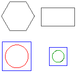 |
To export the comparison result:
- On the Drawing Compare palette, click Export comparison result.
- In the dialog box, specify the following:
- Save in: Navigate to the folder where you want to store the file.
- File name: Type a name for the file.
- Save as type: Select a file type for exporting.
- Click Save.
The Drawing Compare Palette
The Drawing Compare palette groups the tools for comparing two versions of a drawing.
From the Drawing Compare palette, you can:
- Load the drawing to compare with the current drawing.
- View the differences between two versions independently of LineStyle and LineColor.
- Browse and review changes between two versions of a drawing.
- Refresh
- Control the representation of differences in the graphics area
- Control the display of overlapping entities in the comparison result
- Display or hide hatches and text entities in the graphics area
Note: The Drawing Compare palette is available in the Model mode only. Using the DrawingCompare command in Sheet mode automatically switches the drawing to the Model mode.
The palette contains three sections:
- Differences: Lets you specify the color for the comparison result in the drawing.
- Clouds: Lets you specify the color, shape and size of the revision cloud.
- Filters: Lets you include or exclude hatch and text entities from the comparison result drawing.
In addition, there is a toolbar at the top of the palette.
Toolbar
Use the buttons in the toolbar at the top of the Drawing Compare palette for navigation and access options:
-
Toggles the comparison
 : Displays or hides the comparison result.
-
Back
 : Displays the previous difference.
-
Forward
 : Displays the next difference.
-
Export comparison result
 : Saves the comparison drawing in a specified location.
-
Refresh
 : Refreshes the Folder tree view, Contents list, and Preview area (for example, if changes were made externally to the selected folder).
Access
Command: DrawingCompare
Working with Drawing Standards
Drawing standards let you check drawings against custom and corporate standards.
Drawing standards are saved in drawing standards files of type *.dws.
You can check the following standards settings in a drawing to achieve conformity:
- Layers: Checks names, LineColor, LineStyle, and LineWeight properties. Layer display and locking settings (on/off, frozen/thawed, plotted/non-plotted, and locked/unlocked) are ignored.
- LineStyles: Checks names, segment length, and spacing definitions.
- DimensionStyles: Checks names and all Dimension variable settings. Dimension variable overrides are ignored.
- TextStyles: Checks names and all attributes of the TextStyle definition, including font name, font format, text height, obliquing angle, spacing, and orientation settings (upside down, backwards, and vertical).
This section discusses:
- Creating Drawing Standards Files
- Associating Drawing Standards and Setting Notification Options
- Verifying Drawing Standards
Creating Drawing Standards Files
Drawing standards are saved in drawing standards files of type *.dws. They are similar to regular drawing files, but designated to store the standards.
Use the VerifyStandards command to check the current drawing against drawing standards files.
To create drawing standards files:
- Create a drawing that has the standard names and properties for Layers, LineStyles, DimensionStyles, and TextStyles you want to apply for drawing standards checks.
- Click File > Save As (or type SaveAs).
- In the file dialog box, select Drawing Standards (*.dws) as file type.
- Specify a folder and file name.
- Click Save.
You can use an existing drawing for a standards file, but make sure to purge all Layers, LineStyles, DimensionStyles, and TextStyles that you do not want to include.
Associating Drawing Standards and Setting Notification Options
Use the DrawingStandards command to:
- Associate drawing standards to the current drawing
- Determine the drawing categories to check
- Set notification and audit options
To associate drawing standards to the current drawing:
- Click Tools > Standards > Drawing Standards (or type DrawingStandards).
- In the dialog box, expand Standards.
- Click New.
- In the file dialog box, specify the name for the drawing standard file (*.dws) to associate to the current drawing.
- Click Open.
- Optionally, repeat steps 2 and 3 to add more standards files to the list.
- Click Delete to remove a standard from the list.
- Standards from multiple standards files are checked in the order specified in the list. To change the priority, select an item, then click Move up or Move down.
- Under Settings, read information about the selected standard including drawing file name, drawing format (release version), last modification date, and who did the last change.
- Click Verify Standards to verify the associated standards immediately. This option runs the VerifyStandards command.
- Click Apply.
To determine the drawing categories to check:
- Click Tools > Standards > Drawing Standards (or type DrawingStandards).
- In the dialog box, expand Drawing Categories.
- Activate the drawing categories to include for verification with the VerifyStandards command:
- Note: Check at least one category to enable drawing standards checks.
- Click Apply.
To set notification and audit options:
- Click Tools > Standards > Drawing Standards (or type DrawingStandards).
- In the dialog box, expand Options.
- In Notification, select an option:
- Disable alert message: Turns off standards violation notifications.
- Pop-up alert over standards violation: Displays a pop-up alert when standards violations are detected in the current drawing (default).
- In Verify standards, specify options:
- Automatically fix nonstandard properties: Specifies whether to automatically fix nonstandard objects when you run the VerifyStandards command (cleared by default).
- Show ignored standards violations: Specifies whether to display standards violations that are flagged as ignored in the Verify Standards dialog box (selected by default).
- Preferred standards file: Sets a drawing standards file (*.dws) or None.
- Click Apply.
Access
Command: DrawingStandards
Menu: Tools > Standards > Drawing Standards
Ribbon: Manage > Standards > Drawing Standards
Verifying Drawing Standards
Use the VerifyStandards command to check that the current drawing conforms to industry, corporate, and custom standards.
The command checks whether names and properties of Layers, LineStyles, DimensionStyles, and TextStyles in the current drawing match those in associated standards files.
You can replace nonstandard items to be compliant, flag them to be ignored, or leave them as they are.
It is recommended to run the Clean command to purge unused objects before you run the VerifyStandards command.
To verify drawing standards:
- Click Tools > Standards > Verify Standards (or type VerifyStandards).
- In the dialog box, the category and name of an item that violates drawing standards are shown (for example DimensionStyle as category and the name of a DimensionStyle).
- In Replace with, select a drawing standard.
- The list may contain more than one standard because the drawing standards file may contain more than one object per category, or the list of drawing standards files defined for the current drawing contains more than one file.
- In Preview of changes, the differences between the current item verified for compliance and the standard selected in the replacement list are displayed. This list is empty if the item name differs, but not the properties.
- Optionally, set Ignore this standards violation to flag the current item as not to be replaced. The Ignored by information shows the login name of the user who set the ignore option. This status is stored with the drawing.
- Click Fix to accept the replacement of the current item by the specified drawing standard.
- Click Next to proceed to the next item.
- Repeat steps 2 through 5 for subsequent items to check for standards compliance.
- Click Close.
- At the end of the verification process, a summary screen reports the total number of standards violations, the number of automatically fixed items, the number of manually fixed items, and the number of items that have been marked as “ignored.”
In the Verify Standards dialog box, click Options to change the notification and auditing options during the verification process. This opens the Standards Configuration > Options section of the Options dialog box (as if you invoked the DrawingStandards command).
Access
Command: VerifyStandards
Menu: Tools > Standards > Verify Standards
Ribbon: Manage > Standards > Verify Standards