
Introduction
The following topics describe techniques and instruments for drawing with precision and accuracy:
- Coordinate Input and Coordinate Systems – How to enter coordinates and use coordinate filters
- Using Drawing Tools and Methods – How to use snap, grid, Ortho, EntitySnaps, ETrack, and polar guides
- Inquiring and Calculating – How to examine drawings by identifying coordinates, retrieving distances and areas, and analyzing geometries
Specifying Coordinates and Using Coordinate Systems
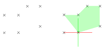
A coordinate system determines each point of a drawing surface or entity unambiguously. The drawing tool uses the Cartesian coordinate system consisting of three coordinate axes. Axes are arranged orthogonally, crossing at the origin. All axes use the same measurements.
The coordinates of a point are derived from the distance of the point to the X-, Y-, and Z-axis (optional), respectively.
- To enter points using the keyboard, use Cartesian coordinates, Cylindrical coordinates, or Spherical formats. Enter points as absolute or relative coordinates.
- To enter points by specifying X, Y, and Z coordinates independently, use coordinate filters.
World Coordinate System and Custom Coordinate Systems
The drawing tool differentiates between:
- The World Coordinate System (WCS) – A fixed coordinate system
WCS is a permanently installed Cartesian coordinate system used as a standard for all drawings. The X-axis measures the horizontal distance, the Y-axis measures the vertical distance from the origin. The Z-axis is orthogonal to the X- and Y-planes and measures the distance of a point to these planes. You cannot change the WCS.
-
Custom Coordinate Systems (CCS) – Arbitrary coordinate systems located anywhere and oriented in any direction in the WCS
A CCS is based on the WCS, but you can define it freely. You can:
- Move the origin to any point in the WCS
- Angle or turn the CCS around one or more axes in relation to the WCS
For example, you can make the drawing plane parallel to the entities to be drawn so that drawing 3D entities is easier.
To control CCSs, use the CCS and CSStyle commands.
Specifying Coordinates
All drawings are based on a Cartesian coordinate system in which three perpendicular axes are used: the X, Y, and Z. All axes originate in the origin point of the coordinate system. The X-axis and Y-axis define a horizontal plane. The X-axis and Z-axis, as well as the Y-axis and Z-axis, define vertical planes.
In the Cartesian coordinate format, a point is defined by its distances to the XY-, XZ- and YZ-planes. These distances are called the XYZ-coordinates of a point. When you draw in 2D, you specify points only on the XY-plane. The Z-coordinate is omitted. In CAD, the fixed Cartesion coordinate system is called the World Coordinate System (WCS). New drawings are based on the WCS.
Enter coordinates as absolute or relative values.
- To specify the point coordinates with respect to the previous point (relative coordinate input), type the “@” character in front of the coordinate values.
- To specify the point coordinates with respect to the previous segment (relative distance and relative angle input), type “@” character in front of the distance and angle values.
Absolute Coordinates
| Type of Coordinate | Input | Example |
|---|---|---|
| Cartesian (2D / 3D) | X,Y / X,Y,Z | 3.5,8.2,6.7 |
| Polar (2D) | distance<angle | 7.5<45 |
| Cylindrical (3D) | distance<angle,Z-coordinate | 7.5<45,12.2 |
| Spherical (3D) | distance<angle1<angle2 | 7.5<45<33 |
Relative Coordinates and Relative Angles
| Type of Coordinate | Input | Example |
|---|---|---|
| Cartesian (2D / 3D) | @deltaX,deltaY / @deltaX,deltaY,deltaZ | @3.5,8.2,6.7 |
| Polar (2D) | @relative_distance<angle @relative_distance TAB @relative_angle |
@7.5<45 @7.5 TAB @45 |
| Cylindrical (3D) | @relative_distance<angle,Z-coordinate @relative_distance TAB @relative_angle,Z-coordinate |
@7.5<45,12.2 @7.5 TAB @45,12.2 |
| Spherical (3D) | @relative_distance<angle1<angle2 @relative_distance TAB @relative_angle TAB @relative_angle |
@7.5<45<33 @7.5 TAB @45 TAB @33 |
To specify absolute Cartesian coordinates:
- Enter a command requiring coordinates, for example Line.
- Specify the X-, Y- and Z-coordinates separated by commas, for example 0,0,0.
- Specify subsequent coordinates to complete the command, for example 3.5,8.2,6.7.
- To place a point in the XY-plane (Z coordinate is zero), omit the Z-coordinate. For example, type 3.5,8.2.
To specify relative Cartesian coordinates:
- Enter a command requiring coordinates.
- Specify the first point, for example 0,0,0.
- To specify the second point with respect to the first point, type the “@” character in front of the coordinate values: @3.5,8.2,6.7.
To specify absolute polar coordinates:
- Enter a command requiring coordinates.
- Specify the first point, for example 0,0.
- Specify the second point using the 2D format, “distance<alpha_angle”, for example 7.5<45.
- distance: Specifies the distance from the origin
- alpha_angle: Specifies the angle in the XY-plane
To specify relative polar coordinates:
- Enter a command requiring coordinates.
- Specify the first point, for example 0,0.
- Specify the second point with respect to the first point using the 2D format, “@distance<alpha_angle”, for example @7.5<45.
To specify relative polar coordinates and relative angle:
- Enter a command requiring coordinates.
- Specify the first point, for example 0,0.
- Specify the second point with respect to the previous segment using the 2D format, “@relative_distance TAB @relative_angle”, for example @7.5 TAB @45.
To specify absolute cylindrical coordinates:
- Enter a command requiring coordinates.
- Specify the first point, for example 0,0,0.
- Specify the second point using the 3D format, “distance<alpha_angle,z_coordinate”, for example 7.5<45,12.2.
- distance: Specifies the distance from the origin
- alpha_angle: Specifies the angle in the XY-plane
- z_coordinate: Specifies the height above the XY-plane
To specify relative cylindrical coordinates:
- Enter a command requiring coordinates.
- Specify the first point, for example 0,0,0.
- Specify the second point with respect to the first point using the 3D format, “@distance<alpha_angle,z_coordinate”, for example @7.5<45,12.2.
To specify absolute spherical coordinates:
- Enter a command requiring coordinates.
- Specify the first point, for example 0,0,0.
- Specify the second point using the 3D format, “distance<alpha_angle<beta_angle”, for example 7.5<45<33.
- distance: Specifies the distance from the origin
- alpha_angle: Specifies the angle in the XY-plane
- beta_angle: Specifies the angle measured from the XY-plane (positive angles are measured above the XY-plane)
To specify relative spherical coordinates:
- Enter a command requiring coordinates.
- Specify the first point, for example 0,0,0.
- Specify the second point with respect to the first point using the 3D format, “@distance<alpha_angle<beta_angle”, for example @7.5<45<33.
Command Sequence
To specify absolute Cartesian coordinates:
: Line
Specify start point» 0,0,0
Specify next point» 3.5,8.2,6.7
…
To specify relative Cartesian coordinates:
: Line
Specify start point» 0,0,0
Specify next point» @3.5,8.2,6.7
…
To specify relative Polar coordinates and relative angle:
: Line
Specify start point» 0,0,0
Specify next point» 2,2,0
Specify next point» @3 TAB @45
…
Specifying Points Using Coordinate Filters
Use coordinate filters (XYZ Point Filters) to:
- Relate point inputs to the coordinates of existing entities
- Divide a point specification into separate X-, Y-, and Z-coordinates
You can enter combinations of these coordinate filters whenever a command prompts for a point: .x, .y, .z, .xy, .xz, .yz, and .xyz.
Coordinate filters are useful for 2D construction, especially when combined with EntitySnaps (ESnaps) methods. With ESnaps, you can obtain separate X, Y, and Z values from significant points on existing entities.
In 3D space, you can click the X- and Y-coordinates, then enter the Z-coordinate with the keyboard.
To specify points using coordinate filters:
- Type a command requiring coordinates, for example, Line.
- Specify the coordinate filter (.x, .y, .z, .xy, .xz, .yz, and .xyz).
- Specify the entity the filter applies to by entering the X or Y value of a point separately with respect to existing geometry.
- Specify additional points as needed.
Command sequences
To use coordinate filters in 2D drawings:
: Line
Specify start point» .x
of end
of <P1>
of <P2>
of (need YZ): end
of <P1>
Specify next point» @5<0
To identify the center of a cube:
: Point
Specify position» .x
of mid
of <P1>
of <P2>
of (need YZ): .y
of mid
of <P3>
of <P4>
of (need XZ): mid
of <P5>

Setting Up Custom Coordinate Systems
Use the CCS command to set coordinate systems and save, restore, rename, and delete them. By naming the current coordinate system, you can reuse it without reapplying the coordinate system parameters. The coordinate system is restored when you open the drawing again.
You can create multiple named coordinate systems for a drawing and use temporary unnamed coordinate systems.
Although you can have multiple custom coordinate systems in one drawing, only one can be the active coordinate system.
To set up a coordinate system:
- Click Tools > New CCS > 3 Point (or type CCS).
- Specify an origin point for the custom coordinate system.
- Specify a point through which the positive X-axis should run.
- Specify a point in the positive area of the XY-plane.
This point need not be located on the Y-axis.
- If needed, adjust the coordinate system to a drawn entity in space using EntitySnaps.
To set up a coordinate system by fixing the Z-axis:
Note: The Z-axis is not used in 2D design.
- Click Tools > New CCS > Z Axis Vector (or type CCS and specify the ZAxis option).
- Specify an origin point for the coordinate system.
- Specify a point through which the positive Z-axis should go, starting from the origin.
The option tilts the XP-plane orthogonally to the Z-axis.
To save a coordinate system:
- Type CCS and specify the Named option.
- Specify the Save option.
- Type a name for the CCS.
The CCS is saved to the name you specified.
To delete a coordinate system:
- Type CCS and specify the Named option.
- Specify the Delete option.
- If you are unsure of the name of the coordinate system to delete, specify the ? option to view a list of named coordinate systems.
Beneath the name, the origin of and direction vector of its three axes display in the command window.
- Specify a coordinate system to delete.
The named coordinate system is deleted.
To restore a saved coordinate system:
- Type CCS and specify the Named option.
- Specify the Restore option.
- If you are unsure of the name of the coordinate system to restore, specify the ? option to view a list of named coordinate systems.
Beneath the name, the origin of and direction vector of its three axes display in the command window.
- Specify a coordinate system to restore.
The named coordinate system is restored.
To align a coordinate system with an entity:
- Click Tools > New CCS > Entity (or type CCS and specify the Entity option).
- Select the entity with which to align the CCS.
- Type CCS and specify the Face option.
- Move the cursor over a face of a 3D solid or surface to preview the coordinate system.
- Click the face with which to align the coordinate system.
- Specify an option:
- Next face. Specifies the face adjacent to the selected one.
- X-axis flip. Rotates the CCS 180° about the X axis.
- Y-axis flip. Rotates the CCS 180° about the Y axis.
- Press Enter or specify the Accept face option to confirm the coordinate system and complete the command.
To switch to previous coordinate system views:
- Click Tools > New CCS > Previous (or type CCS and specify the Previous option).
You can step back through up to ten coordinate systems in the active ViewTile.
To align the coordinate system with the active viewing plane:
- Click Tools > New CCS > View (or type CCS and specify the View option).
The coordinate system aligns parallel to the active viewing plane.
To set the World Coordinate System (WCS) as the active coordinate system:
- Click Tools > New CCS > World (or type CCS and specify the World option).
The WCS becomes the active coordinate system.
To rotate the coordinate system about an axis:
- Click Tools > New CCS > X, Y, or Z (or type CCS and specify the X, Y, or Z option).
- Type the rotation angle about the chosen axis.
The coordinate system rotates about the specified axis. Rotating the coordinate system about the Z-axis is often used in 2D drawings, whereas rotating about the X- or Y-axis is used in 3D drawings.
 To rotate the coordinate system about two or three axes, repeat the step for each axis.
Access
Command: CCS
Menu: Tools > New CCS
Ribbon: View > Coordinates > CCS
Managing Custom Coordinate Systems
Use the CSStyle command to manage coordinate systems. You can:
- Manage coordinate systems by viewing, activating, renaming, or deleting them
- Select an orthographic coordinate system
- Adjust coordinate system settings
To create named Custom Coordinate Systems, use the CCS command.
To view saved coordinate systems:
- Click Tools > CCS Manager (or type CSStyle).
- In the Options dialog box, the Drawing Settings page opens and Coordinate System expands.
- Expand Named.
- Hover the pointer over a coordinate system to view the origin and X, Y, and Z coordinates.
To activate a coordinate system:
- Click Tools > CCS Manager (or type CSStyle).
- In the Options dialog box, the Drawing Settings page opens and Coordinate System expands.
- Expand Named.
- Select a coordinate system and click Activate.
- A
 displays beside the active coordinate system.
To delete or rename a coordinate system:
- Click Tools > CCS Manager (or type CSStyle).
- In the Options dialog box, the Drawing Settings page opens and Coordinate System expands.
- Expand Named.
- Select a coordinate system and click Delete or Rename.
- You can use Rename to name an unnamed coordinate system. You cannot delete or rename the World Coordinate System (WCS).
To set a temporary orthographic coordinate system on a face of a cube:
- Click Tools > CCS Manager (or type CSStyle).
- In the Options dialog box, the Drawing Settings page opens and Coordinate System expands.
- Expand Defaults.
- Select a face (Top, Bottom, Front, Back, Left, or Right) and click Activate.
- In Relative to, select the coordinate system to which the temporary coordinate system should be relative.
To set up coordinate systems:
- Click Tools > CCS Manager (or type CSStyle).
- In the Options dialog box, the Drawing Settings page opens and Coordinate System expands.
- Expand Options.
- Set options:
- Update view when coordinate system changes: Automatically displays the plan view to the coordinate system in the active ViewTile when the coordinate system changes.
-
Save coordinate system with view tiles: Forces all ViewTiles to reflect its active coordinate system. Otherwise, the coordinate systems of other ViewTiles remain unchanged.
To set up the coordinate system icon:
- Click Tools > Options (or type Options).
- Click Tools > Options (or type Options).
- Click Application menu > Preferences (or type Options).
- In the Options dialog box, click Drawing Settings
 .
. - Expand Display > Coordinate System Icon.
- Set options:
- Display icons: Displays the coordinate system icon.
- Display icons at origin: Displays the coordinate system icon at the origin (0,0,0) of the active coordinate system. If the origin is off the display, the coordinate system icon displays in the lower left of the view.
- Apply changes to all actively displayed views: Determines whether the coordinate system icon settings apply to all active views or only the active one.
Access
Command: CSStyle
Menu: Tools > CCS Manager
Ribbon: View > Coordinates > CCS Manager > CCS, Named CCS 
Specifying a Coordinate System for the Plan View
Use the PlanView command to set the plan view to the current coordinate system (the current construction plane), a previously saved Custom Coordinate System (CCS), or the World Coordinate System (WCS).
To specify a coordinate system for the plan view:
- Type PlanView at the command prompt.
- Type an option to specify a coordinate system:
- Active CCS: Sets the plan view to the active coordinate system.
- CCS: Sets the plan view to a previously saved Custom Coordinate System (CCS). Type the CCS name or specify the ? option to view a list of named coordinate systems.
- World: Sets the plan view to the World Coordinate System (WCS).
To force the view to set automatically to the plan view whenever the coordinate system changes:
- Click Tools > Options (or type Options).
- Click Tools > Options (or type Options).
- Click Application menu > Preferences (or type Options).
- In the dialog box, click Drawing Settings .
- Expand Coordinate System > Options.
- Select Update view when coordinate system changes.
- Click OK.
Access
Command: PlanView
Applying Dynamic Custom Coordinate Systems
The Dynamic Custom Coordinate System (Dynamic CCS) creates a temporary XY plane on a planar face of a 3D solid object so you can draw on that plane.
It works automatically and avoids creating a new CCS using the CCS command.
The Dynamic CCS applies when you run
- Commands which create 2D entities and 3D solids
- Text creation commands (Note and SimpleNote)
- The Block insertion command (InsertBlock)
- The drawing attachment command (AttachDrawing)
To turn Dynamic CCS on and off:
- Do one of the following:
- On the status bar, click the Dynamic CCS button.
- Press Ctrl + D.
- Press Ctrl + D.
- Press cmd + d.
- Press F6.
To apply Dynamic CCS:
- Start a command which supports the Dynamic CCS feature.
- Move the cursor over a planar face of a 3D solid object to set the temporary Dynamic CCS.
The edges of the planar face are highlighted.
The crosshairs, coordinate symbol, and grid change according to the Dynamic CCS XY plane.
- Complete the command.
Using the EnterPoint Tool
The EnterPoint command allows quick entry of drawing coordinates with precision whenever a point is requested.
The dialog box contains a numeric keypad for coordinate entry, an option to extend this point relative another point and a display showing the point’s equivalent Polar coordinate.
Coordinate
On the Coordinate tab, entering a point using the numeric keypad is simply achieved by selecting an X, Y or Z edit-box and typing in the required digits. Alternatively a particular coordinate can be selected with the X, Y and Z buttons.
When the relative point check box is set, the point entered in the X, Y and Z edit boxes is added to the Relative point and displayed as the Absolute point. The relative point can be set (via the Options tab) to always show the last point selected and may be re-selected by clicking the Relative point button.
The value displayed as the Absolute point is returned by the Enter point dialog when the OK button is selected. The Pick Point button cancels the dialog allowing normal selection of a point.
Direction
The Direction tab displays options for inputting a point using polar coordinate.
By entering digits into the Angle and Distance edit-boxes, the equivalent Cartesian coordinate is displayed at the Absolute point (when the relative point box is unchecked). The eight direction buttons make entering commonly used angles quicker.
Alternatively an angle or distance can be picked from the screen using the Angle and Distance buttons. Both the angle and distance values can be set with a single pick by setting Input Angle and Distance together from the Options tab (see below).
Options
The Options tab provides particular behavior for certain buttons and fields within the EnterPoint dialog box.
Options include:
- Remain on-screen: When unchecked, closes the dialog on the OK button. When checked, only the Cancel button closes the dialog.
- Input Angle and Distance together: When checked, inputs both the angle and distance when either an Angle or Distance button is selected.
- Preset Relative to Last point: When checked, automatically updates the Relative point field to the last point selected.
Access
Command: EnterPoint
Menu: Tools > EnterPoint
Using Drawing Tools and Methods
Use the following drawing tools and methods to create drawing entities:
- Specifying Drafting Options
- Setting Snap
- Displaying a Grid
- Setting Ortho Mode
- Switching Between Isometric Snap Grids
- Using EntitySnaps
- Understanding EntitySnap Modes
- Displaying EntitySnap Cues
- Using Polar Guides
- Changing the Display Order of Entities
Specifying Drafting Options
Use the DraftingOptions command to configure the drawing environment including EntitySnaps, snaps, grid display, EntityGrips, and entity selection.
To set up drafting tools and preferences:
- Type DraftingOptions at the command prompt.
In the Options dialog box, the User Preferences page opens and Drafting Options expands.
Pointer Control
To set up EntitySnaps:
- Type DraftingOptions at the command prompt.
In the Options dialog box, the User Preferences page opens and Drafting Options expands.
- Expand Pointer Control > EntitySnaps.
- Select Enable EntitySnaps (ESnaps) to enable or disable the use of entity snaps.
- Select Geometry ESnaps and Reference ESnaps so you do not need to invoke them as you draw. See Understanding EntitySnap Modes.
To set up snap options:
- Type DraftingOptions at the command prompt.
In the Options dialog box, the User Preferences page opens and Drafting Options expands.
- Expand Pointer Control > Snap Settings.
- Select Enable Snap to enable or disable snaps.
- Under Type, set:
- Standard (snaps to grid): Causes the pointer to snap to points at specified horizontal and vertical spacings.
- Radial (RSnap): Causes the pointer to snap to points along a radial vector. Polar guides must be on for this functionality to work.
- Under Spacing, set:
- Match Grid spacing: Forces the pointer to snap along vertical or horizontal grid points when specifying points.
- Horizontal Snap spacing: Sets the horizontal spacing of the snap grid.
- Vertical Snap spacing: Sets the vertical spacing of the snap grid.
- Match horizontal spacing: Transfers the value for horizontal spacing to the value for vertical spacing, so that grid display is evenly spaced in the X and Y directions.
- RSnap spacing: Specifies the spacing when using the RadialSnap type.
Note: You can customize snap and grid settings for each ViewTile.
Display
To set up EntityTrack guides:
- Type DraftingOptions at the command prompt.
In the Options dialog box, the User Preferences page opens and Drafting Options expands.
- Expand Display > ETrack and set:
- Enable EntityTracking (ETrack): Displays orthogonal (horizontal and vertical) tracking guides when the pointer moves over EntitySnap points. (EntitySnap guides must be enabled).
- Display ETrack guides across screen: Displays tracking guides. (EntitySnap guides must be enabled). When cleared, tracking paths display between the EntitySnap location and the pointer position.
- Enable Shift to acquire reference points: Displays tracking guides when you hold down Shift and move the pointer over an EntitySnap point.
To set up polar guides:
- Type DraftingOptions at the command prompt.
In the Options dialog box, the User Preferences page opens and Drafting Options expands.
- Expand Display > Polar guides.
- To enable polar guides, select Enable Polar guides (Polar). This option applies polar guide settings to EntitySnap pointers. The guides display along polar alignment angles from EntitySnap points (if ETrack is on).
- To display polar guides, select Display Polar guides. This option displays alignment paths.
- In Incremental angles for Polar guide display, select the angle increment to display and apply polar guides.
- Optionally, select or clear Display Polar guides at specific angle(s), and click:
- Add to specify individual values of angle increments for the use of polar guides.
- Delete to remove specified individual values from the list.
See also Using Polar Guides.
- To display a base angle guide, select Display zero angle base guide. This option displays a path line along the zero base angle according to the current Custom Coordinate System (CCS).
- In Polar Angle measurement, specify how to measure the elect settings for polar guides.
- Absolute. Measures the polar angle relative to CCS.
- Relative. Measures the polar angle relative to the last entity you create.
To set grid settings:
- Type DraftingOptions at the command prompt.
In the Options dialog box, the User Preferences page opens and Drafting Options expands.
- Expand Display > Grid Settings:
- Select Enable Grid to enable or disable the display of a pattern of evenly spaced dots that serve as a visual distance reference.
- Under Orientation, set:
- Rectangular: Orients the snap grid and grid display rectangularly.
- Isometric: Orients the snap grid and grid display at a 60° angle.
- Under Spacing, set:
- Match Snap spacing: Sets the grid spacing so that it matches the Snap settings.
- Horizontal display spacing: Sets the horizontal spacing of the grid.
- Vertical display spacing: Sets the vertical spacing of the grid.
- Match horizontal spacing: Transfers the value for horizontal spacing to the value for vertical spacing, so that grid display is evenly spaced in the X and Y directions.
To set drafting settings:
- Type DraftingOptions at the command prompt.
In the Options dialog box, the User Preferences page opens and Drafting Options expands.
- Expand Display > Pointer Cues and set:
- Display ESnap cues: Displays ESnap markers when the pointer encounters ESnap points. The highlighting shows the ESnap mode you can apply. You can also set the cue color.
- ESnap cue size: Sets the display size of ESnap markers.
- Expand Display > Gravity Box and set:
- Enable ESnap gravity: Pulls the pointer to an EntitySnap point when the pointer moves near the point.
-
Display GravityBox: Displays a box inside the crosshairs when you snap to an entity.
 When snap points come within this box, they become candidates for ESnaps. Adjust the GravityBox size.
Entity Selection
To set entity selection methods:
- Type DraftingOptions at the command prompt.
In the Options dialog box, the User Preferences page opens and Drafting Options expands.
- Expand Entity Selection > Selection Settings and set:
- Enable entity selection before commands. Lets you select entities first, then issue modifying commands on the selection set. If entities are not yet selected, you are prompted for entities. To clear the current selection set, press Esc. Pre-selection has no effect on Split, Trim, Extend, Chamfer, and Fillet commands.
- Enable hatch/boundary relations. Selects Hatch entities and boundary entities when you select a related Hatch.
- Enable EntityGroup selection sets. Selects all entities in an EntityGroup when you select one entity in that EntityGroup.
-
Number of entities to display properties. Limit the number of entities that can be changed at one time with the Properties palette. Specify a number between 0 and 32767. The default value is 25000. The value 0 turns the limitation off. Exceeding the limit grays out the property fields in the palette to indicate that they cannot be changed.
Note: When you specify the value 0 the limitation is turned off. Turning off the limitation can affect the performance of very large drawings.
-
EntityGroup display mode. Controls which EntityGrips are displayed for an EntityGroup selection.
- All entities. Displays all EntityGrips on all entities of the specified EntityGroup. You can modify each entity using its EntityGrips.
- Bounding box. Displays only one central EntityGrip for the entire EntityGroup, and a bounding box.
- EGroup. Displays only one central EntityGrip for the entire EntityGroup.
- SelectionBox size. Defines the display size of the SelectionBox (the pointer used to select entities).
To set entity selection highlighting:
- Type DraftingOptions at the command prompt.
In the Options dialog box, the User Preferences page opens and Drafting Options expands.
- Expand Entity Selection > Pre-selected highlighting and set:
- When prompted to specify entities or points. Previews selections when a command is active and prompts you to specify entities.
- Between commands. Previews selections when no commands are active.
To set preview filter:
- Type DraftingOptions at the command prompt.
In the Options dialog box, the User Preferences page opens and Drafting Options expands.
- Expand Entity Selection > Preview filter.
- In Exclude, select the entity type to exclude from selection previews:
- Entities on locked layers. Excludes entities on locked layers.
- Notes. Excludes Notes.
- References. Excludes entities in externally referenced drawings (References).
- Hatches. Excludes Hatches and Gradients.
- Tables. Excludes Tables.
- EntityGroups. Excludes entities in EntityGroups.
To set EntityGrips (EGrips) preferences:
- For EGrips Options, EGrips Color, and EGrips Size, see Setting EntityGrips Preferences.
To set ribbon options:
- Type DraftingOptions at the command prompt.
In the Options dialog box, the User Preferences page opens and Drafting Options expands.
- Expand Entity Selection > Ribbon Options and set:
- Display Contextual Ribbon. Displays the contextual ribbon tab when selecting an entity in the graphics area. For example, when you hatch an area, the Hatch Creation tab appears on the ribbon. All options from the Hatch dialog box are available on the contextual tab. The contextual tab is always the last tab on the ribbon and closes when you end the command.
- Retain pickfirst selections when commands are invoked from a contextual tab. Specifies whether the pickfirst selection set remains selected after starting a command from the contextual ribbon.
- Maximum entity selection for contextual tab display. Lets you specify the maximum number of entities that can be changed at one time with the property fields in the contextual ribbon tab. The initial value is 2500. Exceeding the limit of 32767 grays out the property fields in the contextual ribbon tab to indicate that they cannot be changed. The value 0 turns the limitation off. Turning off the limitation can affect the performance of very large drawings.
Dimension Palette
To set Dimension palette preferences:
- Type DraftingOptions at the command prompt.
In the Options dialog box, the User Preferences page opens and Drafting Options expands.
- Expand Dimension Palette.
- Click Enable Dimension palette to turn on or off the Dimension palette.
- In Favorites library path, set the path for Dimension text favorites files (*.dimfvt files). Click Browse to browse for the Dimension text favorites file folder.
Heads-up Display
To show or hide the Heads-up Display toolbar:
- Type DraftingOptions at the command prompt.
In the Options dialog box, the User Preferences page opens and Drafting Options expands.
- Expand Heads-Up Display.
- Select or clear Enable Heads-up toolbar. When selected, the toolbar displays when you select entities.
- In Heads-up toolbar display time, set a time (in milliseconds) before the Heads-up toolbar disappears from display.
OLE Editor
To set OLE Editor options:
- Type DraftingOptions at the command prompt.
In the Options dialog box, the User Preferences page opens and Drafting Options expands.
- Expand OLE Editor.
- Select or clear Use in-place editor to specify whether to edit Object Linking and Embedding (OLE) objects inside or outside the drawing.
Quick Input
To adjust Quick Input methods:
Access
Command: DraftingOptions
Setting Snap
The snap grid is an invisible grid in the graphics area. With snap activated, the pointer selects only points positioned directly on the snap grid. When you point to the drawing, start points, end points, center points, and other specific points lie exactly on points of the snap grid.
Use the Snap command to determine the distance between snap points. The snap grid follows the axes of the current coordinate system.
You can also use an isometric style of snap. Use isometric snap to create 2D isometric drawings representing 3D entities.
To turn snap on and off:
Do one of the following:
- Click Snap on the status bar.
- Press the F9 key.
- Press the F9 key.
- Press the Fn + F9 key.
To set snap:
- Type Snap at the command prompt.
- To specify snap spacing, type a positive number or select two points that reflect the snap spacing.
Typically, the snap grid coincides with the grid display defined by the Grid command. Another method is to set the snap grid to a partial fraction of the grid display.
- To turn snap on or off, specify the On or Off options.
- Set the X and Y spacing of the snap grid by specifying the Spacing option and specifying values for horizontal and vertical spacing.
- Specify the Grid style option and specify:
- Isometric. Sets up an isometric snap grid aligned along lines 30, 90, and 150 degrees from the horizontal axis. Specify vertical spacing for an isometric snap grid when prompted. Unlike rectangular snap, isometric snap cannot have different Spacing values. Use the IsometricGrid command to determine the active isometric plane to draw on (left, top, or right).
- Rectangular. Sets up an orthogonal snap grid aligned parallel to the X- and Y-axes of the current coordinate system.
- Specify the Orientation option to set the type of snap and specify:
- Grid. Toggles to standard snap.
- Radial. The radial snap grid aligns along polar angle increments. Specify the radial snap spacing.
Create a coordinate system using the CCS command to determine a different base point of the snap grid from the origin of the World Coordinate System (WCS). The CCS command lets you also rotate the snap grid.
Access
Command: Snap
Keyboard Shortcut: F9 to toggle snap mode
Keyboard Shortcut: F9 to toggle snap mode
Keyboard Shortcut: Fn + F9 to toggle snap mode
Status Bar: Snap (right-click for Settings)
Status Bar: Snap (right-click for Settings)
Status Bar: Snap
Displaying a Grid
Use the Grid command to display a latticed-point grid to visualize distances, angles, and entity relationships. The grid is not printed or plotted.
To set up the grid display:
- Type Grid at the command prompt.
- Type a spacing value or specify options:
- Drawing Bounds: Displays the grid beyond the area determined by the drawing bounds. Specify the Yes option to display the grid beyond the drawing bounds.
- Snap: Sets the grid interval to the current snap interval.
- Off: Turns the grid off.
- On: Turns the grid on using the current grid spacing.
- Spacing: Lets you set the horizontal and vertical spacing.
Access
Command: Grid
Keyboard Shortcut: F7
Keyboard Shortcut: F7
Keyboard Shortcut: Fn + F7
Status Bar: Grid (right-click for Settings)
Status Bar: Grid (right-click for Settings)
Status Bar: Grid
Setting Ortho Mode
Ortho mode limits the pointer movement so that the pointer moves parallel to the axes of the current coordinate system. You can only enter points located parallel to these axes. Ortho mode makes it easier to design and place parallel or collinear Lines on entities. In the standard World Coordinate System (WCS), orthogonal Lines run horizontally or vertically from the base point.
Ortho mode is effective only when pointing in the graphics area with the pointer. Ortho mode does not prevent you from entering non-orthogonal points using the keyboard.
To toggle orthogonal mode on and off:
- Type Ortho at the command prompt (or click Ortho on the status bar).
- Specify an option:
- Yes: Turns Ortho mode on.
- No: Turns Ortho mode off.
- – or –
- Click Ortho on the status bar.
- – or –
- Press the F8 key.
- Press the F8 key.
- Press the Fn + F8 key.
Access
Command: Ortho
Keyboard Shortcut: F8
Keyboard Shortcut: F8
Keyboard Shortcut: Fn + F8
Status Bar: Ortho (right-click for Settings)
Status Bar: Ortho (right-click for Settings)
Status Bar: Ortho
Switching Between Isometric Snap Grids
When you create isometric drawings, you can switch between three isometric snap grids: left, top, and right.
To switch between isometric snap grids:
- Make sure that snap mode is on and the snap style is set to Isometric.
- Type IsometricGrid at the command prompt or press F5.
- Type IsometricGrid at the command prompt or press F5.
- Type IsometricGrid at the command prompt or press Fn + F5.
- Specify an option:
- Left: Aligns the snap grid along the left plane, defined by the 90° and 150° axis pair.
- Right: Aligns the snap grid along the right plane, defined by the 90° and 30° axis pair.
- Top: Aligns the snap grid along the top plane, defined by the 30° and 150° axis pair.
- Orthogonal mode alignes along the isometric axes determined by the chosen plane. The three isometric axes are 30°, 90°, and 150°.
Access
Command: IsometricGrid
Keyboard Shortcut: F5
Keyboard Shortcut: F5
Keyboard Shortcut: Fn + F5
Using EntitySnaps
Use EntitySnaps (ESnaps) to detect and snap to points on drawing entities, for example, end points, intersections, and center points. Snapping to a point provides an exact position for drawing and editing commands.
You specify ESnap modes to set snap options. For example, you might want to snap to intersections between entities. You can apply ESnap modes permanently or for a single operation.
ESnap modes are not universally applicable. For instance, you cannot define the end point of a circle. Similarly, a line segment has no central point. However, a drawing entity might contain several points that match the ESnap mode criteria. A line entity or an arc, for instance, always has two end points. In those cases, the ESnap function identifies the nearest possible points. Always place the pointer as near as possible to the desired point.
The pointer snaps to a point depending on the:
- Type of drawing entity
- Selected EntitySnap mode
- Specific point on the selected entity
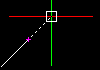
The illustration below shows the relation between the point selected ( ) and the point snapped (
 ):
):
To use EntitySnaps when prompted for point selection:
- Invoke a command or function that requires a point selection.
- Do one of the following:
- Right-click and click ESnap Overrides, then select an ESnap.
- Type an EntitySnap mode abbreviation.
- Move the pointer toward an entity where you want to use the ESnap.
The ESnap cue appears on the entity according to the ESnap mode you selected.
To apply the EntitySnap function ‘end’, for example:
: LINE
Specify start point» <click in graphics area>
Specify next point» end
of: <point to drawing entity>
Specify next point»
To set EntitySnaps permanently:
- Do one of the following:
- Right-click the ESnap button on the status bar and click Settings.
- Type EntitySnap at the command prompt.
- Click Tools > Options (or type Options), click User Preferences
 , then expand Drafting Options > Pointer Control > Entity Snaps.
 - Click Tools > Options (or type Options), click User Preferences , then expand Drafting Options > Pointer Control > Entity Snaps.
- Click Application menu > Preferences (or type Options), click User Preferences , then expand Drafting Options > Pointer Control > Entity Snaps.
- In the dialog box, select Enable EntitySnaps (ESnaps).
- Under Geometry ESnaps and Reference ESnaps, select the EntitySnap modes you want to apply.
The selected modes are permanently activated.
You can suspend EntitySnaps by typing non when prompted to select a point.
Understanding EntitySnap Modes
| EntitySnap Mode | Abbreviation | Marker | Description | Example |
|---|---|---|---|---|
| Center | cen |  |
Snaps to the center of a Circle, Ellipse, Ring, or Arc. | 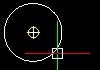 |
| Endpoint | end |  |
Snaps to the end point of a Line, Arc or other entity. Planes or edges of solids are also interpreted as lines, and end points of planes and solids can be recognized by Endpoint mode. The mode does not differentiate between the start or end point of an entity. | 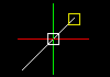 |
| Extension | ext | – | Snaps to the extension of an entity or to the intersection of the extension of two entities. A temporary extension line or arc displays as a dotted line when you pass the pointer over the end point of entities and lets you specify a point for the extension. To snap to the extension of two entities, first move the pointer over the end point of an entity. The entity is marked for extension. Then move the pointer over the end point of another entity. This entity is marked too. Finally, move the pointer near the intersection of the extensions. An X indicates the intersection. Click to accept the snap. |
 |
| Geometric center | gce | Snaps to the centroid of a closed Polyline, planar 3D Polyline, Spline, Region, or planar face of a 3D Solid object. | 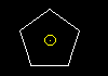 |
|
| Geometric center | gce | Snaps to the centroid of a closed Polyline, planar 3D Polyline, Spline, Region, or planar face of a 3D Solid object. | |
|
| Insertion point | ins |  |
Snaps to the insertion point of a Block insertion, an attribute, or a Text entity. | 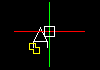 |
| Intersection | int |  |
Snaps to the intersection points of Lines, Arcs, and Circles, or any combination of them. | 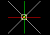 |
| Midpoint | mid |  |
Snaps to the mid point of a Line or an Arc. Planes, or the edges of solids, are also interpreted as lines and can be snapped to with the Midpoint mode. | 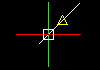 |
| Node | nod |  |
Snaps to a point entity, dimension definition point, or Dimension text origin. | 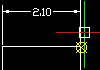 |
| Nearest | nea |  |
Snaps to the next situated point of an entity when at least one point of the entity lies within the borders of the GravityBox. If you select a point without using Nearest mode, the selected point might not be on the desired entity. This mode ensures that the entities share a point with the specified entity. | 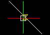 |
| Parallel | par |  |
Constrains a linear entity to be parallel to another linear entity. When prompted to specify a second or next point when drawing a vector, move the pointer over an existing linear entity until you see the Parallel EntitySnap marker. Move the pointer close to a parallel position. A dotted line appears, indicating the parallel ESnap. Click the second point of the line on the parallel. | 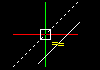 |
| Perpendicular | per |  |
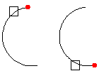
Requires that a start point for a function has been selected. Activating the EntitySnap mode relates this point to the snapped point. For instance, select the end point for the perpendicular, and Perpendicular mode is activated. The result is a perpendicular Line from the end point to the selected entity. | 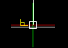 |
| Quadrant | qua |  |
Snaps to the nearest quadrant of a Circle or Arc. Quadrants refer to the points of a Circle or Arc on the circumference at 0°, 90°, 180° and 270°. These are the intersecting points of the axes of a coordinate system upon whose origin lies at the center of the Circle or Arc with the circumference of the Circle or Arc. Only the next visible quadrant of an Arc can be snapped. | 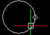 |
| Tangent | tan |  |
Requires that a start point for a function has been selected. Activating the EntitySnap mode relates this point to the snapped point. For instance, to create a Line tangent to a Circle, select the end point for the tangent Line, and Tangent mode is activated. The result is a tangent Line from the end point to the chosen entity. | 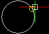 |
| Visual intersection | appint |  |
Snaps to the location in the plan view of the current coordinate system where two entities would intersect if they were projected onto the plan view. In 3D space, Visual intersection mode snaps to two entities that might or might not actually intersect, whereas, in 2D drafting, it snaps to the projected intersection of two Line entities. If the GravityBox covers only one drawing entity when snapping, you are prompted to select a second entity. | 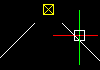 |
Other Precision Input Methods
| Precision Input Method | Abbreviation | Description |
|---|---|---|
| From reference point | from | Locates a point offset from a specified reference point. |
| Midpoint between two points | m2p, or mtp | Snaps to the midpoint between two specified points. |
Setting EntitySnaps
Use EntitySnaps (ESnaps) to detect and snap to geometrically significant points on drawing entities, for example, end points, intersections, and center points. Snapping to a significant point provides an exact position for drawing and editing commands.
To set EntitySnaps:
- Click Tools > Options (or type Options), click User Preferences , then expand Drafting Options > Pointer Control > Entity Snaps (or type EntitySnap).
- Click Tools > Options (or type Options), click User Preferences , then expand Drafting Options > Pointer Control > Entity Snaps (or type EntitySnap).
- Click Application menu > Preferences (or type Options), click User Preferences , then expand Drafting Options > Pointer Control > Entity Snaps (or type EntitySnap).
- Select Enable EntitySnaps (ESnaps).
- Under Geometry ESnaps and Reference ESnaps, select EntitySnap modes so that you do not need to invoke them as you draw.
- Click OK.
Access
Command: EntitySnap
Status Bar: ESnap (right-click for Settings)
Status Bar: ESnap (right-click for Settings)
Status Bar: ESnap
Displaying EntitySnap Cues
EntitySnap (ESnap) cues help you detect significant geometric points on drawing entities by displaying symbols and tooltips as you move the pointer over ESnap points. ESnap cues work directly with currently active ESnaps – you can configure which entity snap modes are applied.
As the pointer moves a line segment end point within the pointer snap box, a square displays, identifying the active ESnap and its location. Also, an Endpoint tool tip displays, naming the applicable ESnap.
ESnap cues display only while commands that require point selection are active. Only one ESnap is in control for any given pointer position, with the exception of the Center ESnap, where a section of the Circle itself must be within the pointer snap box. If more than one ESnap point is within range, the closest point takes precedence. As the pointer moves closer to another ESnap point, the ESnap cue changes to correspond with the second snap point.
To turn on and off ESnap cues:
- Click Tools > Options (or type Options).
- Click Tools > Options (or type Options).
- Click Application menu > Preferences (or type Options).
- Click User Preferences .
- Expand Drafting Options > Display > Pointer Cues.
- Select or clear Display ESnap cues.
- Click OK.
To set the color of ESnap cues:
- Click Tools > Options (or type Options).
- Click Tools > Options (or type Options).
- Click Application menu > Preferences (or type Options).
- Click User Preferences .
- Expand Drafting Options > Display > Pointer Cues.
- In the LineColor list, select a color.
- Click OK.
To set the size of ESnap cues:
- Click Tools > Options (or type Options).
- Click Tools > Options (or type Options).
- Click Application menu > Preferences (or type Options).
- Click User Preferences .
- Expand Drafting Options > Display > Pointer Cues.
- Move the Esnap cue size slider to set the pointer snap box size.
- Click OK.
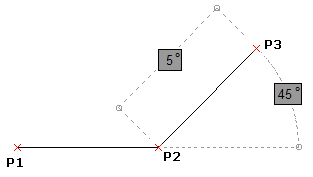
Using Polar Guides
Use polar guides to draw at exact angles and fixed intervals, starting from 3 o’clock (or East) and at additional angle increments.
A path line displays if the SelectionBox crosses a geometric point and the pointer moves close to one of the polar guide angles.
To turn on and off polar guides:
- Click Polar on the status bar.
- – or –
- Press the F10 key.
- Press the F10 key.
- Press the Fn + F10 key.
To adjust polar guides settings:
- Right-click Polar on the status bar and click Settings.
- – or –
- Click Tools > Options (or type Options), click User Preferences , then expand Drafting Options > Display > Polar Guides.
- Click Tools > Options (or type Options), click User Preferences , then expand Drafting Options > Display > Polar Guides.
- Click Application menu > Preferences (or type Options), click User Preferences , then expand Drafting Options > Display > Polar Guides.
- To enable polar guides, select Enable Polar guides (Polar). This option applies polar guide settings to EntitySnap pointers. The guides display along polar alignment angles from EntitySnap points (if ETrack is on).
- To display polar guides, select Display Polar guides. This option displays alignment paths.
- In Incremental angles for Polar guide display, select the angle increment to display and apply polar guides.
- Optionally, select or clear Display Polar guides at specific angle(s), and click:
- Add to specify individual values of angle increments for the use of polar guides.
- Delete to remove specified individual values from the list.
- Click OK.
Access
Keyboard Shortcut: F10
Keyboard Shortcut: F10
Keyboard Shortcut: Fn + F10
Status Bar: Polar (right-click for Settings)
Status Bar: Polar (right-click for Settings)
Status Bar: Polar
Tracking and Setting Inference Points
While running a command you can set temporary points to which you can refer to later in command execution. This is useful in the construction process by setting inference points which relate to the geometry of other drawing entities.
Although you can set freely temporary points during a command execution (see first command sequence below), setting these reference points is applied practically in conjunction with Polar Tracking and EntitySnaps being active (see second command sequence).
To set temporary reference points:
- Run a command which requires point entry, such as the Line or PolyLine command.
- When being prompted to specify a point,
- – or –
- Right-click and select ESnap Overrides > Inference point from the context menu.
- Specify a temporary point.
- If necessary, repeat step 2 and 3 to set more temporary points.
- While continuing drafting, snap to temporary points using the ESnap option Node.
When you execute another command, temporary points set in the previous command are deleted automatically.
To set temporary inference points applying tracking and entity snaps:
- Make sure ESnap is on.
- Clicking ESnap in the status bar or pressing the F2 key toggles running EntitySnaps on and off.
- Clicking ESnap in the status bar or pressing the F2 key toggles running EntitySnaps on and off.
- Clicking ESnap in the status bar or pressing the Fn + F2 key toggles running EntitySnaps on and off.
- Make sure some running EntitySnap modes are set, among them the Node mode.
Right-click ESnap in the status bar, select Settings from the pop-up menu, and set EntitySnap modes in the Options – User Preferences dialog box.
- Make sure Polar Tracking and/or Entity Tracking is on.
- Clicking Polar in the status bar or pressing the F10 key toggles polar tracking on and off.
- Clicking Polar in the status bar or pressing the F10 key toggles polar tracking on and off.
- Clicking Polar in the status bar or pressing the Fn + F10 key toggles polar tracking on and off.
- Clicking ETrack in the status bar or pressing the F11 key toggles entity tracking on and off.
- Clicking ETrack in the status bar or pressing the F11 key toggles entity tracking on and off.
- Clicking ETrack in the status bar or pressing the Fn + F11 key toggles entity tracking on and off.
- Run a command which requires point entry, such as the Line or PolyLine command.
- When being prompted to specify a point,
- – or –
- Right-click and select ESnap Overrides > Inference point from the context menu.
- Move the cursor over a significant point of an entity to which a running ESnap could be applied.
Move the cursor to the left or right (or up or down) until the tracking guide appears.
Move the cursor over another significant point of an entity to which a running ESnap could be applied.
Move the cursor up or down (or to the left or right) until the tracking guide appears.
Move the cursor near the virtual intersection of the previously detected tracking guides until the crossing tracking guides appear.
- Click to set the temporary reference point at that intersection.
- If necessary, repeat step 5 and 7 to set more temporary points.
- While continuing drafting, snap to the temporary reference points you have set using the EntitySnap option Node.
Activate the ESnap option Node permanently when you want to apply inference points within a command.
Access
Context Menu: ESnap Overrides > Inference point
Inquiring and Calculating
Use the following functions for quick inquiries including coordinate information, distances between two points, total area of entities, and entity details:
- Identifying Coordinates
- Measuring Distances
- Measuring Angles
- Calculating Areas
- Measuring Geometries
- Listing Entity Information
- Using the SmartCalculator
- Using the SmartCalculator
- Using the SmartCalculator
- Invoking the OS Calculator
Identifying Coordinates
Use the GetXY command to determine the coordinates of a point.
GetXY can be used as a transparent command.
To identify the coordinates of a point:
- Click Tools > Inquiry > Get Coordinate (or type GetXY).
- In the graphics area, select the point to identify.
The coordinates display in the command window.
If the point you want to determine is geometrically significant, for example, a start or end point of a drawing entity, use EntitySnaps.
Access
Command: GetXY
Menu: Tools > Inquiry > Get Coordinate
Ribbon: Home > Tools > Inquiry > Get Coordinate
Ribbon: Manage > Utilities > Inquiry > Get Coordinate
Measuring Distances
Use the GetDistance command to measure distances or angles between two points. You can use the command as a transparent command. The points can be arbitrary and not part of a drawing.
You can also use the Distance option of the MeasureGeometry command.
To measure distances between points:
- Click Tools > Inquiry > Get Distance (or type GetDistance).
- In the graphics area, select two points between which to measure.
If the distance you want to determine has geometrically significant points, for example, start or end points of a drawing entity, use EntitySnaps.
The resulting measurements display:
Distance = <n>, Angle in XY Plane = <n>, Angle from XY Plane = <n>
Delta X = <n>, Delta Y = <n>, Delta Z = <n>Distance: Measures the absolute distance between points.
Angle in XY Plane: Measures the angle to the second point starting from the X-axis. The measurement displays the lesser-valued angle no matter what the rotation direction.
Angle from XY Plane: Measures the angle between the first and second point from the XY-plane to the Z-axis. The first point is assumed to lie on the XY-plane.
Delta X, Delta Y, and Delta Z: Measures the distance between the two points in the direction of the respective axis of the coordinate system. Length values are specified in drawing units.
Press F2 to better view the result in a separate window.
Access
Command: GetDistance
Menu: Tools > Inquiry > Get Distance
Ribbon: Home > Tools > Inquiry > Get Distance
Ribbon: Manage > Utilities > Inquiry > Get Distance
Measuring Angles
Use the GetAngle command to measure angles associated to arcs and angles between lines or arc endpoints.
You can use the command as a transparent command. The lines can be arbitrary and not part of a drawing.
You can also use the Angle option of the MeasureGeometry command.
To measure angles:
- Type GetAngle at the command prompt.
- The displayed measurements depend on the entity that you specify in the graphics area:
- Arc. Measures the angle associated with the specified arc.
- Circle. Measures an angle associated to the arc that you specify by selecting two points on the circle. The value updates as you move the cursor. The resulting measurements displays as dynamic dimension and at the command prompt.
-
Two line or polyline segments. The resulting measurements display:
The acute angle between the two lines is <n> degree(s) and <n> radian(s).
The obtuse angle between the two lines is <n> degree(s) and <n> radian(s).
- In the graphics area, select two lines or polylines between which to measure the angle.
The resulting measurements display:
The acute angle between the two lines is <n> degree(s) and <n> radian(s).
The obtuse angle between the two lines is <n> degree(s) and <n> radian(s).
If the distance you want to determine has geometrically significant points, for example, start or end points of a drawing entity, use EntitySnaps.
Access
Command: GetAngle
Calculating Areas
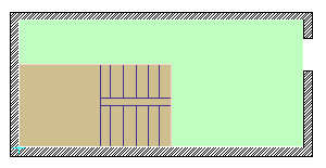
Use the GetArea command to calculate the area and perimeter by specifying a drawing entity or by specifying points that comprise an area to measure.
You can also use the Area option of the MeasureGeometry command.
You can add or subtract areas in a single operation.
The command calculates the following:
- Area, Perimeter, Length, or Circumference of an entity
- Areas defined by specifying points
- Combined areas
To calculate the area and perimeter of a drawing entity:
- Click Tools > Inquiry > Get Area (or type GetArea).
- Specify the Select Entity option.
Use this option to evaluate regular geometric areas (such as Circles, Ellipses, Arcs, or PolyLine contours). If you specify an entity that is not closed, the area is computed as if it is closed.
- In the graphics area, select a drawing entity.
The resulting measurements display. The displayed information depends on the type of the specified drawing entity. For example, for Circles and Ellipses the command displays area and circumference.
To calculate the area and perimeter by specifying points:
- Click Tools > Inquiry > Get Area (or type GetArea).
- In the graphics area, specify points that comprise an area to measure.
The defined area highlights dynamically in the graphics area as you specify points.
 If you want to use specific points from drawing entities, for instance, a start or end point of a drawing entity, use the EntitySnap functions.
 - Press Enter when you finish specifying points.
The area and perimeter measurements display.
To calculate combined areas:
You can calculate the total area of several combined regions by specifying points or by selecting entities. Define an area by specifying points or using the Specify Entity option. Continue adding or removing areas as needed using Add and Subtract options.
- Click Tools > Inquiry > Get Area (or type GetArea).
- Specify the Add or Subtract option to add or subtract a partial area.
- Specify points that comprise an area to measure and press Enter.
– or –
Specify the Select Entity option and select a drawing entity in the graphics area.
The area and perimeter measurements display.
- Repeat step 3 to add or subtract further areas.
The addition or subtraction operation is calculated and the area and perimeter measurements display.
When partial areas are added or subtracted from an area, the evaluated area is the new parameter value unless you explicitly specify a different option.
- Press Enter.
Access
Command: GetArea
Menu: Tools > Inquiry > Get Area
Ribbon: Home > Tools > Inquiry > Get Area
Ribbon: Manage > Utilities > Inquiry > Get Area
Measuring Geometries
Use the MeasureGeometry command to measure distances, radius, angles, and areas within a single command.
The MeasureGeometry command provides options that perform the same calculations as the following commands:
If the area you want to calculate has geometrically significant points, for example, start or end points of a drawing entity, use EntitySnaps.
To measure geometries:
- Click Tools > Inquiry > Measure Geometry (or type MeasureGeometry).
- Specify an option:
- Distance. Measures the distance between two specified points.
- Radius. Measures the radius of a specified arc, circle, or an arc segment of a PolyLine.
- Angle. Measures the angle corresponding to a specified arc or two specified line or polyline segments. The displayed measurements depend on the entity that you specify in the graphics area.
-
Area. Calculates the area and perimeter by specifying a drawing entity or by specifying points that comprise an area to measure in the same way as the GetArea command. The resulting measurements display also the perimeter for closed areas, the length for open PolyLine contours, and the circumference for Circles and Ellipses.
Specify an option:
-
Specify points. Calculates the area and perimeter defined by points that comprise the area to measure. The defined area highlights dynamically in the graphics area as you specify points.
- Specify Entity. Calculates regular geometric areas (such as Circles, Ellipses, Arcs, or PolyLine contours). If you specify an entity that is not closed, the area is computed as if it is closed.
-
Add. Turns on Add mode and calculates a total area as you specify partial areas by specifying points or using the Specify Entity option. The area and perimeter measurements display.
Example: Add areas of different shapes to determine the total area.
-
Subtract. Turns on Subtract mode and subtracts a specified area from the total area. The area and perimeter measurements display.
Example: Subtract the area consumed by the stairs from the area of the room.
Divide a shape into regular shapes and use Add and Subtract options to calculate the area during a single operation. -
Specify points. Calculates the area and perimeter defined by points that comprise the area to measure. The defined area highlights dynamically in the graphics area as you specify points.
Access
Command: MeasureGeometry
Menu: Tools > Inquiry > Measure Geometry
Ribbon: Home > Tools > Measure Geometry
Listing Entity Information
Use the GetProperties command to view details of an entity, including the entity’s type, Layer, LineColor, LineStyle, LineWeight, mode (model or sheet), its coordinates, and other details depending on its type. For example, GetProperties lists added details about an Arc include its center point, radius, and start and end angle. Added details about a Line include its length, angle in the XY-plane, delta-X, delta-Y, and delta-Z lengths.
To list entity information:
- Click Tools > Inquiry > Get Properties (or type GetProperties).
- In the graphics area, select entities.
- Press Enter.
The geometric details and properties of the entities display in a separate command history window.
Press F2 to show or hide the separate command history window.
Press F2 to show or hide the separate command history window.
Press Fn + F2 to show or hide the separate command history window.
Access
Command: GetProperties
Menu: Tools > Inquiry > Get Properties
Ribbon: Home > Properties > Get Properties
Ribbon: Manage > Utilities > Inquiry > Get Properties
Displaying Mass Properties of 3D Solids and Regions
The GetMassProperties command calculates and displays the mass properties of 3D solids and regions.
The command reports properties such as volume, bounding box, center of gravity, moments of inertia, and others for 3D solids, and area, perimeter, bounding box for regions.
To display mass properties of 3D solids or regions:
- Click Tools > Inquiry > Region/Mass Properties (or type GetMassProperties).
- Specify the entities to be analyzed.
- The properties display for each solid object or region on the separate command window.
- Mass properties include: mass, volume, bounding box, centroid, moments of inertia, products of inertia, radii of gyration, and principal moments and X-Y-Z directions about the centroid.
Access
Command: GetMassProperties
Menu: Tools > Inquiry > Region/Mass Properties
Ribbon: Home > Tools > Inquiry > Region/Mass Properties
Ribbon: Manage > Utilities > Inquiry > Region/Mass Properties
Using the SmartCalculator
Use the Smart Calculator palette to perform mathematical, scientific, trigonometric computations, and measurement conversions at any time.
In addition to the basic features, the palette includes tools for quick inquiries including distances between two points, total area of entities, angles, and circumference.
You can build expressions and edit them as necessary before calculating the result. To evaluate an expression, click the equal (=) sign, or press Enter. At any time, in the History area, you can review and retrieve previously calculated expressions.
You can do the following:
- Mathematical, scientific, and trigonometric calculations
- Review previously evaluated calculations
- Convert measurement units
- Geometric measurements
- Copy values and expressions to the clipboard
Use the SmartCalculator command to display the Smart Calculator palette.
You can expand or collapse each category. Also, you can resize the SmartCalculator in the same way you do with any other palettes.
To display the Smart Calculator palette:
- Type SmartCalculator at the command prompt.
The Smart Calculator Palette
The Smart Calculator palette contains the following areas:
- Calculation
- Number pad
- Scientific
- Measurement tools
- Unit conversion
Calculation
History area
Displays a list of previously evaluated expressions. You can clear the entire history or only a specified line.
- CH. Clears the History area.
- CR. Clears a row that you specified in the History area.
The context menu provides options for copying an expression or a value to the clipboard.
You can paste an expression or a value from the History list by double-clicking it.
Input field
Lets you type and retrieve expressions. You can either enter expressions using the Number pad buttons, or you can use the computer keyboard or numeric keypad. To evaluate an expression and display the result, click the equal (=) sign, or press Enter. The Smart Calculator evaluates expressions according to the standard mathematical rules of precedence.
In the Input field, the Smart Calculator displays values according to the following rules:
- Results of calculations are always expressed in decimal format with the precision specified in Drawing Settings.
Note: The display is limited to eight decimal places of precision.
- Results of angular calculations are always expressed in degrees with full precision.
- Angular values that you specify in the Input field are assumed to be degrees regardless of the settings specified in Drawing Settings.
Note: When using the keyboard, make sure the NumLock is on.
Copy buttons
- Copy to clipboard. Copies the value from the input field to the clipboard.
- Copy to command line. Pastes the value in the input field at the command prompt.
Memory tools
Groups tools for storing and retrieving values in the Smart Calculators memory.
| Button | Description |
|---|---|
| MS | Stores the value displayed in the Input field in the Smart Calculators memory. Smart Calculator overwrites the previous value, if there is any. |
| M+ | Adds the current value to the value stored in the Smart Calculators memory |
| M- | Subtracts the current value from the value stored in the Smart Calculators memory |
| MR | Restores the value saved in the Smart Calculators memory. Smart Calculator overwrites the value displayed in the Input field with the one stored in the memory. |
| MC | Clears the value stored in the Smart Calculators memory |
Number pad
Groups numbers, symbols, and functions that you can use for mathematical expressions similarly to a standard calculator keypad. To evaluate an expression, click the equal (=) sign, or press Enter.
Scientific
Groups advanced tools, such as trigonometric, logarithmic, and exponential functions usually associated with scientific and engineering applications.
Measurement tools
Groups functions for quick inquiries, such as distances between two points, angle between two line or polyline segments, total area of entities, and circumference.
Measurement tools let you extract geometrical information such as, distance, angle, area, and circumference from the drawing entities. The result automatically appears in the input field, so that you can perform mathematical operations on the calculated value. Moreover, you can paste the calculated value at the command prompt.
| Icon | Name | Description |
|---|---|---|
 |
Measure distance | Measures the distance between two points |
 |
Measure angle | Measure angles between two line or polyline segments |
 |
Measure area | Calculates the area of defined areas |
 |
Measure circumference | Calculates the perimeter of entities or of defined areas |
Unit conversion
Unit conversions are available for length, area, volume, and angular values. Based on the unit type that you select, you can choose a list of units to convert from and a list of units to convert to.
Examples of Using the Smart Calculator
To use calculated values from the clipboard:
For example, draw a circle that has a radius 2/3 longer than 10 units.
- In the Input field, type 10*2/3 and press Enter. The calculated value displays.
- Start the Circle command and specify the center.
- In Smart Calculator, click Copy to commandline.
The value appears at the command prompt for specifying the radius.
- Press Enter.
To convert measurement units:
- Type SmartCalculator.
- Under Units Conversion:
- Select a Units type.
- Select the unit you want to Convert from.
- Select the unit you want to Convert to.
- Type the Value to convert.
- Click Evaluate
 .
. - The result displays in Converted value.
To measure the angle between two lines:
- On the Smart Calculator palette, in Measurement Tools, click Measure angle.
- In the graphics area, specify two line or polyline segments. Use entity snaps to ensure precision.
The input field displays the value of the angle between the two specified line or polyline segments.
To measure the distance between two points using the SmartCalculator:
- On the Smart Calculator palette, in Measurement Tools, click Measure distance.
- In the graphics area, specify two points. Use entity snaps to ensure precision.
The input field displays the value of the distance between the two specified points.
Use the Copy to command line option to paste the calculated value at a command prompt.
Access
Command: SmartCalculator
Ribbon: Manage > Utilities > Smart Calculator
Invoking the Standard OS Calculator
Use the OSCalc command to display the standard OS calculator.
To use the standard OS calculator:
- Click View, Standard or Scientific to set the mode.
- To copy the result of a calculation, click Ctrl + C.
- To paste the result to the command window, click Ctrl + V.
- Click View, Standard or Scientific to set the mode.
- To copy the result of a calculation, click Ctrl + C.
- To paste the result to the command window, click Ctrl + V.
- Perform a calculation using the calculator buttons.
- To copy the result of a calculation, click Command + C.
- To paste the result to the command window, click Command + V.
Access
Command: OSCalc