
Introduction
There are several dimension tools to display entity measurements or relations between entities.
By default, Dimensions are related to entities. If you modify an entity’s geometry, the Dimensions update to reflect the changes.
Dimensions usually consist of:
- A dimension line or arc.
- Extension lines extending to the measured entity.
- Dimension text.
Ordinate Dimensions, Leaders, and geometric tolerances consist of Dimension text and a Leader line.
Dimensions are based on DimensionStyles. DimensionStyles are a named set of defaults that adopt the requirements of specific industries or applications.
For more details about Associative Dimensions and the Annotation Monitor, see Working with Dimensions.
This section begins with basics about working with Dimensions:
You can change the appearance of Dimensions using DimensionStyles:
You can create the following Dimensions:
The following features annotate the drawing rather than reflect the geometric Dimensions of entities:
You can modify the appearance of Dimensions:
- Modifying Dimensions
- Overriding DimensionStyle Parameters
- Updating Dimensions
- Relate Dimensions
- Edit Tolerance
Working with Dimensions
There are several dimension tools to display entity measurements and relations between entities.
Elements of a Dimension
Dimensions usually consist of:
- A dimension line or arc.
- Extension lines extending to the measured entity.
- Dimension text.
Ordinate Dimensions, Leaders, and geometric tolerances consist of:
- Dimension text
- Leader line
Dimensions are based on DimensionStyles. DimensionStyles are a named set of defaults that adopt the requirements of specific industries or applications.
Associative Dimensions
By default, Dimensions are related to entities. If you modify an entity’s geometry, the Dimensions automatically adjust their location, orientation, and measurements values to reflect the changes.
The Associative property on the Properties palette shows whether a dimension is associative or non-associative.
As the project evolves, changes may cause the loss of the associativity between Dimensions and their related entities. At any time, you can reestablish the relation of Dimensions to entities using the RelateDimensions command.
 Use the Annotation Monitor to identify dimensions that have lost their associativity with related entities.
To control dimensions associativity with related entities:
- Do one of the following:
-
Click Tools > Options (or type Options).
Click Application menu > Preferences (or type Options).
In the Options dialog box, click Drawing Settings
 .
. - Type DrawingSettings.
-
- Expand Behavior and select or clear Enable relative dimensions.
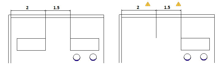
The Annotation Monitor
The Annotation Monitor tracks dimensions and annotations that loose the associativity to their related entities and marks them with an icon ![]() .
.
Clicking the icon displays a menu with options that are available for the non-associated dimension.
| Option |
Description |
|---|---|
| Reassociate | Lets you reassociate the annotation or dimension with the corresponding entities. Specify the point the dimension should relate with. |
| Delete | Deletes the annotation or dimension |
Example:
In the following example, a dimensioned entity is deleted. The Annotation Monitor displays an alert.
To turn on the Annotation Monitor:
- On the status bar, click AMonitor.
Formatting Dimensions
This chapter discusses:
This chapter discusses:
Section Contents
Working with Dimension Styles
Use the DimensionStyle command to create and modify DimensionStyles.
DimensionStyles control the way Dimensions look.
You can define Dimension Styles to apply annotative scaling for Dimensions.
To enable the Dimension Styles Manager, make sure the DIMSTYLEDLGMODE system variable is set to 1. Otherwise, the DimensionStyle command opens the Dimension category on the Drafting Styles page of the Options dialog box.
Managing Dimension Styles
To create a new Dimension Style:
- Click Format > Dimension Style (or type DimensionStyle).
- In the Dimension Style Manager dialog box, select a Dimension Style.
- Click New.
- In the Create new Dimension Style dialog box:
- For Name, type a value.
- In Based on, select an existing Dimension Style. This style serves as the base settings for the new Dimension Style.
- In Apply to, select a Dimension type. This specifies that the new Dimension Style is valid for all Dimensions or for a specific type of dimensioning.
- Click Next.
- In the Create New Dimension Style dialog box, set up the DimensionStyle. See Dimension Style Settings below.
- Click OK.
To modify a Dimension Style:
- Click Format > Dimension Style (or type DimensionStyle).
- In the Dimension Style Manager dialog box, select a Dimension Style to modify.
- Click Edit. See DimensionStyle Settings below.
- Click OK.
To set the active Dimension Style:
- Click Format > Dimension Style (or type DimensionStyle).
- In the Dimension Style Manager dialog box, select a DimensionStyle to activate.
- Click Activate.
 displays beside the active Dimension Style.
 - Click OK.
To compare Dimension Styles:
- Click Format > Dimension Style (or type DimensionStyle).
- In the Dimension Style Manager dialog box, click Differences.
- In the Find Differences in DimensionStyles dialog box, in Compare and To, select a DimensionStyle.
The DimensionStyle settings that differ are listed in the dialog box.
- Click Copy to copy the differences, or click Close.
- Click Close.
To override DimensionStyle settings:
You can temporarily change settings of the active DimensionStyle. These changes do not modify the DimensionStyle settings. The overriding settings can be applied as long as no other DimensionStyle is set as active.
- Click Format > Dimension Style (or type DimensionStyle).
- In the Dimension Style Manager dialog box, select a Dimension Style to override.
- Click Activate.
- Click Set Overrides.
- Set Dimension Style overrides. See DimensionStyle Settings below.
- Click OK.
To rename a DimensionStyle:
- Click Format > Dimension Style (or type DimensionStyle).
- In the Dimension Style Manager dialog box, select a Dimension Style to rename.
- Click Rename.
- In the Rename DimensionStyle dialog box specify a new name for the selected DimensionStyle and click OK.
![]() Alternatively, double-click a Dimension Style on the Styles list to rename it.
Alternatively, double-click a Dimension Style on the Styles list to rename it.
To delete a DimensionStyle:
- Click Format > Dimension Style (or type DimensionStyle).
- In the Dimension Style Manager dialog box, select a DimensionStyle to delete.
- Click Delete.
Confirm the deletion of the selected DimensionStyle. You cannot delete the Dimension Style named Standard or Dimension Styles referenced in the drawing by Dimension entities.
![]() You can remove Dimension Styles that are not referenced in the drawing with the Clean command.
You can remove Dimension Styles that are not referenced in the drawing with the Clean command.
DimensionStyle Settings
You can modify DimensionStyles using the settings in the Create New Dimension Style dialog box for new Dimension Styles, and in the Edit Dimension Style dialog box for existing Dimension Styles.
Lines
Lets you modify the display settings for Dimension lines.
Dimension line settings
- Style: Sets the Dimension line LineStyle.
- Weight: Sets the Dimension line LineWeight.
- Color: Sets the Dimension line LineColor.
- Offset: Sets the offset distance of Dimension lines when baseline dimensioning is applied using the BaselineDimension command.
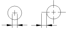
- Distance past start arrow: Sets a distance to extend the Dimension line beyond the extension line when you apply certain arrowheads such as tick or architectural.
-
Hide:
- Dimension line 1: Determines whether the first Dimension line and arrowhead between the first extension line and the Dimension text is displayed.
- Dimension line 2: Has the same effect as Dimension line 1 for the second extension line and Dimension text.
Extension line settings
Extension lines are the lines that extend the Dimension outside the perimeter of the measured entity, assuming that dimensioning is to take place outside of these perimeter constraints.
- Styles: Sets the LineStyle for Extension line 1 and Extension line 2.
- Weight: Sets the extension line LineWeight.
- Color: Sets the extension line LineColor.
- Distance past dimension lines: Sets the distance the extension lines should run past the Dimension lines.
- Hide: Hides the first and/or second extension line.
- Offset: Sets the offset distance between the entity and the point where extension lines begin.
- Fixed length: Specifies whether extension lines should have a preset length. Set a value in Length.
Symbols & Arrows
Lets you modify the appearance of symbols and arrows.
Arrows
- Start arrow: Specifies the Dimension’s starting arrowhead.
- End arrow: Specifies the Dimension’s ending arrowhead.
- Leader arrow: Sets the Dimension’s leader arrow style.
- Size: Sets the arrowhead size.
Note: For any arrow, you can use an existing Block as arrowhead. Select the Custom arrow option from the drop-down list and specify the Block from the Select Custom Arrow dialog box.
Radius dimension jog
- Angle: Determines the angle of the transverse segment of the dimension line in a jogged radius Dimension.
- Gap: Specifies the width of the default gap when you use the SplitDimension command to split dimension and extension lines which cross other entities.
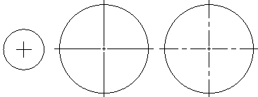
Center mark display
-
None, As mark, As centerline: Defines the display of marks that indicate a Circle’s center point and defines whether or not dashes or strokes should be added to center marks.


As mark As centerline (accordig to the drawing standard)
As mark As centerline (accordig to the drawing standard)
-
Size: Lets you specify the size of the center mark or the length of the extension lines, according to the selected center mark display for center, diameter, and radius Dimensions.
As mark (size) As centerline (length of the extension line)
Arc length symbols
Lets you set the display of a symbol for arc length Dimensions: Before dimension text, Above dimension text, or None.
Text
Lets you modify the display of text for Dimensions.
Text settings
-
Style: Sets the Dimension TextStyle. Click
 to define TextStyles.
 - Color: Sets the Dimension TextColor.
- Fill: Sets the Dimension text background color.
- Height: Sets the Dimension text height.
- Fractional scale: Sets a scale factor for the text height of tolerance values relative to the general Dimension text height.
- Frame dimension text: Draws a frame around Dimension text.
Text position
- Horizontal and Vertical: Sets the horizontal and vertical positions of the Dimension text.
- Offset from dimension lines: Sets the distance that text is offset from the Dimension lines.
Text alignment
You can align the Dimension text with the following options:
- Use ISO standard
- Align horizontally
- Align with dimension lines
Fit
Fit options determine how to arrange Dimensions if there is not enough space for text and arrows between the extension lines.
Geometry
-
When space is limited, move selected entity outside of extension lines: When there is not enough room to place text and arrows inside the extension lines, the first entity to move outside the extension lines is:
- Automatic: Either text or arrows (best fit)
- Arrows
- Text
- Text and arrows
- Keep text between extension lines
- Hide arrows: Suppresses arrows if they do not fit inside the extension lines.
Dimension scale
-
Annotative Scaling: Specifies whether annotative scaling is used for Dimensions which apply the DimensionStyle you define. In Style, annotative DimensionStyles are marked with an
 icon.
icon. -
Scale factor: Specifies the overall scale for DimensionStyle settings. The scale factor influences size, distance, and spacing, including text and arrowhead sizes.
This option is available only if you selected annotative scaling for the DimensionStyle.
-
Scale dimensions according to sheet: Sets a scale factor based on the ratio between the current Viewport and the drawing Sheet.
This option is available only if you selected annotative scaling for the DimensionStyle.
Dimension text
-
When dimension text is not in the default position, move it: When Dimension text is not in the default position, you can place it:
- Above the dimension line with leader
- Above the dimension line without leader
- Next to the dimension line
Additional options
- Dimension lines between extension lines: Forces dimension lines to remain between the extension lines, even if the arrowheads are generated outside the Dimension.
- Specify text placement: Lets you position Dimension text manually; horizontal justification settings are ignored.
Primary units
Lets you modify the display of primary units for Dimensions.
Linear Dimension
- Format: Sets the primary linear units format.
- Precision: Sets the number of decimal places.
- Fractional display: Sets the stack display of fractional units.
- Decimal separator: Sets the decimal separator for Dimensions whose unit Format is set to Decimal.
- Round to the nearest: Lets you specify a value for rounding.
- Prefix and Suffix: Lets you type a character string to appear before or after the Dimension text. For example, the suffix field can display the unit of measurement.
-
Measurement scale:
- Scale factor: Forces all linear Dimension texts (including the Dimension text of diameters, radii, and coordinates) to be multiplied with the specified scale factor. Angular Dimensions and the plus-/minus values of Tolerances are not affected. The setting applies especially for non-associative dimensioning (for example, when you dimension scaled details).
- Follow sheet dimensions: Applies the measurement scale factor to Dimensions created on Sheets only.
-
Zeroes display:
- Hide leading zeroes and Hide trailing zeroes: Lets you suppress leading and trailing zeroes in decimal linear Dimensions.
- Hide if 0′ and Hide if 0": If you set Format to Architectural or Engineering, you can also specify whether to hide zero feet (Hide if 0′) and zero inches (Hide if 0″)
Angular dimension settings
- Format: Sets the primary angular units format (Decimal Degrees, Deg/Min/Sec, Grads, or Radians).
- Precision: Sets the number of decimal places.
- Zeroes display: Lets you suppress leading and trailing zeroes in angular Dimensions.
Alternate Units
These options control the use of a second, alternative dimensioning method. This mode allows dual dimensioning in metric and imperial values.
- Show alternate dimensions: Determines whether to use alternate units in Dimensions.
-
Alterbate dimension settings
- Format: Sets the alternate unit format.
- Precision: Sets the number of decimal places.
- Multiplier for converting units: Sets a multiplier for converting units.
- Round to the nearest: Lets you specify a value for rounding.
- Prefix and Suffix: Lets you specify a prefix and suffix for the Dimension value.
-
Zeroes display
- Hide leading zeroes and Hide trailing zeroes: Lets you suppress leading and trailing zeroes.
- Hide if 0′ and Hide if 0": If you set Format to Architectural, Architectural Stacked, or Engineering, you can also specify whether to hide zero feet and zero inches.
-
Insertion
- Below primary units and After primary units: Specifies whether alternate units are placed after or below the primary Dimension value.
Tolerance
Lets you modify tolerance for Dimensions.
Tolerance settings
-
Calculation: Sets the format for tolerance creation:
- Basic: Displays the additional Dimension measurement and deviation in a single value with a box around it.
- Deviation: Appends separate plus and minus values of deviation to the Dimension measurement.
- Limits: Displays a maximum and a minimum value, one on top of the other.
- None: Does not generate a tolerance value.
- Symmetrical: Appends a plus/minus tolerance value to the Dimension measurement which indicates the positive and negative deviation in a single value.
- Precision: Sets the number of decimal places.
- Maximum value and Minimum value: Sets values for the positive or negative tolerances.
- Scale: Sets the tolerance scale.
- Vertical text justification: Sets the tolerance text justification.
-
Zeroes display:
- Hide leading zeroes and Hide trailing zeroes: Lets you suppress leading and trailing zeroes in decimal tolerance Dimensions.
- If you set the Format for Linear Dimension to Architectural or Engineering, you can also specify whether to hide zero feet (Hide if 0′) and zero inches (Hide if 0″).
Alternate units
- Precision: Sets the number of decimal places for alternate Dimensions in geometric tolerances.
-
Zeroes display:
- Hide leading zeroes and Hide trailing zeroes: Lets you suppress leading and trailing zeroes in decimal alternate Dimensions.
- If you set the Format for Linear Dimension to Architectural or Engineering, you can also specify whether to hide zero feet (Hide if 0′) and zero inches (Hide if 0″).
Access
Command: DimensionStyle
Menu: Format > Dimension Style
Ribbon: Home > Annotations > Dimension Style 
Editing and Formatting Dimension Text
Several dimensioning commands allow you to edit or format the Dimension text while creating Dimensions.
The ParallelDimension command is an example of such a command. After you either specify two defining points or identify an entity to be dimensioned, you are prompted to specify the dimension line location. This is when you can specify the Note, Text, or Angle option to edit the Dimension text before being prompted to specify the dimension line location again:
Options: Angle, Note, Text or
Specify dimension line position»
Options: Angle, Text or
Specify dimension line position»
Dimension Text Editing Options
Angle
The Angle option changes the angle of the Dimension text.
You are prompted to specify the angle of the Dimension text. Type the rotation angle.
By using the entity snap functions, you can align the Dimension text to the entity that is measured.
For example, you can align the Dimension text of a parallel Dimension (which is usually created with a zero° angle) to the dimension line by snapping to its end points.
Note
The Note option lets you change the Dimension text using the multiline text editor in the Edit Note dialog box.
You can change the Text or add Text. You can control codes and Unicode character strings to add special characters or symbols. The Special Characters list contains a number of these special characters (degrees, diameter, plus/minus, not equal, etc.)
You can also change the font, modify the typeface (bold, italic), or underline the Dimension.
Text
The Text option lets you change the Dimension text.
To maintain the generated measurement in your text string, use angle brackets (<>) to represent it. For example, if you want to change the generated measurement "2.54" to "approx. 2.54", type "approx. <>" at the prompt to enter Dimension text.
Creating Dimensions
This chapter discusses:
This chapter discusses:
Section Contents
- Using Smart Dimensions
- Creating Linear Dimensions
- Creating Parallel Dimensions
- Creating Arc Length Dimensions
- Creating Ordinate Dimensions
- Creating Radius Dimensions
- Creating Jogged Dimensions
- Creating Diameter Dimensions
- Creating Angular Dimensions
- Creating Baseline Dimensions
- Creating Continuous Dimensions
Using SmartDimensions
Use the SmartDimension command to create Dimensions by specifying entities.
You can apply the command to Lines, PolyLine segments, Arcs, Circles, and Rings:
- For linear entities parallel to an axis of the coordinate system, aligned Dimensions (parallel Dimensions) are created. For linear entities not parallel to an axis of the coordinate system, either aligned Dimensions (measuring the absolute distance between two points) or horizontal or vertical Dimensions (measuring the horizontal or vertical distance between two points) depending on where you move the pointer are created.
- For curved entities, you can create radial, diameter, linear, angular, and arc length Dimensions.
If you select a Dimension in the graphics area and the ribbon is active, the corresponding Dimension Selection contextual ribbon tab appears. The contextual ribbon tab groups options and tools for controlling the DimensionStyle, arrows, and dimension lines.
To dimension entities:
- Click Dimension > Smart (or type SmartDimension).
- In the graphics area, select an entity to dimension.
- Specify the position of the dimension line.
To use another dimension type for Circles or Arcs, specify an option:
- Diameter. Creates a diameter Dimension.
- Radial. Creates a radial Dimension for an Arc or Circle.
- Linear. Creates a linear Dimension of the diameter of a Circle or an aligned, horizontal, or vertical Dimension between the end points of an Arc.
- Angular. Dimensions the angle between the end points of an Arc.
-
Arc length. Dimensions an Arc length.
Note: The chosen option is the default the next time you use the SmartDimension command.
When you move the pointer during a linear dimensioning, you can:
- Lock. Determines the current dimension type (aligned, horizontal, or vertical) regardless where you move the pointer.
- Unlock. Unlocks the type of linear dimension used.
- Press Enter.
Use the ContinueDimension command to create linear dimension chains.
Access
Command: SmartDimension
Menu: Dimension > Smart
Ribbon: Annotate > Dimensions > Smart
Creating Parallel Dimensions
The ParallelDimension command creates aligned linear Dimensions.
Parallel dimensioning is a type of linear dimensioning that measures and labels the absolute distance between two points, regardless of the relative position of the axes. This lets you dimension Lines, edges, or spaces that are not located on the principal axes of the coordinate system, that is, not parallel to X-, Y- or Z-axes of the coordinate system.
If you select a Dimension in the graphics area and the ribbon is active, the corresponding Dimension Selection contextual ribbon tab appears. The contextual ribbon tab groups options and tools for controlling the DimensionStyle, arrows, and dimension lines.
To create parallel Dimensions:
- Click Dimension > Aligned (or type ParallelDimension).
- Specify the first and second extension line origins.
– or –
Press Enter, then specify an entity to dimension. You can specify Lines, PolyLines, Circles, and Arcs. With Lines, PolyLines, and Arcs, the start and end points of the entity are measured. With Circles, the diameter is measured. The pick point on the Circle is used as start point of the first extension line along the perimeter of the Circle.
- In the graphics area, specify the position of the dimension line or use the Angle, Note, or Text options. See Editing and Formatting Dimension Text.
The measurement is placed as Dimension text based on the definitions of the current DimensionStyle.
Access
Command: ParallelDimension
Menu: Dimension > Aligned
Ribbon: Annotate > Dimensions > Dimension > Parallel
Creating Linear Dimensions
The LinearDimension command creates horizontal, vertical, and rotated linear Dimensions.
If you select a Dimension in the graphics area and the ribbon is active, the corresponding Dimension Selection contextual ribbon tab appears. The contextual ribbon tab groups options and tools for controlling the DimensionStyle, arrows, and dimension lines.
To create linear Dimensions:
- Click Dimension > Linear (or type LinearDimension).
- Specify the first and second extension line origins.
– or –
Press Enter, and specify an entity to dimension. You can specify Lines, PolyLines, Circles, and Arcs. The start and end points of linear entities, or the diameter of circular entities are measured.
- Specify the position of the dimension line or specify an option:
- Angle, Note, or Text: See Editing and Formatting Dimension Text. To dimension the real length of Lines not parallel to the X- or Y-axis of the coordinate system, use the ParallelDimension command.
- Horizontal: Creates a horizontal linear Dimension. The horizontal distance between the defining points is measured and the dimension line is parallel to the X-axis.
- Rotated: Creates an oblique Dimension about an angle you specify for the dimension line. The distance between the defining points is measured along the specified rotation (parallel to the oblique dimension line).
- Vertical: Creates a vertical linear Dimension. The vertical distance between the defining points is measured and the dimension line is parallel to the Y-axis.
The measurement is placed as Dimension text based on the definitions of the current DimensionStyle.
Access
Command: LinearDimension
Menu: Dimension > Linear
Ribbon: Annotate > Dimensions > Dimension > Linear
Creating Arc Length Dimensions
The ArcLengthDimension command creates an arc length Dimension. It measures the distance along an Arc or Arc segment of a PolyLine.
To differentiate arc length Dimensions from linear or angular Dimensions, an arc symbol is displayed with the Dimension text.
The arc symbol is displayed before or above the Dimension text depending on the current DimensionStyle.
If you select a Dimension in the graphics area and the ribbon is active, the corresponding Dimension Selection contextual ribbon tab appears. The contextual ribbon tab groups options and tools for controlling the DimensionStyle, arrows, and dimension lines.
To create arc length Dimensions:
- Click Dimension > Arc Length (or type ArcLengthDimension).
- In the graphics area:
- Select an Arc or Arc segment of a PolyLine.
- Specify the position of the dimension line or specify an option:
- Angle, Note, or Text: See Editing and Formatting Dimension Text.
- Leader. Adds a Leader to the Dimension which is drawn from the dimension line to the Arc towards the center of the Arc. A Leader is added only if the included angle of the Arc is less than 90°. The command creates the Leader automatically. You must specify the location of the dimension line. The No leader option exits the Leader option and lets you conclude the command without creating a Leader.
- Partial. Lets you dimension the length of part of an Arc. Specify two points on the Arc: one where the arc length Dimension should begin, and another where it should end. Use the EntitySnap functions to ensure that the two points are located on the Arc.
Access
Command: ArcLengthDimension
Menu: Dimension > Arc Length
Ribbon: Annotate > Dimensions > Dimension > Arc Length
Creating Ordinate Dimensions
The OrdinateDimension command creates ordinate point Dimensions.
The command displays an X or Y coordinate with a Leader line to create X-datum or Y-datum dimensioning. The value of the X or Y coordinate is defined by the point you specify, called the feature location.
If you select a Dimension in the graphics area and the ribbon is active, the corresponding Dimension Selection contextual ribbon tab appears. The contextual ribbon tab groups options and tools for controlling the DimensionStyle, arrows, and dimension lines.
To create ordinate Dimensions:
- Click Dimension > Ordinate (or type OrdinateDimension).
- In the graphics area, specify the feature location (the point to be measured).
Use EntitySnaps if the location represents a specific geometric point of an entity (such as the center of a Circle).
- Specify a Leader end point or specify an option:
- Xdatum. Measures the X ordinate regardless of where you set the Leader end point. The option determines the orientation of the Leader line and Dimension text.
- Ydatum. Measures the Y ordinate regardless of where you set the Leader end point. The option determines the orientation of the Leader line and Dimension text.
- Set Zero. The specified datum position determines the base point from which all other ordinate dimensions applying the Reference option are measured. The option creates a 0.00 ordinate dimension at the position you specify in the graphics area.
- Reference. The specified datum position is measures the X or Y ordinate relative to the zero position specified with the Set Zero option. The option creates the referenced ordinate dimension at the position you specify in the graphics area.
- Angle, Note, or Text. See Editing and Formatting Dimension Text.
The leader end point also determines the location of the measurement value Text. The Leader originates at the point to be measured and connects to the Dimension text.
If the Dimension is not placed horizontally or vertically in relation to the measured point, the extension line appears in orthographic mode and not as a straight line.
Access
Command: OrdinateDimension
Menu: Dimension > Ordinate
Ribbon: Annotate > Dimensions > Dimension > Ordinate
Creating Radius Dimensions
The RadiusDimension command creates radial Dimensions for Circles and Arcs.
Radius dimensioning is done the same way as diameter dimensioning.
The appearance depends on the settings of the current DimensionStyle.
If you select a Dimension in the graphics area and the ribbon is active, the corresponding Dimension Selection contextual ribbon tab appears. The contextual ribbon tab groups options and tools for controlling the DimensionStyle, arrows, and dimension lines.
To create radius Dimensions:
- Click Dimension > Radius (or type RadiusDimension).
- In the graphics area:
- Select an Arc or Circle.
- Specify the location of the dimension line or specify an option:
Angle, Note, or Text: See Editing and Formatting Dimension Text.
Access
Command: RadiusDimension
Menu: Dimension > Radius
Ribbon: Annotate > Dimensions > Dimension > Radius
Creating Jogged Dimensions
The JoggedDimension command creates jogged radius Dimensions for Circles and Arcs.
Jogged dimension lines are typically used when a sheet is too small to display the true center point of radial Dimensions. The command lets you specify another origin point for the dimension line. This point is called the center position override.
The command measures the radius of the specified Circle or Arc and displays the Dimension text with a preceding radius symbol.
If you select a Dimension in the graphics area and the ribbon is active, the corresponding Dimension Selection contextual ribbon tab appears. The contextual ribbon tab groups options and tools for controlling the DimensionStyle, arrows, and dimension lines.
To create jogged Dimensions:
- Click Dimension > Jogged (or type JoggedDimension).
- In the graphics area:
- Select an Arc or Circle.
- Specify a point for the center position override.
- Specify the position of the dimension line or specify an option:
Angle, Note, or Text: See Editing and Formatting Dimension Text.
- Specify a jog position.
Access
Command: JoggedDimension
Menu: Dimension > Jogged
Ribbon: Annotate > Dimensions > Dimension > Jogged
Creating Diameter Dimensions
The DiameterDimension command creates diameter Dimensions for Circles and Arcs.
Unlike linear or parallel dimensioning applied to Circles (which also display the diameter), no measurement lines display. The command creates a single dimension line to show the relationship between the value and the entity.
The appearance depends on the settings of the current DimensionStyle.
If you select a Dimension in the graphics area and the ribbon is active, the corresponding Dimension Selection contextual ribbon tab appears. The contextual ribbon tab groups options and tools for controlling the DimensionStyle, arrows, and dimension lines.
To create diameter Dimensions:
- Click Dimension > Diameter (or type DiameterDimension).
- In the graphics area:
- Select a Circle or an Arc.
- Specify the position of the dimension line or specify an option:
Angle, Note, or Text: See Editing and Formatting Dimension Text.
Access
Command: DiameterDimension
Menu: Dimension > Diameter
Ribbon: Annotate > Dimensions > Dimension > Diameter
Creating Angular Dimensions
Use the AngleDimension command to dimension angles in a drawing.
You can create angular Dimensions formed:
- Freely by a vertex and two points on the legs
- By two Lines
- By the two end points of an Arc
- By any two points on the perimeter of a Circle.
The command lets you create the dimension of the interior angle between the two legs and the exterior angle.
If you select a Dimension in the graphics area and the ribbon is active, the corresponding Dimension Selection contextual ribbon tab appears. The contextual ribbon tab groups options and tools for controlling the DimensionStyle, arrows, and dimension lines.
To create angular Dimensions for Lines:
- Click Dimension > Angular (or type AngleDimension).
- Specify the first and second Lines in the graphics area.
When you move the pointer between the two Lines, the preview shows the inner angle Dimension. When you move the pointer outside the two Lines, the preview shows the outer angle Dimension.
- Click in the graphics area to place the dimension arc lines or specify an option:
Angle, Note, or Text: See Editing and Formatting Dimension Text.
The position determines whether the inner or outer angle is measured.
To create angular Dimensions for Arcs:
- Click Dimension > Angular (or type AngleDimension).
- Select an Arc in the graphics area.
- Click in the graphics area to place the dimension arc lines or specify an option:
Angle, Note, or Text: See Editing and Formatting Dimension Text.
The angular Dimension appears between the end points of the Arc with the center point of the Arc as vertex.
To create angular Dimensions for Circles:
- Click Dimension > Angular (or type AngleDimension).
- Select a Circle in the graphics area. The point you specify determines the first leg of the angle.
Use EntitySnaps to define the points on the perimeter of the Circle.
- Select the second angle point. This defines the angle with the center point of the Circle as the vertex.
- Click in the graphics area to place the dimension arc lines or specify an option:
Angle, Note, or Text: See Editing and Formatting Dimension Text.
To create angular Dimensions for vertices:
- Click Dimension > Angular (or type AngleDimension).
- Press Enter to specify vertex.
- Select an angle vertex in the graphics area.
- Select two other points to define the angle.
- Click in the graphics area to place the dimension arc lines or specify an option:
Angle, Note, or Text: See Editing and Formatting Dimension Text.
The position determines whether the inner or outer angle is measured.
To create an angular Dimension formed by two points on the perimeter of an Arc, specify the Vertex option using EntitySnaps to define the center point and two points on the perimeter of the Arc.
Access
Command: AngleDimension
Menu: Dimension > Angular
Ribbon: Annotate > Dimensions > Dimension > Angular
Creating Baseline Dimensions
The BaselineDimension command creates a series of parallel linear Dimensions that share the same baseline. Baseline dimensioning allows you to read the cumulative Dimension between two end points extending over a number of individual Dimensions within a chain.
This type of dimensioning assumes that a related linear, angular, or ordinate Dimension exists in the drawing.
If you select a Dimension in the graphics area and the ribbon is active, the corresponding Dimension Selection contextual ribbon tab appears. The contextual ribbon tab groups options and tools for controlling the DimensionStyle, arrows, and dimension lines.
To create baseline Dimensions:
- Ensure that the entity you want to dimension already has a linear, angular, or ordinate Dimension to serve as the base Dimension, or insert a Dimension if necessary.
- Click Dimension > Baseline (or type BaselineDimension).
When the last dimensioning command created a linear, angular, or ordinate Dimension, you are prompted to select a point as the second extension line origin. In other cases, you are prompted to select an existing linear, angular, or ordinate Dimension as the base Dimension.
The same request appears if you press Enter to specify a second extension line origin.
- In the graphics area, select the:
- Second extension line origin or a baseline Dimension (linear, angular, or ordinate Dimension) depending on the command prompt.
- Points for subsequent extension line origins. Use EntitySnaps for ease of dimensioning.
When creating linear baseline Dimensions, each Dimension displays the distance between the baseline and the point you select.
- If necessary, specify the Undo option to remove the last continuous Dimension created during the current command.
Access
Command: BaselineDimension
Menu: Dimension > Baseline
Ribbon: Annotate > Dimensions > (Flyout) Baseline
Creating Continuous Dimensions
The ContinueDimension command continues a linear, angular, or ordinate Dimension from an extension line of the previous or specified Dimension.
If you select a Dimension in the graphics area and the ribbon is active, the corresponding Dimension Selection contextual ribbon tab appears. The contextual ribbon tab groups options and tools for controlling the DimensionStyle, arrows, and dimension lines.
To create continuous Dimensions:
- Ensure that the entity you want to dimension already has a linear, angular, or ordinate Dimension, or insert a Dimension if necessary.
- Click Dimension > Continue (or type ContinueDimension).
When the last dimensioning command created a linear, angular, or ordinate Dimension, you are prompted to select a point as the second extension line origin. In other cases, you are prompted to select an existing linear, angular, or ordinate Dimension as the base Dimension.
The same request appears if you press Enter at the prompt to specify a second extension line origin.
- In the graphics area, select the:
- Second extension line origin or a baseline Dimension (linear, angular, or ordinate Dimension) depending on the command prompt.
- Points for subsequent extension line origins. Use EntitySnaps for ease of dimensioning.
When creating linear continuous dimension chains, the Dimension text displays the distance between the extension line you append to and the point you select.
- If necessary, specify the Undo option to remove the last continuous Dimension created during the current command.
Access
Command: ContinueDimension
Menu: Dimension > Continue
Ribbon: Annotate > Dimensions > (Flyout) Continue
Working with Leaders, Center Marks, and Geometric Tolerances
Use leader commands to draw leader lines that connect annotations to drawing entities.
You can create:
- SmartLeaders. SmartLeaders are Leader lines that connect annotations to a drawing entity. Additional formatting features are available.
- Leader Lines. Leader lines are lines that connect annotations to a drawing entity
You can create geometric tolerances to place datum feature symbols and datum targets in drawings.
This section discusses:
- Creating SmartLeaders
- Creating Leader Lines
- Creating Center Marks
- Creating Geometric Tolerances
- Editing Geometric Tolerances
Creating SmartLeaders
Use the SmartLeader command to draw Leader lines that connect annotations to a drawing entity.
Leaders are useful when the Dimension text or annotation does not fit next to the corresponding drawing entity. You can optionally place single or multiple lines of Text, a geometric tolerance, a Block Reference, or a copy of another Leader at the end point of the leader line.
Draw Leaders as straight line segments or spline curves. By default, the start point of a Leader is an arrowhead you can customize.
You can also use the Leader command to create a Leader. The SmartLeader command provides additional formatting features.
If you select a SmartLeader in the graphics area and the ribbon is active, the Leader Selection contextual ribbon tab appears. The contextual ribbon tab groups options and tools for controlling the LeaderStyle, arrows, and leader lines.
To create Leader lines:
- Click Dimension > Leader (or type SmartLeader).
- Enter the first leader point or optionally press Enter to use the Format Leaders dialog box to customize the Leader settings. To customize the annotated Text, use the Annotations tab of the dialog box:
- Click the Type of annotated Text:
- Block. Prompts for a Block insertion to be appended to the Leader after you specify its vertices.
- Copy entity. Lets you specify a single or multiple line Text, a Block, or a geometric tolerance to append at the end of the Leader after you specify its vertices.
- Note. Prompts to enter annotation text and lets you invoke the Note Formatting pop-up toolbar to enter and format the annotation.
- Tolerance. Lets you create a feature control frame for tolerances at the end of the Leader using the Geometric Tolerance dialog box.
- None. Creates the Leader with no annotation so you can draw a Leader line from one drawing entity to another.
- In Note options, customize the display for annotations when you use the Note option:
- Left justify. If left justifying, you do not enter a line width. The text lines you enter can be of any length without any automatic line break.
- Specify width. Prompts for the width of the annotation before you enter the text. The editing tool enters line breaks automatically as necessary.
- Show text frame. Places a frame around the annotation.
- Specify Reuse settings:
- Reuse current. Applies automatically after you specify Reuse next.
- Reuse next. Reuses the next annotation you create for subsequent SmartLeader commands.
- Do not reuse (default).
- To customize text placement, specify where to attach the Text that is to the left or right side of the Leader: you can place Text on the top of top text line, center of top text line, center of multiple line text, center of bottom text line, or bottom of bottom text line. Or, you can also underline the bottom text line.
- Click the Type of annotated Text:
- To customize the Leader line, use the Arrows/Lines tab:
- Click the Leader line type:
- Straight. Draws straight lines between the leader points you specify.
- Spline. Draws a spline using the leader points you specify.
- Specify Angle settings for the First segment and Second segment:
- 15°, 30°, 45°, or 90°. Specifies a particular angle.
- Horizontal. Forces the segment to be horizontal.
- No Constraints. Allows any angle (default).
- Specify Vertex settings:
- Unlimited. Disables the Vertex maximum list.
- Vertex maximum. Specifies the number of leader points prompted for before prompting for the annotation Text.
- In the Arrow style list, select a type for the arrowhead.
To use an existing Block as arrowhead, do the following:
- Select the Custom arrow option from the drop-down list.
- In the Select Custom Arrow dialog box, specify the Block.
- Click OK.
- Click the Leader line type:
- Select multiple points for the Leader and press Enter to complete the Leader.
The points define the locations of the segments of the Leader line.
- Specify the width for the annotation Text, assumed the Specify width option is set.
- Enter the first line of annotation Text or press Enter to use the Note Formatting pop-up toolbar to type and format the annotation.
Access
Command: SmartLeader
Menu: Dimension > Leader
Ribbon: Annotate > Dimensions > Smart Leader
Creating Leader Lines
Use the Leader command to draw leader lines that connect annotations to a drawing entity.
Leaders are useful when the Dimension text or annotation does not fit next to the corresponding entity. You can optionally place single or multiple lines of Text, a geometric tolerance, a Block reference, or a copy of another Leader at the end point of the leader line.
Draw Leaders as straight line segments or spline curves. By default, the start point of a Leader is an arrowhead you can customize.
You can also use the SmartLeader command to create a Leader using additional formatting features.
If you select a SmartLeader in the graphics area and the ribbon is active, the Leader Selection contextual ribbon tab appears. The contextual ribbon tab groups options and tools for controlling the LeaderStyle, arrows, and leader lines.
To create leader lines:
- Type Leader at the command prompt.
- In the graphics area, select:
- The start point of the Leader.
By default, the start point is an arrowhead.
- The next point of the Leader.
- Another point or specify an option:
-
Note. Lets you add text to the leader line (default). Type a line of text or press Enter to specify an option:
- Block. Inserts a Block at the end of the Leader. The Block inserts at a specified offset from the end of the Leader and displays no hook line. Type the Block name or press Enter to specify a Block. You are prompted to insert the specified Block. See the –InsertBlock command.
- Copy annotation. Copies single Text lines, multiple line Text, feature control frames with tolerances, or Blocks to the end of the Leader. Click the entity to copy.
- Editor. Invokes the text editor to edit the annotation. See Using the Note Formatting Pop-up Toolbar. This is the default.
- No annotation. Exits the command without annotating the Leader.
- Tolerance. Lets you create a feature control frame for tolerances at the end of the Leader using the Geometric Tolerance dialog box. See the Tolerance command.
-
Settings. Lets you set a straight line or spline as the Leader LineStyle, and specify whether to use an arrowhead at the start of the Leader:
- Arrow. Draws an arrowhead at the start point of the Leader.
- No arrow. Draws a Leader without an arrowhead at the start point.
- Spline. Draws a spline using the Leader points you specify.
- Straight. Draws straight lines between the Leader points you specify.
- Exit. Exits formatting options.
- Undo. Removes the most recently drawn leader line segment.
-
Note. Lets you add text to the leader line (default). Type a line of text or press Enter to specify an option:
- The start point of the Leader.
- Press Enter.
Access
Command: Leader
Creating MultiLeaders
Use the MultiLeader command to create MultiLeaders.
MultiLeaders use the current MultiLeaderStyles. You can temporarily override the MultiLeaderStyle settings during command execution.
To create MultiLeaders:
- Do one of the following:
- On the ribbon, click Home > Dimensions > MultiLeader.
- On the menu, click Dimension > MultiLeader.
- Type MultiLeader.
- Optionally, specify options:
Option Description Arrowhead first Specify the arrowhead location, then the landing location, then the content. Landing line first Specify the landing location, then the arrowhead location, then the content. Content first Specify two opposite corners for the text box, then edit the content using the Note Formatting pop-up toolbar, then the arrowhead location.
If you use Blocks as the content type, specify the Block name to insert, then the arrowhead location.Settings Sets preferences for the command (see below).
The selected option is the default option for subsequent command executions (except the Settings option). - In the graphics area, specify the location of the arrowhead, the landing line, or the content (depending on what you selected in step 2).
- Follow the prompts to conclude the MultiLeader command.
The prompts depend on the option you selected in step 2, the preferences you set with the command (see below), and the settings of the active MultiLeaderStyle (see Working with MultiLeaderStyles).
To set preferences for MultiLeaders:
- Do one of the following:
- On the ribbon, click Home > Dimensions > MultiLeader.
- On the menu, click Dimension > MultiLeader.
- Type MultiLeader.
- Specify the Settings option.
- Specify options:
-
Leader type. Specify one of the following:
- Straight. Draws straight lines between the leader points you specify.
- Spline. Draws a Spline using the leader points you specify.
- None. Creates leader content without leader lines. Use the EditMultiLeaders command to add leader lines later.
-
Landing line. Specify the following:
- Type Yes or No to specify whether to draw a horizontal landing line at the end of the MultiLeader.
- If you specified Yes, specify the length of the landing line (in drawing units).
- Content. Specify the content type:
- Vertex points. Specify the number of vertices for the leader line including the start point and endpoint.
- First angle. Specify an angle which constrains the orientation of the first leader line segment.
- Second angle. Specify an angle which constrains the orientation of the second leader line segment.
- Exit. Exits option settings.
Note: These settings temporarily override the active MultiLeaderStyle while running the command.
-
Leader type. Specify one of the following:
- Create the MultiLeader (see above).
Access
Command: MultiLeader
Menu: Dimension > MultiLeader
Ribbon: Home > Annotations > (Flyout) Insert
Modifying MultiLeaders
Use the EditMultiLeader command to add leader lines to, or remove leader lines from MultiLeaders.
MultiLeaders can have more than one leader line.
- Modify the properties of leader segment in the Properties palette
- Lenghten, shorten, or move the leader line using grip points
- Add leader lines to or remove leader lines from MultiLeaders using the EditMultiLeader command
- Control the appearance of MultiLeaders using MultiLeaderStyles
If you select a MultiLeader in the graphics area and the ribbon is active, the MultiLeader Selection contextual ribbon tab appears. The contextual ribbon tab groups options and tools for controlling the MultiLeaderStyle, arrows, and leader lines.
To add leader lines to MultiLeaders:
- In the graphics area, select a MultiLeader.
- Do one of the following:
- On the ribbon, click Annotate > MultiLeader > Edit MultiLeader > Add leader.
- Type EditMultiLeader and specify the Add Leader option.
- Right-click a grip point and select Add Leader from the context menu.
- Specify the location of the arrowhead of the new leader line attached to the MultiLeader.
The new leader line appears to the left or to the right of the leader content, depending on the location you specify for the arrowhead.
- Repeat step 5 to add more leader lines, or press Enter to exit the command.
To remove leader lines from MultiLeaders:
- In the graphics area, select a MultiLeader.
- Do one of the following:
- On the ribbon, click Annotate > MultiLeader > Edit MultiLeader > Remove Leader.
- Type EditMultiLeader and specify the Remove Leader option.
- Right-click a grip point and select Remove leader from the context menu.
- Specify an existing leader line of the MultiLeader.
The selected leader line is deleted.
- Repeat step 3 to remove more leader lines from the MultiLeader, or press Enter to exit the command.
Access
Command: EditMultiLeader
Working with MultiLeaderStyles
Use the MultiLeaderStyle command to create, edit, activate, rename, or delete MultiLeaderStyles in drawings.
MultiLeaderStyles control the way MultiLeaders look.
To work with MultiLeaderStyles:
- Do one of the following:
- On the ribbon, click Annotate > MultiLeader > MultiLeader Style.
- On the menu, click Format > MultiLeader Style.
- Type MultiLeaderStyle.
In the Options dialog box, the Drafting Styles page opens and MultiLeader expands.
To create new MultiLeaderStyles:
- In the Options dialog box, on the Drafting Styles page, expand MultiLeader.
- Click New.
- In the Create new MultiLeaderStyle dialog box, type a new name and click OK.
The new MultiLeaderStyle appears in Style.
- Under Format:
- Set the Line type:
- Straight. Draws straight lines between the leader points you specify.
- Spline. Draws a spline using the leader points you specify.
- None. Creates leader content without leader lines. Use the EditMultiLeaders command to add leader lines later.
- Specify Line Settings:
- Style. Specifies the LineStyle of the leader line.
- Color. Specifies the LineColor of the leader line.
- Weight. Specifies the LineWeight of the leader line.
- Specify Arrowhead Setting:
- Arrow Style. Specifies the arrowhead symbol for the starting point of the leader.
- Size. Specifies the arrowhead size (in drawing units).
- Set the Line type:
- Under Settings:
- Set Vertex options:
- Unlimited. Specifies that the leader line has an unlimited number of vertices.
- Vertex maximum. Specifies the maximum number of vertices of the leader line. This option is not available if you selected Unlimited.
- Set Angle options:
- First segment. Specifies an angle which constrains the orientation of the first leader line segment.
- Second segment. Specifies an angle which constrains the orientation of the second leader line segment.
- Set Landing Line options:
- Include landing line. Attaches a horizontal landing line to the MultiLeader content.
- Length. Specifies a fixed length of the landing line.
- Set Scale options:
- Annotative scaling. Specifies whether the MultiLeaderStyle is annotative.
- If you cleared Annotative scaling, specify an option:
- Scale MultiLeaders according to Sheet. Bases the scale factor on the ratio of Model workspace to Sheet workspace Viewports.
- Scale Factor. Specifies a fixed scale factor for the MultiLeader.
- Set Vertex options:
- Under Contents:
- Set the Content Type:
- If you selected Block, specify the Block properties:
- Block name. Specifies the Block for MultiLeader content.
- Color. Specifies the color of the Block content (ByBlock by default).
- Scale. Specifies a scale factor for the Block insertions.
- If you selected Note, specify options to determine the text appearance:
- Predefined note. Specifies a default text for the MultiLeader content.
- Style. Specifies the MultiLeader TextStyle.
- Color. Specifies the MultiLeader text color.
- Angle. Specifies the rotation angle of MultiLeader text.
- Height. Specifies the height of MultiLeader text.
- Left justify. Specifies whether MultiLeader text is always left justified.
- Show text frame. Surrounds MultiLeader text with a frame.
- In Leader attachment, set:
- Horizontal / Vertical. Attaches the leader to the text horizontally or vertically.
- Left / Right. If you specified horizontal attachment, specify the left and right locations where the leader attaches to the text.
- Top / Bottom. If you specified vertical attachment, specify the top and bottom locations where the leader attaches to the text.
- Offset from landing line. Specifies the gap between the landing line and the text.
- If you selected Tolerance, specify options:
- Tolerance attachment with leader line. Specifies the location where the Tolerance connects to the leader line (Middle, Top, or Bottom).
The Preview area displays the MultiLeader you define with the specified settings.
To edit MultiLeaderStyles:
When you edit MultiLeaderStyles, all existing MultiLeader entities that use the MultiLeaderStyle automatically update to reflect the modified style.
- In the Options dialog box, on the Drafting Styles page, expand MultiLeader.
- In Style, select a MultiLeaderStyle.
The Style list contains all MultiLeaderStyles that are defined in the drawing.
- Set options under Format, Settings, and Contents.
To activate a MultiLeaderStyle:
The active MultiLeaderStyle is used for the MultiLeaders command.
- In the Options dialog box, on the Drafting Styles page, expand MultiLeader.
- In Style, select a MultiLeaderStyle.
- Click Activate.
To rename MultiLeaderStyles:
- In the Options dialog box, on the Drafting Styles page, expand MultiLeader.
- In Style, select a MultiLeaderStyle.
- Click Rename.
- In the Rename MultiLeaderStyle dialog box, type a new name and click OK.
Note: You cannot change the name of the Standard MultiLeaderStyle, but you can edit its settings.
To delete MultiLeaderStyles:
Note: You cannot delete a MultiLeaderStyle that is currently used in the drawing.
- In the Options dialog box, on the Drafting Styles page, expand MultiLeader.
- In Style, select a MultiLeaderStyle.
- Click Delete.
MultiLeaderStyles are saved with the drawing file only with a reference to the corresponding font file. They are available any time you open the drawing if the corresponding font file exists in the program folders.
Access
Command: MultiLeaderStyle
Menu: Format > MultiLeader Style
Ribbon: Annotate > MultiLeader > MultiLeader Style
Creating Center Marks
Use the CenterMark command to mark the center of a Circle or Arc. You can display the center as a center mark (a point) or as a center line (a broken line crossing the center).
To create a center mark:
- Click Dimension > CenterMark (or type CenterMark).
- Select a Circle or Arc.
The center mark displays.
Access
Command: CenterMark
Menu: Dimension > CenterMark
Ribbon: Annotate > Dimensions > CenterMark
Creating Geometric Tolerances
Use the Tolerance command to create and place datum indicators and basic Dimension notations in the drawing.
Following is an example of a Tolerance:
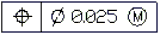
Note: You cannot associate Tolerances with drawing entities.
The Properties palette lets you change several display properties of Tolerances, such as:
- Style
- Color of the text and the frame
- Scale
If you select a Tolerance and the ribbon is active, the Tolerance contextual tab appears. The contextual tab groups options and tools for changing Tolerance properties.
The following tables describe the Tolerance and material condition symbols you can select in the Geometric Tolerance dialog box.
Geometric characteristic symbols
| Symbol | Characteristic | Type |
|---|---|---|
 |
Position | Location |
 |
Concentricity or coaxiality | Location |
 |
Symmetry | Location |
 |
Parallelism | Orientation |
 |
Perpendicularity | Orientation |
 |
Angularity | Orientation |
 |
Cylindricity | Form |
 |
Flatness | Form |
 |
Circularity or roundness | Form |
 |
Straightness | Form |
 |
Profile of a surface | Profile |
 |
Profile of a line | Profile |
 |
Circular runout | Runout |
 |
Total runout | Runout |
Material condition symbols
| Symbol | Definition | Type |
|---|---|---|
 |
At maximum material condition, a feature contains the maximum amount of material stated in the limits. | MMC |
 |
At least material condition, a feature contains the minimum amount of material stated in the limits. | LMC |
 |
Regardless of feature size, indicates that the feature can be any size within the stated limits. | RFS |
To create a Tolerance:
- Click Dimension > Tolerance (or type Tolerance).
- In the dialog box, from corresponding lists select symbols for geometric characteristics and material condition (M.C.) specifications. Select Diameter to turn on diameter symbols.
- Complete the specifications by typing tolerance values in the corresponding text boxes.
- Enter datum values as necessary and select appropriate material condition symbols.
- Enter a Datum identifier.
- Enter a Height for the Tolerance.
- Add the Projected tolerance zone symbol if necessary.
- Click OK.
- In the graphics area, specify the position of the Tolerance.
The Tolerance displays in the graphics area.
Access
Command: Tolerance
Menu: Dimension > Tolerance
Ribbon: Annotate > Dimensions > (Flyout) Tolerance
Editing Geometric Tolerances
Use the EditTolerance command to modify Tolerances.
To edit Tolerances:
- Click Modify > Entity > Tolerance (or type EditTolerance).
- In the graphics area, select the Tolerance to edit.
- In the Geometric Tolerance dialog box, modify the settings.
For detailled information about the dialog box, see Creating Geometric Tolerances.
- Click OK.
The modified Tolerance appears in the graphics area.
Access
Command: EditTolerance
Menu: Modify > Entity > Tolerance
Ribbon: Annotate > Dimensions > (Flyout) Tolerance Edit
Modifying Existing Dimensions
You can modify the appearance of existing Dimensions.
This topic discusses:
Section Contents
- Modifying Dimensions
- Modifying Dimension Orientations
- Adjusting the Space between Dimensions
- Splitting Dimension and Extension Lines at Intersecting Entities
- Flipping Dimension Arrows
- Modifying Dimension Text
- Overriding DimensionStyle Variables
- Rebuilding Dimensions
- Relating Dimensions
Modifying Dimensions
Use the EditDimension command to change the position, angle, and value of Dimension text. You can also change the orientation of the extension lines of Dimensions.
To modify Dimensions:
- Type EditDimension at the command prompt.
- Specify an option:
- Angle. Rotates the Dimension text of existing Dimensions. Specify the rotation angle. To revert rotated Dimension text to its default orientation, enter an angle of 0°. The option works the same as the Angle option of the EditDimensionText command except that you can specify multiple Dimensions with the EditDimension command.
- Home. Undoes the move or rotation of Dimension text and returns it to its original position (default).
- Move. Relocates the dimension line and the text of existing Dimensions in one operation.
- New. Modifies the Dimension text value. Enter a text value or <> to represent the generated measurement. You can revert the Dimension to its generated measurement or add a prefix or suffix to the generated measurement. For example N-<> generates the value N-24 if the Dimension measurement generates 24.
- Oblique. Modifies the orientation of existing linear Dimensions. Specify a new angle for the extension lines.
- Select the Dimension to update.
- Press Enter.
The specified Dimensions are updated.
Access
Command: EditDimension
Modifying Dimension Orientations
The ObliqueDimension command lets you modify the orientation of existing linear dimensions.
To modify dimension orientations:
- Type ObliqueDimension at the command prompt.
- In the graphics area, specify an obliquing angle for the extension lines.
- Specify the dimensions to modify.
- Press Enter.
Access
Command: ObliqueDimension
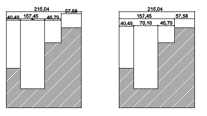
Adjusting the Space Between Dimensions
Use the SpaceDimension command to adjust the space between parallel linear or concentric angular dimensions that overlap or are not equally spaced. You can space parallel linear and angular dimensions automatically or at a specified distance.
The command applies equal spacing between specified dimensions.
You can line up a series of linear or angular dimensions line by using a spacing value of 0.
To adjust the space between Dimensions:
- Do one of the following:
- On the ribbon, click Annotate > Dimensions > Adjust Space.
- On the menu, click Dimension > Adjust Space.
- Type SpaceDimension.
- In the graphics area, specify the dimension to use as base dimension.
- Specify the dimensions to space and press Enter.
- Do one of the following:
- Specify the Auto option and press Enter.
Specified dimensions are equally spaced based on the text height specified in the dimension style of the selected base dimension. The distance is twice the height of the dimension text.
- Specify a spacing value and press Enter.
Specified dimensions are equally spaced at the specified distance.
- Specify the Auto option and press Enter.
Example:
Access
Command: SpaceDimension
Ribbon: Annotate > Dimensions > Adjust Space
Menu: Dimension > Adjust Space
Splitting Dimension and Extension Lines at Intersecting Entities
Use the SplitDimension command to split dimension and extension lines of Dimension entities where they intersect other entities. You can also join split dimension and extension lines.
You can either create splits in the dimension and extension line automatically at all intersections with other entities, or you can specify the split locations individually by selecting crossing entities one by one.
You can create dimension splits at Lines, Polylines, Arcs, Circles, Ellipses, Splines, Leaders, Notes, SimpleNotes, and other Dimensions. Splits are also created at entities of these types when they are part of Blocks or References. You can select the same entities when you rejoin split dimensions.
The default gap size is stored in DimensionStyles.
To split dimension and extension lines at intersecting entities:
- Do one of the following:
- On the ribbon, click Annotate > Dimensions > Split Dimensions.
- On the menu, click Dimension > Split Dimensions.
- Type SplitDimension.
- Do one of the following:
- In the graphics area, select a dimension entity.
- Specify the Multiple option, then select dimension entities in the graphics area, and press Enter to complete the selection.
- Optionally, specify any of the following options:
Option Description Default gap Splits dimensions using the default gap. Specify gap Lets you apply a split gap in individual cases by specifying a starting point and an endpoint.
This option is not available when you split multiple dimension and extension lines.Join Joins split dimension and extension lines. Exit Exits options setting. - Press Enter to automatically split dimension and extension lines at all locations where they cross other entities.
– or –
Specify crossing entities one by one to determine individually split locations. Press Enter to conclude the command.
To join split dimension and extension lines:
- Do one of the following:
- On the ribbon, click Annotate > Dimensions > Split Dimensions.
- On the menu, click Dimension > Split Dimensions.
- Type SplitDimension.
- Do one of the following:
- In the graphics area, select a dimension entity.
- Specify the Multiple option, then select dimension entities in the graphics area, and press Enter to complete the selection.
- Specify the Join option.
- Press Enter to automatically join dimension and extension lines at all locations where they were split at intersecting entities.
– or –
Specify crossing entities one by one to rejoin dimension and extention lines at specific split locations. Press Enter to conclude the command.
To set the default gap for dimension splits:
- Do one of the following:
- On the ribbon, click Annotate > Dimensions > Dimension Style.
- On the menu, click Format > Dimension Style.
- Type DimensionStyle.
In the Options dialog box, the Drafting Styles page opens and Dimension expands.
- Expand Line > Dimension split.
- In Split gap, set the width of the default gap when you use the SplitDimension command to split dimension and extension lines which cross other entities.
The specified value is stored in the active DimensionStyle.
Access
Command: SplitDimension
Ribbon: Annotate > Dimensions > Split Dimensions
Menu: Dimension > Split Dimensions
Parent Topic
Flipping Dimension Arrows
Use the FlipArrows command to change the position of dimension arrowheads.
You can apply the tool to any Dimensions that use arrows or ticks.
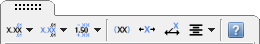
When you select Dimensions, flip arrow grips (![]() ) display near dimension arrows or ticks. Clicking such a grip flips the related arrowhead.
) display near dimension arrows or ticks. Clicking such a grip flips the related arrowhead.
To flip dimension arrows:
- Type FlipArrows in the command window.
- In the graphics area, select Dimensions.
The dimension arrows or ticks flip around the extension line or entity edge.
To flip dimension arrows with flip arrow grips:
- In the graphics area, select Dimensions.
- Click the flip arrow grip (
 ) on a dimension line with the arrowhead you want to flip.
Use the DimensionStyle command to set the style and size of dimension arrows.
Access
Command: FlipArrows
Modifying Dimension Text
You can modify the text, position, and appearance of existing Dimensions.
This topic discusses:
- Editing Dimension Text
- Resetting Dimension Text to Its Original Position
- Moving Dimension Text
- Rotating Dimension Text
- Modifying Dimension Text Values
- Modifying Dimension Text Using the Dimension Palette
Editing Dimension Text
Use the EditDimensionText command to move or rotate Dimension text for a single Dimension.
Use the EditDimension command to edit multiple Dimensions.
To edit Dimension text:
- Click Dimension > Align Text (or type EditDimensionText).
- Specify a Dimension.
- Specify a new position for the dimension text and dimension line.
– or –
Select an alignment option:
- Angle. Rotates the Dimension text about its center by the angle you specify.
- Center. Moves the text to a center-justified position within the Dimension.
- Home. Undoes the move of Dimension text and returns it to its original position.
- Left. Moves the text to a left-justified position within the Dimension.
- Right. Moves the text to a right-justified position within the Dimension.
The Dimension text moves as specified.
Use the EditDimension command to change the position, angle, and value of Dimension text. You can also change the orientation of the extension lines of Dimensions.
Access
Command: EditDimensionText
Menu: Dimension > Align Text
Ribbon: Annotate > Dimensions > Dimension Text Edit
Resetting Dimension Text to its Original Position
Use the ResetDimensionText command to undo moving Dimension text, returning it to its original position.
To reset Dimension text to its original position:
- Type ResetDimensionText at the command prompt.
- In the graphics area, select the Dimensions to realign.
- Press Enter.
The Dimensions revert to their original positions.
Access
Command: ResetDimensionText
Menu: Dimension > Align Text > Reset
Ribbon: Annotate > Dimensions > (Flyout) Align Text, Reset
Moving Dimension Text
Use the MoveDimensionText command to move Dimension text.
To move Dimension text:
- Type MoveDimensionText at the command prompt.
- In the graphics area, select a Dimension.
- Specify the new text position.
The Dimension text moves to the new location. The dimension line is aligned to the new position of the Dimension text.
Access
Command: MoveDimensionText
Rotating Dimension Text
Use the RotateDimensionText command to rotate Dimension text of specified Dimensions.
To rotate Dimension text:
- Type RotateDimensionText at the command prompt.
- Specify the angle to rotate the Dimension text.
- In the graphics area, select Dimensions, and press Enter.
The text of specified Dimensions rotates about the specified angle.
Access
Command: RotateDimensionText
Modifying Dimension Text Using the Dimension Palette
The Dimension palette appears when you insert or select a Dimension so you can change the properties and formatting of Dimension text.
You can change the tolerance, precision, and formatting in the palette without going to the Properties palette.
The palette is beneficial for reusing format settings for other Dimensions (for example, reference dimensions, or tolerances).
If you select more than one Dimension, the properties and formatting that you specify in the palette apply to all of the Dimensions.
The palette applies to linear, angular, radial, diameter, arc length, and ordinate Dimensions.
To display the Dimension palette:
- In the graphics area, insert or select a Dimension.
The Dimension palette tool
 appears to the upper right of the pointer.
 - Move the pointer over the tool to display the Dimension palette.
- Click anywhere in the palette to pin it.
The palette disappears if you move the pointer beyond the graphics area or clear the Dimension selection by another means.
Note: The Dimension palette is a context toolbar that you can turn off (See Dimension Palette Options).
Dimension Palette Overview
The Dimension palette has three areas:
- The buttons at the top let you change the properties and formatting of Dimension text and Tolerances.
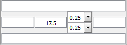
- The text boxes in the middle of the Dimension palette let you add text to the left, right, top, and bottom of the Dimension text. The Dimension text is located in the center of this area, and you can override it.
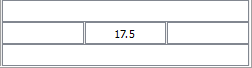
Additional text boxes are inserted behind the Dimension text box, if you apply a tolerance type (Symmetrical, Deviation, or Limits).
If you specify more than one Dimension, the Dimension text and Tolerances boxes may display "<varies>".
- The buttons at the bottom let you manage favorites for the appearance and formatting of Dimension text and Tolerances for subsequent use.
Dimension Text and Tolerance Properties and Formatting
| Option | Button | Description |
|---|---|---|
| Tolerance Display |  |
Specifies a tolerance format (Symmetrical, Deviation, Limits, Basic, or None). See Tolerance Formats. Selections available depend on the type of Dimension. |
| Unit Precision |  |
Sets the precision of the Dimension value from 0 to 8 decimal places. |
| Tolerance Precision |  |
Sets the number of decimal places for Tolerances (only available if Tolerance Display is set to Symmetrical or Deviation). |
| Add Parentheses |  |
Puts parentheses around Dimension text. Reference dimensions are shown in parentheses. |
| Center Dimension Text |  |
Centers the Dimension text between the extension lines. This option is similar to the EditDimension command with the Home option, which undoes the move of Dimension text and returns it to its original position. |
| Offset Dimension Text |  |
Determines the behavior of Dimension text movement: if cleared, the Dimension line location follows Dimension text movement; if selected, a leader connects the moved Dimension to the Dimension line which remains in its position. |
| Text Justification |  |
Establishes horizontal and vertical justification of the Dimension text. |
Tolerance Formats
Tolerance formats include:
- Symmetrical. Appends a plus/minus tolerance value to the Dimension measurement which indicates the positive and negative deviation in a single value.
- Deviation. Appends separate plus and minus values of deviation to the Dimension measurement.
- Limits. Displays a maximum and a minimum value, one on top of the other.
- Basic. Displays the additional Dimension measurement and deviation in a single value with a box around it.
- None. Does not generate a tolerance value.
Dimension Text Favorites Management
For repeated formatting of Dimension text, use Dimension text favorites.
You can save favorites in the drawing or in files of type *.dimfvt.
| Option | Button | Description |
|---|---|---|
| Apply Default |  |
Returns the selected Dimension(s) to their original state. The DimensionStyle associated with the Dimension entity applies to the entity in its entirety. |
| Save Favorite |  |
Adds or updates a favorite that is stored in the drawing. In the dialog box, specify a name or select an existing one. |
| Delete Favorite |  |
Deletes a favorite that is stored in the drawing. In the dialog box, specify the name of the favorite to delete. |
| Export Favorite |  |
Saves a favorite to a file of type *.dimfvt. Note that you must apply a named favorite in the drawing before you can save it to file. |
| Import Favorite |  |
Loads a favorite from a file of type *.dimfvt. If a favorite with the same name exists in the drawing, the favorite in the drawing and all associated Dimensions are updated by the settings of the favorite file. |
| Favorites List |  |
Shows a list of recently applied Dimension text and Tolerance settings and of recently saved favorites. For each item, a tooltip displays the Dimension value parameters. |
| Help |  |
Displays this help topic. |
Dimension Palette Options
You can turn on and off the use of the Dimension palette and set the path for Dimension text favorite files.
To set Dimension palette options:
- Type DraftingOptions at the command prompt.
In the Options dialog box, the User Preferences page opens and Drafting Options expands.
- Expand Dimension Palette.
- Click Enable Dimension palette to turn on or off the Dimension palette.
- In Favorites library path, set the path for Dimension text favorites files (*.dimfvt files). Click Browse to browse for the Dimension text favorites file folder.
- Click OK.
Modifying Dimension Text Values
Use the ReplaceDimensionText command to modify Dimension text values.
To modify Dimension text:
- Type ReplaceDimensionText at the command prompt.
- Type the new Dimension text value.
Type a text value or <> to represent the generated measurement. You can revert the Dimension to its generated measurement or add a prefix or suffix to the generated measurement. For example N-<> generates the value N-24 if the Dimension measurement generates 24.
- In the graphics area, select Dimensions and press Enter.
The text of the selected Dimensions updates.
Access
Command: ReplaceDimensionText
Overriding DimensionStyle Variables
Use the OverrideDimensionStyle command to change the setting of a DimensionStyle variable and apply the setting to Dimensions without modifying the active DimensionStyle.
To override DimensionStyle variables:
- Click Dimension > Override (or type OverrideDimensionStyle).
- Type the name of a DimensionStyle variable to override.
- Enter the new value.
- Continue entering DimensionStyle variables and values, and press Enter when done.
- In the graphics area, specify the Dimensions whose settings are to be overridden.
- Press Enter.
The specified Dimensions are updated.
To undo DimensionStyle overrides:
- Click Dimension > Override (or type OverrideDimensionStyle).
- Specify the Clear overrides option to undo any DimensionStyle variable overrides you have set up.
- In the graphics area, specify the Dimensions whose settings are to be overridden.
- Press Enter.
Access
Command: OverrideDimensionStyle
Menu: Dimension > Override
Ribbon: Annotate > Dimensions > (Flyout) Override
Rebuilding Dimensions
Use the RebuildDimension command to apply the active DimensionStyle to specified Dimensions.
Note that the active DimensionStyle permanently overrides the DimensionStyle previously applied to the specified Dimensions.
To rebuild Dimensions:
- Click Dimension > Rebuild (or type RebuildDimension).
- In the graphics area, select Dimensions and press Enter.
Specified Dimensions using other DimensionStyles appear in the active DimensionStyle.
Access
Command: RebuildDimension
Menu: Dimension > Rebuild
Ribbon: Annotate > Dimensions > (Flyout) Rebuild
Relating Dimensions
Use RelateDimension to reestablish the relation of Dimensions to entities. When you create a new drawing and modify a dimensioned entity, the related Dimension updates its position and text reflecting the entity’s changes. If you open existing drawings, sometimes the Dimensions are not related with entities.
To reestablish the relation of Dimensions to entities:
- Click Dimension > Relate Dimension (or type RelateDimension).
- In the graphics area, select Dimensions and press Enter.
Drawing entities that are not Dimensions are filtered out.
The first specified Dimension is highlighted.
- Follow the prompts for the first specified Dimension (or press Enter to skip to the next Dimension).
- For linear and aligned Dimensions: Select the first and second extension line origins. You can also specify that entities reestablish their relation with the linear Dimensions.
- For radius and diameter Dimensions: Select an Arc or Circle to reestablish their relation to radius or diameter Dimensions.
- For 3-point angular Dimensions: Select the angle vertex, the first angle end point, and the second angle end point. You can also specify an Arc or Circle to associate with the angular Dimension.
- For 2-line angular Dimensions: Select a first and a second Line to relate these entities to an angular Dimension based on two Lines.
- For ordinate Dimensions: Select a new feature location to reestablish ordinate Dimensions to points.
- For leader Dimensions: Select a new relation point for the Leader.
The Dimension text updates automatically.
- If you selected more than one Dimension, repeat step 3 as needed.
Note: You might need to edit the location of the dimension lines because the newly related Dimension might not be positioned optimally after the update.
Access
Command: RelateDimension
Menu: Dimension > Relate Dimension
Ribbon: Annotate > Dimensions > (Flyout) Reassociate Dimension