Introduction
You can modify entities in many ways.
Use these basic editing methods:
- Selecting entities for modification
- Modifying entities using EntityGrips
- Correcting mistakes
- Using the clipboard
- Changing entity properties
You can also use these specific methods to modify entities:
- Copying, mirroring, moving, rotating, and scaling entities
- Copy, move, rotate, and scale in one operation
- Offsetting entities
- Stretching and lengthening entities
- Extending and trimming, chamfering, and filleting entities
- Splitting and welding entities
- Discarding duplicate entities
In addition to these editing methods, you can use commands to modify specific entities:
- Exploding complex entities
- Modifying 2D and 3D PolyLines
- Editing Hatches and Fills
- Editing Annotations
- Editing BlockAttributes
Selecting Entities for Modification
You must specify one or more entities for most editing commands. Selecting entities effectively helps you modify them efficiently. For example, you can specify a group of entities and apply a modification command to the entire group, called a selection set.
You can also create entity selection filters you use to create selections based on criteria like entity types and entity properties.
You cannot achieve everything with modifying commands, but you can do fundamental operations like stretching, moving, mirroring, rotating, and scaling drawing entities.
This section discusses:
- Selecting Entities
- Applying Entity Selection Methods
- Previewing and Highlighting Entity Selections
- Cycling Through Overlapping Entities During Selection
- Preselecting Entities
- Preselecting All Entities
- Selecting Entities of the Same Type and Shared Properties
- Creating Entity Selections Based on Filtering Criteria
- Creating and Applying Filters for Entity Selection
Selecting Entities
For many commands, especially the commands for modifying and detailing entities, you need to select drawing entities.
To select entities, you do not enter a separate command. Instead, you use selection tools.
Selected entities are highlighted by default. You can customize entity selection previewing and highlighting (see Previewing and Highlighting of Entity Selections).
To select entities:
- Enter a command that requires you to select entities.
The following prompt appears:
Specify entities»
- To view all options for entity selection, specify the ? option:
Specify entities» ?
Specify a point or Window, Last, Crossing, Box, All, Fence, WPolygon, CPolygon, EGroup, Add, Remove, Multiple, Previous, Undo, Auto, Single
Specify entities»For a description of each of the entity selection options, see Applying Entity Selection Methods.
- In the graphics area, select entities.
Selections are highlighted by default.
All entities you select are added to a selection set.
- Continue adding entities to the selection set or removing entities from it.
To remove previously selected entities from the selection set, press Shift and select entities.
- After selecting all desired entities, finish the selection by pressing Enter.
The current command resumes.
Applying Entity Selection Methods
When prompted to specify entities, enter one of the options (or the shortcut in parentheses) from the following table.
| Window (w) | Specifies all entities that lie completely within a rectangle defined by two opposite points. |
|---|---|
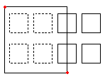 |
A rectangular selection Window is defined by two opposite corner points. Position the pointer on the first corner of the selection window and click that point. Click on the second corner point to specify all entities located entirely within the window. |
| Crossing (c) | Specifies entities within a rectangle defined by two opposite points. The entities can extend beyond the rectangle. |
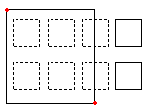 |
When specifying entities using the Crossing method, entities whose outlines intersect or lie within the window are selected. Position the pointer so that its window includes or intersects the desired drawing entities. |
| WPolygon (wp) | Specifies entities that lie completely inside a polygon defined by specified points. |
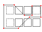 |
Like the Window mode, the Window Polygon mode specifies all drawing entities whose contours lie entirely inside the selection window. Unlike the Window mode, the Window Polygon mode lets you sketch an irregular window with unlimited corner points. To use WPolygon, define the corner points for the selection window. Polygon lines can intersect themselves and form loops. Press Enter to complete the selection window. All entities that lie totally inside of the window are selected. |
| CPolygon (cp) | Specifies entities within a polygon defined by specified points. The entities can extend beyond the polygon. |
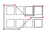 |
The Crossing Polygon selection mode also creates an irregularly formed window with unlimited corner points. All entities positioned inside or intersected by the selection polygon are specified. Define corner points for the selection window. The preview mode shows the emerging polygon. Polygon lines can intersect themselves and form loops. Press Enter to complete the selection window. All entities within and intersecting the crossing polygon are specified for modification. |
| Fence (f) | Specifies all entities that pass through a fence you determine. The Fence method is similar to CPolygon except that the fence is not closed. |
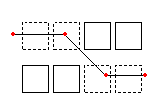 |
The Fence mode is an effective variant of a crossing selection mode. The entities to specify are not enclosed or crossed by a window, but instead are “cut through” by a line, or “fence”. Define the fence with unlimited points. The fence can intersect itself. Press Enter to complete the fence. All entities that intersect the line are added to the selection set. |
| Previous (p) | Specifies the most recent entity selection set again. |
|
The Previous option restores the previous selection set. Note: As with the Last and All methods, entities on a frozen Layer are not selected, and entities on a locked Layer are selected but cannot be handled. |
|
| Last (l) | Specifies the most recently created visible entity. |
|
The Last option adds the last drawn entity to the selection set. Note: If the last drawn entity is located on a frozen Layer, no entity is selected. |
|
| Group (eg) | Specifies the entities of a specified EntityGroup. |
|
The EGroup option selects the entities of an EntityGroup specified by the group’s name. Create EntityGroups using the EntityGroup command. |
|
| Add (a) / Remove (r) | Toggles between the default Add and Remove mode. |
|
The Add option is the default mode, letting you specify entities and add them to the selection set at any time. The Remove option instead removes previously selected entities from the selection set. Remove mode changes the entity selection prompt to Remove Entities. Entities already selected are removed from the selection set if they are selected again. |
|
| Undo (u) | Deselects the most recently selected entities. |
The Undo option reverses the most recent selection. |
|
| All (all) | Specifies all entities on all Layers. |
The All option selects all entities in the drawing except those located on frozen Layers. |
|
| Single (si) / Multiple (m) | Toggles between the Single and Multiple selection method. |
|
With Single mode, you specify one entity, then entity selection completes. With Multiple mode, you select entities by specifying multiple points without highlighting the entities. Multiple mode also selects two intersecting entities even if the intersection point is chosen twice. |
|
| Auto (au) | Toggles to the Automatic mode where pointing to an entity selects the entity. Pointing to an empty location initiates an entity selection box. |
Auto and All are default modes for entity selection. |
|
| Box (box) | Specifies entities with a pointer method that is a combination of Windows and Crossing. If the opposite points of the selection rectangle are specified from right to left, Box is equivalent to Crossing. Otherwise, Box is equivalent to Window. |
 |
Drawing the window from left to right specifies entities within the selection window. |
 |
Drawing the window from right to left specifies entities within and intersecting the selection window. |
Click-Drag Selection / Lasso Selection
The traditional methods of entity selection use clicks to specify entities for modification (Click and click method):
- Click on any part of an individual entity you want to select.
- With two consecutive clicks in the graphics area, specify a rectangle:
- Window selection: Click in the graphics area, move the cursor to the right, then click again. Any entities that fall completely into the area are selected.
- Crossing selection: Click in the graphics area, move the cursor to the left, then click again. Any entities that lie completely or partially within the selection area will be selected.
Additional methods include entity selection by clicking and dragging the cursor, then release the pick button (Click and drag method):
- Click and Drag Selection. Lets you select entities by specifying a rectangular area (window selection or crossing selection).
- Lasso Selection. Lets you select entities by sketching a lasso around entities.
To adjust the selection methods, see Setting Selection Methods.
Click-Drag Selection
Use the click and drag selection method to specify entities within a rectangular selection area by dragging the cursor.
To use click and drag selection:
- In the graphics area, click and drag the cursor.
The preview mode shows a rectangular selection area:
- Window selection: When you drag the cursor from left to right, only entities that fall completely into the selection area are selected.
- Crossing selection: When you drag the cursor from right to left, any entities that lie completely or partially within the selection area will be selected.
- Release the pick button to complete the selection.
Lasso Selection
Use the lasso selection method to specify entities within a lasso contour by dragging the cursor.
The lasso selection method creates an irregularly formed contour. All entities positioned inside and probably intersected by the lasso contour are selected.
To use lasso selection:
- In the graphics area, click and drag the cursor.
The preview mode shows the emerging lasso contour. The contour can intersect itself and form loops.
Press the spacebar by holding down the pick buttion to cycle between three entitiy selection modes:
- Window. Only entities that fall completely into the selection area are selected
- Crossing. Any entities that lie completely or partially within the selection area will be selected
- Fence. All entities that cross the fence are selected.
- Release the pick button to complete the selection.
Setting Selection Methods
You can control the entity selection method by clicking and dragging:
- Consecutive clicks: In the graphics area, specify a point, then specify the opposite corner for the selection window.
- Click and drag: In the graphics area, specify a point and hold down the left mouse button, then drag and release the mouse button at the other corner of the selection window. You can use Lasso selection as an alternative click and drag method.
To specify the method for selection windows:
- Do one of the following:
-
Click Tools > Options (or type Options).
Click Tools > Options (or type Options).
Click Application menu > Preferences (or type Options).
In the Options dialog box, click User Preferences
 .
. - Type UserPreferences.
-
- Expand Mouse Options > Options.
- In Method for selection windows specify the method of using selection windows:
- Click and click. Specifies the selection window using two points (consecutive clicks).
- Click and drag. Specifies the selection window by click and drag.
- Automatic detection. Specifies the selection window using either of the methods above (default).
To specify the Click-Drag and Lasso selection options:
- Do one of the following:
-
Click Tools > Options (or type Options).
Click Tools > Options (or type Options).
Click Application menu > Preferences (or type Options).
In the Options dialog box, click User Preferences
 .
. - Type UserPreferences.
-
- Expand Drafting Options > Entity Selection > Selection Settings and set:
Previewing and Highlighting Entity Selections
Entities are highlighted when you move the cursor over them (preview highlighting) or when you select them (selection highlighting).
Highlighting helps you recognize whether the entities are elementary ones (such as Lines or Arcs) or compound ones (such as Blocks, Dimensions, Polylines, RichLines, or Tables) before and during entity selection.
You can customize preview highlighting and selection highlighting by:
- Controlling preview highlighting independently when a command is active or inactive
- Excluding certain command types from highlighting: entities on locked layers, References, Tables, Notes, Hatches, and entities which are part of EntityGroups
Use the Options command to customize the settings.
To set the color for preview highlighting and selection highlighting:
- In the Options dialog box, click System Options.
- Expand Display > Element Colors.
- To change the highlighting behavior back to legacy dashed-style entity highlighting, select Use dashed entity selection.
In this case, you cannot access the Dynamic Highlight and Selected Entity items in the list of elements and the following steps are obsolete.
If you deactivated Use dashed entity selection:
- Specify a value for the Selection highlight effect opacity between 0.10 and 1.00.
- Specify a value for the Selection highlight effect thickness between 2.00 and 8.00.
- In the list, click Dynamic Highlight.
- In Color, specify the color for preview highlighting.
- In the list, click Selected Entity.
- In Color, specify the color for selection highlighting.
- Click Apply.
To set preview highlighting options:
- In the Options dialog box, click User Preferences.
- Expand Drafting Options > Entity Selection > Pre-selected Highlighting and set:
- When prompted to specify entities: Highlights entities when you are prompted to specify entities during command execution and you move the cursor over the entities.
- Between commands: Highlights entities when you move the cursor over them if no command is active.
- Click Apply.
To exclude entities from highlighting:
- In the Options dialog box, click User Preferences.
- Expand Drafting Options > Entity Selection > Preview Filter.
- In Exclude, select entity types to exclude from highlighting:
- Entities on locked layers: Excludes entities on locked layers.
- Notes: Excludes Notes.
- References: Excludes entities in externally referenced drawings (References).
- Hatches: Excludes Hatches and gradient color fills.
- Tables: Excludes Tables.
- Groups: Excludes entities in EntityGroups.
- Click Apply.
Cycling Through Overlapping Entities During Selection
Cycling selection lets you selectively specify entities that are close to or on top of other entities.
You can preselect entities with this method or use them when you are prompted to specify entities in the graphics area.
To identify entities that are close together but do not overlap exactly, it can be useful to zoom near to the entities.
When you hover the pointer over entities that are close to each other or overlap, the stack icon ![]() appears. Pressing Ctrl + W when the cursor is on overlapping entities hides the icon.
appears. Pressing Ctrl + W when the cursor is on overlapping entities hides the icon.
To cycle through overlapping entities during selection using a list of detected entities:
The following command sequence assumes the display of a list of detected drawing entities is turned on. See Cycling Selection Settings.
- Make sure the Cycling Selection feature is turned on.
Right-click Cycling Selection on the status bar and select On to activate the feature.
- Hover the pointer over entities that are close to each other or overlap.
The stack icon
 appears near the entities if more than one entity passes through the selection box.
 - Click to the location where the icon displays.
A list of entities that overlap appears. The last created entity is the first in the list. In front of the entity names, the entity color is displayed, which helps to distinguish the entities.
When you move the cursor over the list, the entity highlighted in the list will also be highlighted in the drawing.
- In the list, click the highlighted entity to select it.
- Apply a modification command on the selected entity or use the entity’s grips to modify it.
- Repeat steps 2 to 5 as needed to specify multiple entities that are close to each other or overlap.
To cycle through overlapping entities during selection without using the list of detected entities:
The following command sequence assumes the display of a list of detected drawing entities is turned off. See Cycling Selection Settings.
- Make sure the Cycling Selection feature is turned on.
Right-click Cycling Selection on the status bar and select On to activate the feature.
- Hover the pointer over entities that are close to each other or overlap.
The stack icon
 appears near the entities if more than one entity passes through the selection box.
Note: You can cycle through overlapping entities by holding down the Shift key, and pressing the Spacebar to highlight detected entities one after the other.
- Click the highlighted entity.
- Apply a modification command on the selected entity or use the entity’s grips to modify it.
- Repeat steps 2 to 4 as needed to specify multiple entities that are close to each other or overlap.
To turn cycling selection on or off:
- Right-click Cycling Selection on the status bar and select On or Off.
- Press Ctrl + W.
Cycling Selection Settings
To set cycling selection display options:
- Right-click Cycling Selection on the status bar and select Settings.
- Under Drafting Options > Entity Selection > Selection Settings, select or clear Enable cycling selection.
- Select or clear Show list of entities.
Note: To set the Selection Box size, use the Options command. Type DraftingOptions, and expand Entity Selection > Selection Settings. In SelectionBox size, change the size.
Preselecting Entities
Use the Select command to choose drawing entities for subsequent modification commands.
To create a selection set:
- Do one of the following:
- Type Select at the command prompt.
- Click Select Entities
 on the Properties palette toolbar.
- Click on entities to add to the selection set or use entity selection modes to fine tune selections, then press Enter.
- Apply a modification command.
- At the Specify entities prompt, type Previous to apply the most recent selection set.
Access
Command: Select
Preselecting All Entities
Use the SelectAll command to select all drawing entities for subsequent modification commands.
To preselect all entities:
- Click Edit > Select All (or type SelectAll).
All entities except those located on frozen or locked Layers are selected.
If EntityGrips are turned on, EntityGrip Nodes appear on the selected entities.
- Apply a modification command.
 Note: You cannot use SelectAll as the selection method in a running command. Instead, use the All option when prompted to specify entities.
Access
Command: SelectAll
Menu: Edit > SelectAll
Selecting Entities of the Same Type and Shared Properties
Use the SelectMatching command to select drawing entities of the same type and with shared properties. This helps you to use subsequent commands on the group of entities.
You select entities that represent the types to set as selection criteria (Line, Arc, Circle, PolyLine, Block, etc.).
The properties you can apply as selection criteria are: Entity style, Layer, LineColor, LineStyle, LineScale, LineWeight, PrintStyle, and Name. Entity styles include TextStyles, TableStyles, and DimensionStyles. Names includes Block names and the names of referenced objects (referenced drawings and images).
To select entities of the same type and shared properties:
- Type SelectMatching at the command prompt.
- In the graphics area, specify one or more entities of the type and properties you want to match.
- Optionally, specify the Settings option:
- In the dialog box, select or clear properties to define selection creteria.
- Click OK.
- Press Enter.
The entities which match type and properties of the specified entities are highlighted.
- Apply a modification command.
- At the Specify entities prompt, type Previous to apply the most recent selection set.
Access
Command: SelectMatching
Creating Entity Selections Based on Filtering Criteria
Use the SmartSelect command to create selection sets based on filtering criteria.
To create selection sets based on filtering criteria:
- Do one of the following:
- Type SmartSelect at the command prompt.
- Click Smart Select
 on the Properties palette toolbar.
- In the dialog box, in Apply to, select whether the criteria applies to the entire drawing or the current selection set, if one exists.
To specify entities in the graphics area, click
 , then press Enter.
 - In Entity, select whether to apply the criteria to a specific entity type or select Multiple to apply the criteria to all types.
- In Property, select a property for which you want to define a filter expression.
- In Operator, select the operator for the filter expression.
- For Value, type a filter value. Available values are extracted from the drawing. For example, if you set Property to Layer, Value displays a list with all layer names.
- Set Selection results:
- Add to Selection Set: Creates a selection set of entities that match the criteria.
- Remove from Selection Set: Creates a selection set of entities that do not match the criteria.
- Select Add to existing Selection Set to add the selection set to the existing selection set. When cleared, the selection set replaces the existing selection set.
- Click OK to apply the filter.
- Run a modification command.
- Specify the Previous option at the command prompt to apply the selection set you created.
Access
Command: SmartSelect
Creating and Applying Filters for Entity Selection
Use the SelectionFilter command to filter entities for selection.
You can
- Create complex selection filters, using relational and logical operators.
- Apply selection filters transparently during the execution of modification commands.
- Save and apply named filters.
After you select entities based on the filter, modify the entities using the modification commands or the Properties palette.
Note: The command does not create a selection set. It defines criteria to apply on a selection set.
To create and apply selection filters:
- Type SelectionFilter at the command prompt.
- In the dialog box, in Filter type, select an entity type, an entity type with property, or a property.
- If you selected an entity with property:
In the dialog box:
- Specify a relational operator (*, =, !=, >, >=, <, or <=).
- Specify a value.
- Click OK.
- Click Add
 to add the the item to the filter list.
 - In Operator, set a logical operator (AND, OR, NOT, or XOR) if needed.
Use logical operators to group filter expressions.
- If you selected a logical operator, click Add
 to add the operator to the filter list.
 - Use options as needed:
- Click Add Entity
 and click in the graphics area to add an entity to the selection filter.
The dialog box closes temporarily until you select a drawing entity to add to the filter list.
- Click Delete
 to selectively remove filter list items.
 - Click Clear List
 to clear the selection filter list.
- Click Add Entity
- Repeat steps 2 to 7 as needed.
- Click OK.
The selection filter is now active.
Note: At this point no selection set is created. Unlike the SmartSelect command, it defines criteria to apply on a selection set. It is important to continue with the next step.
- In the graphics area, specify the entities to which you want to apply the selection filter.
You can use any of the entity selection methods.
- Press Enter to conclude entity selection.
- Run a modification command.
The command uses the preselection (step 10). It does not prompt to specify entities.
To reapply selection filters with the next modification command:
- Run a modification command.
- Specify the Previous option at the next Specify entities prompt.
Using selection filters transparently
You can apply selection filters as transparent command by typing ‘SelectionFilter at the “Specify entities” prompt of modification commands.
To use selection filters transparently:
- Invoke a command to modify drawing entities (for example, Copy).
- At the “Specify entities” prompt, type ‘SelectionFilter.
- In the Selection Filter dialog box, define a new filter or select an existing named filters.
- Click OK.
- In the graphics area, specify the entities to which you want to apply the selection filter and press Enter.
- Follow the prompts of the modification command.
Working with named selection filters
You can save selection filters under a name and reapply the named filters.
Selection filters are stored in the user’s profile, not in the drawing and you can apply them on your computer.
 You can store several saved selection filters into a.flt file to use them on another computer or to exchange selection filters with your colleagues. See Exporting and Importing Named Selection Filters.
Note: Selection filters parameters that do not match property settings within the current drawing (such as Layer name specifications) are ignored when applying the filter.
To save named selection filters:
- In the Selection Filter dialog box, define a selection filter as described above.
- Type a name for the filter in the text box next to the Save button and click Save.
The selection filter name appears in the Named filter, select a saved filter.
To apply saved selection filters:
- Type SelectionFilter at the command prompt.
- In Named filter, select the name of the selection filter to apply.
- Click OK.
- Invoke a modification command.
- In the graphics area, specify the entities to which you want to apply the selection filter.
To delete named selection filters:
- In the Selection Filter dialog box, in Named filter, select a filter to delete and click Delete
 .
.
Exporting and Importing Named Selection Filters
You can use FLT files to exchange named selection filters with your colleagues.
Use export and import features from the Selection Filter dialog box to:
- Save specified named selection filters to a .flt file.
- Import specified named selection filters from a .flt file.
To export named selection filters:
- Type SelectionFilter at the command prompt.
- In the Selection Filter dialog box, click Export.
- Type the file name for the .flt file.
- Click Save.
- In the Selection Filter – Export dialog box, select the named filters to export.
Click Clear all to cancel the selections or Select all to select all named filters.
- Click OK.
To import selection filter files:
- Type SelectionFilter at the command prompt.
- In the Selection Filter dialog box, click Import.
- Select the .flt file and click Open.
The Selection Filter – Import dialog box displays the named filters available in the selected .flt file.
- In the Selection Filter – Import dialog box, select the named filters to import.
Click Clear all to cancel the selections or Select all to select all named filters.
- Click OK.
All selected named filters apear in the Named filter list, in the Selection Filter dialog box.
Note: Selection filters from the .flt file that have the same name as exiting filters on your computer are not imported.
Operators Overview
Relational Operators
| Operator | Description | Examples |
|---|---|---|
| * | Equal to any value | All Circles without any restriction |
| = | Equal | All Circles with radius=2.54 |
| != | Unequal | All Circles with radius other than 2.54 |
| > | Greater than | All Circles with radius greater than 2.54 |
| >= | Greater than or equal to | All Circles with radius greater than or equal to 2.54 |
| < | Lower than | All Circles with radius less than 2.54 |
| <= | Lower than or equal to | All Circles with radius less than or equal to 2.54 |
Logical Operators
| Operator | Description | Examples |
|---|---|---|
| AND | Filter items that meet all criteria (can enclose one or more criteria) | All Circles on Layer "Screws" |
| OR | Filter items that meet any of the criteria (can enclose one or more criteria) | All Circles and all entities on Layer "Screws" |
| NOT | Filter items that do not meet the criteria (must enclose only one criterion) | All entities on Layer "Screws" that are not Circles (if applied to the Circle entity type criterion) |
| XOR | Filter items that meet one or the other criteria, but not both (must enclose two criteria) | All Circles not on Layer "Screws" and all entities on Layer "Screws" that are not Circles |
Examples
The following examples show the filter list contents.
All Circles with a radius greater than 2.54 drawing units:
 AND
AND
 Circle
 Radius > 2.54
All Circles and all entities on Layer “Screws”:
 OR
OR
 Circle
 Layer “Screws”
Access
Command: SelectionFilter
Modifying Entities Using the Heads-Up Display Toolbar
You can use a Heads-up Display toolbar that appears when you select entities in the graphics area:

Using Heads-up Display, you can quickly zoom to the specified entities, change the entities Layer, LineStyle, and LineWeight, dimension entities, or create a Block from the entities.
You can turn the Heads-up Display on and off.
The toolbar is dragable. If you do not click an option, it disappears shortly thereafter. To redisplay it, specify an entity that you already selected. You can set the display duration of the toolbar.
To turn the Heads-up Display toolbar on and off:
- Click Tools > Options (or type Options).
- In the dialog box, expand User Preferences > Drafting Options > Heads-Up Display.
- Do one of the following:
- Click Enable heads-up toolbar to display the Heads-up Display toolbar automatically when you select entities.
- Clear Enable heads-up toolbar to prevent the display of the Heads-up Display toolbar.
- In Heads-up toolbar display time, set a time (in milliseconds) before the Heads-up toolbar disappears from display.
- Click OK.
To modify entities using the Heads-up Display toolbar:
- In the graphics area, specify one or more entities.
The Heads-up Display toolbar appears near the pointer.
- Select an option:
Option Button Description See also Zoom to Selection 
Zooms to the bounding box of the selected entities. Zoom to Selected Entities LineStyle 
Sets the LineStyle for the selected entities. To load LineStyles, use the LineStyle command. Loading and Setting LineStyles LineWeight 
Sets the LineWeight for the selected entities. Setting the Active LineWeight Layers Manager 
Displays the Layers Manager dialog box. You can create or modify Layers. Managing Layers Entity to Active Layer 
Changes the Layer of the selected entities to the active Layer. Changing Entities to the Active Layer Change Entity Layer 
Changes the Layer of the selected entities to match a destination Layer. Specify an entity on the destination Layer or specify the Layer Name option and select a Layer in the Choose New Layer dialog box. Matching Layers SmartDimension 
Creates a linear, radial, or diameter Dimension depending on the entity you selected. This option invokes the SmartDimension command. Using SmartDimensions Make Block 
Creates a Block from the selected entities. This option invokes the MakeBlock command. Defining Blocks
Using EntityGrips
Modifying with EntityGrips (EGrips) is a direct and interactive way to manipulate entities. In the graphics area, you select an entity, select one of its EntityGrip, then modify the entity.
You use EntityGrips to drag defining points of entities to new positions (stretching), or to move, rotate, scale, mirror, or copy entire entities.
This section discusses:
Modifying with EntityGrips
You can modify entities with EntityGrips when no command is active. You select entities before you specify editing options.
EntityGrips (EGrips) are selectable handles (displayed as small squares) at the endpoints, center, vertices, insertion points, and other geometric points of entities.
The location of EntityGrips depends on the entity. For example, a Circle displays an EntityGrip at the center and four EntityGrips on the circumference. For the EGrip nodes on particular entities, see Applying EntityGrip Nodes.
You use EntityGrips to drag defining points of entities to new positions (stretching), or to move, rotate, scale, mirror, or copy entire entities.
To stretch and move entities with EntityGrips:
- In the graphics area, select entities to modify.
The entities change to dotted outlines (showing that they are selected), and the selectable handles appear on the entities (blue by default, known as "cold grips").
- Click an EGrip.
The EGrip changes color (red by default, knowns as "hot grips"), and the EGrip options display in the command window.
- Stretch the entity by moving the activated EGrip to another location and click on the drawing.
For EGrip edit mode, you can set:
- Base point: Specifies a base point other than the highlighted base EGrip.
- Copy: Leaves the specified entity at its current location as you modify a copy.
- Undo: Cancels the previous EGrip editing action as long one or more EGrips are highlighted.
- Exit: Terminates EGrip editing. Highlighted modification EGrips disappear, but selection EGrips still display.
 Note: To clear EGrips from the specified entity or set of entities, press Esc.
To stretch, move, rotate, scale, and mirror entities with EntityGrips:
- In the graphics area, select entities to modify.
- Click an EGrip.
- Press the Spacebar repeatedly to cycle through the following commands:
-
**STRETCH**. Stretches the entity from the selected EGrip location to the destination point you specify.
Unlike other commands, stretching modifies only one entity.
- **MOVE**. Moves the entities from the EGrip location to the destination point you specify.
- **MIRROR**. Mirrors the entities about the axis defined by the EGrip and a second point you specify.
- **ROTATE**. Rotates the entities about the EGrip as an axis with the rotation angle you specify.
- **SCALE**. Scales the entities with the selected EGrip as a base point with the scale factor you specify.
After **SCALE**, the cycle sequence repeats.
-
**STRETCH**. Stretches the entity from the selected EGrip location to the destination point you specify.
- Specify the modification point, rotation angle, or scale factor according to the command you selected.
At this point you can also use the options Base point, Copy, Undo, and Exit (see above), before you complete the selected command.
To stretch multiple entities using EntityGrips:
- In the graphics area, select entities to modify.
The selectable handles appear on the entities as "cold grips."
-
Shift + click several EGrips to highlight them.
The specified EGrips change color and appear as "hot grips."
- Release Shift.
- Specify one EGrip as the base grip.
- Move the base grip to another location and click on the drawing.
To set EntityGrip preferences:
 Note: EntityGrips are not accessible on drawing entities on locked Layers.
Applying EntityGrip Nodes
EntityGrips (EGrips) are selectable handles displayed as small squares at the end points, centers, vertices, insertion points, and other geometric points of entities.
You can use EntityGrips to stretch, move, and copy drawing entities.
The following table lists entities that have EGrips, where they are located, and how the EGrips modify the entity.
EntityGrip Nodes and Editing Results
| Entity | Node | Result |
|---|---|---|
| Line | Start point, Endpoint | Modifies this point, stretches the Line |
| Mid point | Moves the Line | |
| PolyLine | Vertex | Moves this point |
| Ray | Start point | Modifies this point, moves the Ray |
| Through point | Modifies this point, rotates the Ray | |
| InfiniteLine | Point of origin | Modifies this point, moves the InfiniteLine |
| Through point | Modifies this point, rotates the InfiniteLine | |
| RichLine | Start point, Endpoint | Modifies this point, stretches the RichLine |
| Vertex | Moves this point | |
| Arc | Center point | Moves the Arc |
| Endpoints | Stretches the Arc | |
| Midpoint | Stretches the Arc | |
| Circle | Center point | Moves the Circle |
| Four circumference points | Modifies the radius | |
| Ellipse | Center point | Moves the Ellipse |
| Four circumference points | Modifies the primary or secondary radius | |
| Elliptical Arc | Center point | Moves the Ellipse |
| Endpoints | Stretches the point | |
| Four circumference points | Modifies the primary or secondary radius | |
| Spline | Vertex | Moves this point |
| Hatch | Insertion point | Moves this point |
| Insert (for Blocks) | Insertion point | Moves this point |
| BlockAttribute | Insertion point | Moves this point |
| BlockAttribute Definition | Base point | Moves this point |
| Point | Point | Moves this point |
| SimpleNote | Base point | Moves this point |
| Note | Base point | Moves this point |
| Dimension | Origin of extension line | Moves this point and the extension line |
| Endpoints of the dimension line | Moves the dimension line and text | |
| Dimension point text mid point | Moves the dimension line and text | |
| Leader | Insertion point | Insertion point: Moves the point |
| Tolerance | Insertion point | Moves the point |
| Table | Corner point | Resizes the Table |
| Table cell | Midpoints on horizontal border lines | Resizes the Table row |
| Midpoints on vertical border lines | Resizes the Table column | |
| 3D Face | Three or four vertices | Moves this point |
| 2D Solid | Three or four vertices | Moves this point |
| Viewport (on Sheets) | Four corner points | Resizes the Viewport |
Applying Multifunctional EntityGrips
Some EntityGrips are multifunctional. You can edit specific entities from shortcut menus or by cycling through options.
The following table lists entities that have multifunctional EGrips, where they are located on the entities, additional options available on the shortcut menu, and how the EGrip options modify the entity.
Multifunctional EntityGrips and Editing Results
| Entity | EGrip Location | Additional Option | Result |
|---|---|---|---|
| Line | Endpoints | Edit Length | Lengthens the Line. Type the new length or specify a point. |
| Arc | Center point | Edit Length | Lengthens the Arc. Type the new length or specify a point. |
| Circumference midpoint | Radius | Modifies the radius. Type the new radius or specify a through point. | |
| PolyLine | Vertex | Insert Vertex | Inserts a new vertex. Specify the location of the new vertex. |
| Delete Vertex | Deletes the highlighted vertex. | ||
| Midpoint between two vertices | Insert Vertex | Inserts a new vertex. Specify the location of the new vertex. | |
| Convert to Arc / Convert to Line | Changes a linear segment to a curved segment or a curved segment to a linear segment. | ||
| Dimension | Endpoints of the dimension line | Continue Dimension | Continues a linear, angular, or ordinate Dimension. Specify subsequent extension line origins. See Creating Continuous Dimensions. |
| Baseline Dimension | Creates a series of parallel linear Dimensions that share the same baseline. Specify subsequent extension line origins. See Creating Baseline Dimensions. | ||
| Flip Arrow | Changes the position of the dimension arrow at the dimension line endpoint. See Flipping Dimension Arrows. | ||
| Dimension text insertion point | Move with Dim Line | Moves the dimension text together with the dimension line. Specify the new position of the dimension text and dimension line. | |
| Move Text Only | Moves the dimension text and leaves the dimension line and extension lines unchanged. Specify the new position of the dimension text. | ||
| Move with Leader | Moves the dimension text and places a leader between dimension line and dimension text. Specify the new position of the dimension text. Applies to linear, angular, and ordinate Dimensions. | ||
| Above Dim Line | Places the dimension text above the dimension line. | ||
| Center Vertically | Centers the dimension text vertically between the extension lines. | ||
| Reset Text Position | Returns the dimension text to its original position. | ||
| Hatch | Insertion point | Stretch | Moves the hatch. Specify the new position of the hatch. |
| Origin Point | Modifies the hatch start point. Specify the new position of the hatch start point. | ||
| Hatch Angle | Modifies the hatch angle. Type the new angle or specify through point. | ||
| Hatch Scale | Modifies the hatch spacing. Type the new value or specify through point. | ||
| Vertex | Stretch | Moves the vertex. Specify the new position of the vertex. | |
| Insert Vertex | Inserts a new vertex. Specify the location of the new vertex. | ||
| Delete Vertex | Deletes the highlighted vertex. | ||
| Midpoint between two vertices | Stretch | Moves the vertex together with the segment. Specify the new position of the segment. | |
| Insert Vertex | Inserts a new vertex. Specify the location of the new vertex. | ||
| Convert to Arc / Convert to Line | Changes a linear segment to a curved segment or a curved segment to a linear segment. |
Setting EntityGrip Preferences
Use the EntityGrips command to enable or disable EntityGrips (EGrips), set the size of EGrips, and set the color for specific states of EGrips.
To set EntityGrip preferences:
- Do one of the following:
- On the menu, click Tools > Options.
- On the ribbon, click Manage > Options.
- Click Tools > Options.
- Click Application menu > Preferences.
- Type EntityGrips.
- In the Options dialog box, click User Preferences
 .
. - Expand Drafting Options > Entity Selection.
- Expand EGrips Options to:
- Enable EntityGrips (EGrips). Displays EGrips for entities in the graphics area.
- Enable EGrips in Blocks. Displays EGrips for each entity in a Block.
- Enable EGrip tips. Displays tooltips at EGrips.
- Set the EGrip display limit. Specifies a maximum number of entities displayed with EGrips at one time. If the number of specified entities exceeds the maximum (32,767), EntityGrips are disabled.
- Expand EGrips Colors to determine the color for:
- Active EGrips: Sets the color of EGrips when you click on an EGrip.
- Inactive EGrips: Sets the color of EGrips when you add an entity to a selection set with EGrips enabled.
- Mouseover EGrips: Sets the color of EGrips when the pointer moves over an EGrip.
- Expand EGrips Size to set the display size of EntityGrips.
- Click OK.
Access
Command: EntityGrips
Correcting Mistakes
Correct mistakes using these commands:
- Delete. Deletes any entity from your drawing
- Undo. Backtracks through recent operations
- Redo. Restores recent actions
- Undelete. Undoes a delete operation
- UndoN. Reverses previous operations and lets you control undo operations
Deleting Entities
Use the Delete command to remove specified entities while creating, editing, or detailing drawings.
To delete entities:
- Click Modify > Delete (or type Delete).
- Select entities to delete. Use any entity selection methods.
To delete the last entity you created, type last.
- Press Enter.
To restore deleted entities:
- Click Edit > Undo (or type Undelete).
Access
Command: Delete
Menu: Modify > Delete
Keyboard Shortcut: To delete selected entities, press Delete.
Ribbon: Home > Modify > (Flyout) Delete
Tool Palettes: Modify > Delete
Undoing Edits
Use the Undo command to withdraw the last command. You can repeat Undo until all steps have been canceled, indicated by the message “Nothing to undo.”
Set Undo controls to control the number of commands to undo and to group the commands handled by Undo.
Note: Undo reverses only drawing database modifications, and not modifications of the view. Use Zoom Previous to restore previous views.
To undo edits:
- Click Edit > Undo (or type U).
- Repeat the undo operation as needed.
Access
Command: Undo (or type U)
Menu: Edit > Undo
Keyboard Shortcut: Ctrl + Z
Keyboard Shortcut: Ctrl + Z
Keyboard Shortcut: Command + Z
Redoing Undo Operations
The Redo command reverses a previous Undo operation. You can use the Redo command only if no other command has changed the drawing since the last Undo command.
To reverse undo operations:
- Click Edit > Redo (or type Redo).
The state prior to issuing the Undo command is restored.
- Repeat the Redo command to reverse multiple Undo steps.
Access
Command: Redo
Menu: Edit > Redo
Keyboard Shortcut: Ctrl + Y
Keyboard Shortcut: Command + Y
Undoing Deletions
Use the Undelete command, like the Undo command, to restore entities that were deleted by mistake. Also use Undelete to restore the source entities after creating a Block using the MakeBlock command.
Note: You cannot restore entities on a Layer that was removed by the Clean command.
To undo deletions:
- Type Undelete at the command prompt.
Access
Command: Undelete
Using the Clipboard
Use the clipboard for these operations:
- Cutting to the Clipboard
- Copying to the Clipboard
- Copying with a Reference Point to the Clipboard
- Pasting from the Clipboard
- Pasting Entities as Block from the Clipboard
- Pasting Entities from the Clipboard to Their Original Position
Copying to the Clipboard
Use the ClipboardCopy command to copy selected entities from the drawing onto the operating system clipboard. Use ClipboardCopy to copy entities from one drawing to other drawings.
From the clipboard, you can paste the entities into open drawings using the Paste and PasteAsBlock commands.
The entities selected with ClipboardCopy remain on the clipboard until you place new entities on the clipboard.
 The Copy command copies entities in the drawing from a specified base point to target points within the drawing, but not to the clipboard.
To copy to the clipboard:
- Click Edit > Copy (or type ClipboardCopy).
- In the graphics area, select entities to copy.
- Press Enter.
The selected entities are added to the clipboard.
Access
Command: ClipboardCopy
Menu: Edit > Copy
Keyboard Shortcut: Ctrl + C
Keyboard Shortcut: Ctrl + C
Keyboard Shortcut: Command + C
Ribbon: Insert > Clipboard > Copy Clip
Copying with a Reference Point to the Clipboard
Use the Copy@ command to copy selected entities and a reference point from the drawing onto the operating system clipboard.
From the clipboard, you can paste the entities into open drawings using the Paste and PasteAsBlock commands.
The entities selected with Copy@ remain on the clipboard until you place new entities on the clipboard.
 The Copy command copies entities in the drawing from a specified base point to target points within the drawing, but not to the clipboard.
To copy to the clipboard with a reference point:
- Click Edit > Copy with Reference Point (or type Copy@).
- Specify the reference point coordinates.
The reference point is used as the insertion base point when you later paste the entities. - Select entities to copy.
- Press Enter.
The selected entities are added to the clipboard.
Access
Command: Copy@
Menu: Edit > Copy with Reference Point
Keyboard Shortcut: Ctrl + Shift + C
Keyboard Shortcut: Ctrl + Shift + C
Keyboard Shortcut: Command + Shift + C
Copying the Current View to the Clipboard
[Windows® version only]
[Windows® version only]
Use the CopyLink command to copy all entities in the current view to the clipboard and establish a link to it in the target application.
When you paste the clipboard content into the target application, an object frame surrounds the entities.
The content represents the drawing’s viewport display at the time the entities were copied.
To copy the current view to the clipboard:
- Type CopyLink at the command prompt.
The current view of the drawing is copied to the clipboard (without prompting to specify entities).
Access
Command: CopyLink
Cutting to the Clipboard
The Cut command places selected entities on the operating system clipboard like the ClipboardCopy and Copy@ commands. Unlike these commands, Cut deletes the selected entities from the drawing.
From the clipboard, you can paste the entities into open drawings using the Paste and PasteAsBlock commands.
The entities selected with Cut remain on the clipboard until you place new entities on the clipboard.
To cut to the clipboard:
- Click Edit > Cut (or type Cut).
- In the graphics area, select entities to cut.
- Press Enter.
The selected entities are removed from the drawing but are added to the clipboard.
Access
Command: Cut
Menu: Edit > Cut
Keyboard Shortcut: Ctrl + X
Keyboard Shortcut: Ctrl + X
Keyboard Shortcut: Command + X
Ribbon: Insert > Clipboard > Cut
Pasting from the Clipboard
Use the Paste command to paste entities from the operating system clipboard to the drawing.
Copy entities from a drawing to the clipboard with the Cut, ClipboardCopy, or Copy@ commands, then paste copies into other open drawings.
Optionally, you can force the clipboard content onto the active Layer.
 To copy entities within the drawing, use the Copy or Pattern commands.
To paste entities from the clipboard:
- Click Edit > Paste (or type Paste).
The clipboard contents appear attached to the pointer.
- Type coordinates or click an insertion point for the clipboard contents.
– or –
Specify the Active Layer option to force the entities onto the active Layer, then specify the insertion point.
Access
Command: Paste
Menu: Edit > Paste
Keyboard Shortcut: Ctrl + V
Keyboard Shortcut: Ctrl + V
Keyboard Shortcut: Command + V
Ribbon: Insert > Clipboard > Paste > Paste
Pasting Entities As Block from the Clipboard
Use the PasteAsBlock command to paste entities from the clipboard to the drawing as Block. A Block binds entities together to form a single entity. You can insert a Block whenever you need it in a drawing.
Copy entities from a drawing to the clipboard with the Cut, ClipboardCopy, or Copy@ commands, then paste copies of the entities into other open drawings.
To paste entities from the clipboard as Block:
- Click Edit > Paste as Block (or type PasteAsBlock).
The clipboard contents are attached to the pointer.
- Type coordinates or click an insertion point for the clipboard contents.
The entities are inserted as Block.
 The Block created using the PasteAsBlock command is named arbitrarily. To rename the Block inserted from the clipboard, use the Rename command.
Access
Command: PasteAsBlock
Menu: Edit > Paste as Block
Keyboard Shortcut: Ctrl + Shift + V
Keyboard Shortcut: Ctrl + Shift + V
Keyboard Shortcut: Command + Shift + V
Ribbon: Insert > Clipboard > Paste > Paste as Block
Pasting Entities from the Clipboard to Their Original Position
Use the Paste@SourcePosition command to paste entities from the operating system clipboard using the coordinates of the source drawing.
To paste entities from the clipboard to their original position:
- Click Edit > Paste at Source Position (or type Paste@SourcePosition).
- The clipboard content is pasted into the current drawing using the coordinates of the source drawing.
Access
Command: Paste@SourcePosition
Menu: Edit > Paste at Source Position
Pasting from the Clipboard Using Format Selection
Use the PasteSelected command to paste entities from the operating system clipboard to the drawing by specifying the format you want to insert.
To paste entities from the clipboard using format selection:
- Click Edit > Paste Selected Format (or type PasteSelected).
- In the dialog box, select a format representing a type of clipboard content (such as Text, Bitmap, or Drawing entities) and click OK.
- In the graphics area, specify the position for the clipboard’s content.
The clipboard content is pasted into the drawing.
Access
Command: PasteSelected
Menu: Edit > Paste Selected Format
Ribbon: Insert > Clipboard > Paste > Paste Selected 
Editing Properties
To modify properties of drawing entities, use the:
- Properties Palette – View and change the settings for all properties of one or more selected entities.
- Match Properties Tool – Transfer properties from a source entity to other target entities.
Viewing and Modifying Properties
Use the Properties command to display the Properties palette.
Use the Properties palette to view and modify drawing entity properties.
To view and modify properties using the Properties palette:
- Click Modify > Properties (or type Properties).
- In the graphics area, select one or more entities.
The Properties palette displays the entity properties including the coordinates and data that define the geometry.
- If you selected no entity, the palette displays only general entity properties (Layer, LineColor, LineScale, LineStyle, LineWeight, Transparency, and Hyperlink). You can set the corresponding properties for new entities.
- If you selected only one entity, you can modify any property of the entity.
- If you selected more than one entity, the palette displays those properties common to all selected entities, such as Layer, LineColor, LineScale, LineStyle, LineWeight, Transparency, and Hyperlink. If the common properties are not identical in all of the selected entities, the corresponding drop-down list or field in the palette displays <<Varies>>.
- Update the properties of the selected entities by clicking the drop-down lists or entering new values.
To turn the Properties palette on and off:
- Press Ctrl + 1.
To hide the Properties palette:
- Click
 or type HideProperties at the command prompt.
To collapse or expand a group on the Properties palette:
- Click
 or
or  on the palette.
To show or hide illustrative icons and explanatory labels:
- Right-click on the palette and select an option:
- Display only icons
- Display only labels
- Display icons and labels
 Note: You can drag the Properties palette to create a separate window or anchor it to the left or right of the graphics area.
Access
Command: Properties
Menu: Modify > Properties
Menu: Modify > Properties > Properties
Copying Properties Between Entities
The PropertyPainter command applies the properties of one entity to other entities.
You can copy all or selected properties. All applicable properties are copied unless you use the Settings option to specify only those properties to be copied.
You can copy and paste the following basic properties between all entities:
- Layer
- LineColor
- LineStyle
- LineScale
- LineWeight
- Transparency
- Thickness
- PrintStyle
You can copy and paste these special properties between specific types of entities:
- Dimension – DimensionStyle
- Text – TextStyle
- Table – TableStyle
- Hatch – Hatch pattern and Hatch settings
- PolyLine – Width and LineStyle generation properties
- Viewport – Includes snap, grid, display locking, scale (standard or custom), shade plot, and coordinate symbol icon settings of a Sheet Viewport
Selecting these options applies the properties of the source entity to destination entities of the applicable type. For example, if the source entity is Text, the TextStyle is applied to all Text entities in the selected destination entities.
To copy properties between entities:
- Click Modify > Property Painter (or type PropertyPainter).
- Specify a source entity with the properties you want to ‘paint’ to other drawing entities.
- To specify a subset of the properties to be copied, type Settings at the command prompt.
- In the Property Painter dialog box, select the properties to copy, clear the properties you do not want to copy, and click OK.
By default, all basic properties besides PrintStyle are selected.
- Specify the entities for which the properties are to be copied.
Access
Command: PropertyPainter
Menu: Modify > Property Painter
Ribbon: Home > Properties > Properties Painter 
Copying and Mirroring Entities
You can create copies of existing entities.
This section discusses:
- Copying Entities
- Copy, Move, Rotate, and Scale in One Operation
- Copying Nested Entities
- Mirroring Entities
- Creating Patterns of Entities
- Modifying Associative Patterns
- Creating Offsets of Entities
Copying Entities
Use the Copy command to duplicate drawing entities and place a copy of them at a specified location.
The duplicated entities are exact copies of the specified entities including all entity properties such as Layers, LineColors, LineStyles, and LineWeights, as well as the outline of the entities. Optionally, you can force the copied entities onto the active layer.
Based on one selection, you can create multiple copies.
In addition, you can create a specified number of copies in a linear pattern. See Copying Entities in a Linear Pattern.
To copy drawing entities:
- Do one of the following:
- On the menu, click Modify > Copy.
- On the ribbon, click Home > Modify > Copy.
- Type Copy at the command prompt.
- Specify the entities you want to duplicate and press Enter.
- Do one of the following:
- Specify a source base point for the copy.
- Specify the Displacement option to provide a relative location of the copy. Specify the X, Y, and Z displacements, for example, 3,5,5. If you want to make the copy in the X and Y directions only, do not specify a Z delta.
This option exits the command after you specify the displacement.
- Specify the Mode option to determine whether the command repeats automatically:
- Single. Lets you specify only one destination point to create a single copy.
- Multiple. Lets you specify destination points until you press Enter to create multiple copies.
Then specify a source base point for the copy.
- Specify the Active Layer option to force the entities onto the active layer, then specify the destination point. This setting is preserved during the current application session until you reset it.
Then specify a source base point for the copy.
- Specify the Multiple option to create more than one copy, then specify the source base point.
- Do one of the following:
- Specify a destination point to displace the copy.
If you press Enter, the source base point is interpreted as a relative X,Y,Z displacement.
- Specify the Pattern option to create a specified number of copies in a linear pattern.
- Specify a destination point to displace the copy.
- If you create multiple copies, specify subsequent destination points.
The copies are placed at the specified positions. If the result of a multiple copy is unexpected, specify the Undo option.
To finish duplicating entities, press Enter.
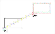
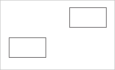
You specify a base point (P1 in the diagram) and a destination point (P2) to indicate the distance and direction of the copied entities from the original entity. These points do not have to be selected on the original entity.
 The Pattern command is an effective tool to create multiple copies in a linear or circular pattern.
The CopyNested command lets you duplicate drawing entities that are contained in a Block or a Reference
Use the Clipboard to Copy and Paste entities to another drawing. See Using the Clipboard.
Access
Command: Copy
Menu: Modify > Copy
Tool Palettes: Modify > Copy
Ribbon: Home > Modify > (Flyout) Copy 
Copy, Move, Rotate, and Scale in One Operation
Use the QuickModify command to copy, move, rotate, and scale entities in one command.
You can modify the basepoint as needed.
To copy, move, rotate, and scale entities in one operation:
- Click Modify > Quick Modify (or type QuickModify).
- Specify a base point for subsequent modifications.
- In the graphics area, specify entities to modify.
- Press Enter.
- Specify an option:
- Base. Specify a new base point for subsequent modifications.
-
Copy. Specify one or more destination points to displace copies of the specified entities, then press Enter.
Use the Base sub-option to specify a new base point in between copying. Specify Exit to finish copying.
- Move. Specify the destination point.
- Rotate. Specify the rotation angle.
- Scale. Specify the scale factor.
- Undo. Withdraws the last operation.
- Repeat the previous step to perform more modifications.
- Specify Exit to end the loop of repeated operations.
Access
Command: QuickModify
Menu: Modify > Quick Modify
Ribbon: Home > Modify > (Flyout) Quick Modify 
Copying Nested Entities
Use the CopyNested command to duplicate drawing entities that are contained in a Block or a Reference and place a copy of them at a specified location.
Based on one selection, you can create multiple copies. In addition, you can create a specified number of copies in a linear pattern (see Copying Entities in a Linear Pattern).
Optionally, you can force the copied entities onto the active layer.
To copy nested entities:
- Do one of the following:
- On the ribbon, click Home > Modify > Copy Nested.
- On the menu, click Modify > Copy Nested.
- Type CopyNested at the command prompt.
- Do one of the following:
- Specify nested entities you want to duplicate and press Enter.
- Before you specify the nested entities, use the Settings option to decide whether you want to bind or insert the entities. This option determines whether dependent symbols such as Layers, LineStyles, TextStyles, DimensionStyles, and Block definitions associated with the specified entities are added to the drawing:
- Insert. Similar to the Copy command, the specified entities are copied to the current Layer without regard to dependent symbols.
- Bind. Includes the dependent symbols associated with the specified entities into the drawing.
- Do one of the following:
- Specify a source base point for the copy.
- Specify the Displacement option and provide the relative location of the copy by specifying the X, Y, and Z displacements, for example, 3,5,5. If you want to make the copy in the X and Y directions only, do not specify a Z delta. In this case, for example, specify 3,5.
This option exits the command after you specify the displacement.
- Specify the Active Layer option to force the entities onto the active layer, then specify the destination point.
This setting is preserved during the current application session until you reset it.
- Specify the Multiple option to create more than one copy, then specify the source base point.
- Do one of the following:
- Specify a destination point to displace the copy.
- Specify the Pattern option to create a specified number of copies in a linear pattern.
- If you specified to create multiple copies, specify subsequent destination points.
The copies are placed in the specified positions. If the result of a multiple copy is unexpected, specify the Undo option.
- To finish duplicating entities, press Enter.
 The Pattern command is an effective tool to create multiple copies in a linear or circular pattern.
Access
Command: CopyNested
Menu: Modify > Copy Nested
Ribbon: Home > Modify > (Flyout) Copy Nested 
Mirroring Entities
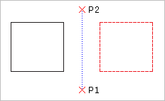
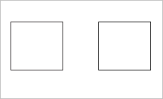
Use the Mirror command to copy selected entities onto the opposite side of a specified mirror line. To define the mirror axis, specify two points.
To mirror drawing entities:
- Click Modify > Mirror (or type Mirror).
- In the graphics area, select entities to mirror.
- Press Enter.
- Specify two points to define a mirroring axis.
To force the mirror line to be parallel to the X- or the Y-axis, enable Ortho mode.
- At the prompt, press Enter to keep the source entities or specify the Yes option to delete the entities.
The entities are mirrored about the specified axis.
Access
Command: Mirror
Menu: Modify > Mirror
Tool Palettes: Draw > Mirror
Ribbon: Home > Modify > (Flyout) Mirror 
Creating Patterns of Entities
Use the Pattern command to create copies of specified entities
- as a circular pattern, or
- in a linear pattern,
According to these types, the Pattern dialog box displays three tabs (Circular, Linear, and Path).
The copied entities inherit all properties of the original entities such as Layers, LineColors, LineStyles, and LineWeights.
3D Patterns
You can create associative and non-associative 3D linear or circular patterns.
For 3D linear patterns, you can also specify the number of levels in the Z direction.
For 3D circular patterns, you can specify the axis of rotation with any two points in space.
Circular patterns
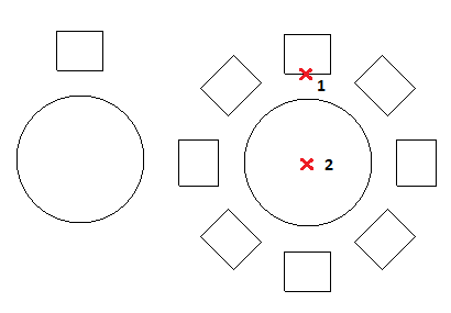
You can create a circular pattern by copying a specified entity around a specified center point. You control the number of copies. Additionally, you can rotate the copies as they are patterned, otherwise they maintain the alignment of the source entities.
The software determines the radius of the circular pattern based on the distance between the specified axis point and a base point on the specified entity. You can use a snap point as base point or you can specify another point.
Example:
A circular pattern with 8 items, fill on 360°.
To create a circular pattern:
- Do one of the following:
- On the ribbon, click Home > Modify > Pattern.
- On the menu, click Modify > Pattern.
- Type Pattern.
- In the dialog box, under Pattern type, select Circular.
- Click Specify entities
 , select the entities to generate the pattern, and press Enter to complete the selection.
The dialog box disappears when your selection is complete.
In the dialog box, the collection of specified entities is referred to as elements.
- Under Element base point, set:
- Use last entity selected. Uses the base point from the last entity you specified.
-
X and Y. Type values or click Pick base point
 to specify the base point in the graphics area.
- Under Axis point, for X and Y, type values for the center point of the pattern or click Pick center point
 .
. - Select Orient elements about axis to rotate the copies as they are patterned, otherwise they maintain the alignment of the source entities.

- Under Settings, set:
-
Base pattern on. Select an option:
- Angle Between and Total Number of Elements
- Fill Angle and Angle Between Elements
- Fill Angle and Total Number of Elements
-
Angle between (if required). Specifies the included angle between the base points of the pattern entities and the center of the pattern. Type a positive value or click Pick angle between items
 .
.
-
Fill angle (if required). Type a positive or negative value or click Pick angle to fill
 . The default for the angle to fill is 360° – a full circle pattern. A value of zero is not allowed.
- Total number (if required). Specifies the resulting number of copies in the circular patten (including the source).
- Levels. Specifies the number of levels in the 3D circular pattern.
- Spacing on levels. Specifies the distance between the levels.
-
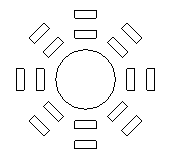
Rows. Specifies the number of rows in the circular pattern.
The following examples shows a circular pattern with two rows, each row has 8 items, fill on 360°.
- Spacing on rows. Specifies the distance between the rows within the circular pattern.
-
Base pattern on. Select an option:
- Click OK.
 Note: In the Pattern dialog box, click Preview to check the resulting pattern without creating it. You can use this option and return to the dialog box as many times as needed, then click OK to generate the pattern.
Linear patterns
You can create multiple copies of entities in a linear pattern.
You can specify the number of rows and columns and the distance between them.
To create a linear pattern:
- Do one of the following:
- On the ribbon, click Home > Modify > Pattern.
- On the menu, click Modify > Pattern.
- Type Pattern.
- In the dialog box, under Pattern type, select Linear.
- Click Specify entities
 , select the entities to generate the pattern, and press Enter to complete the selection.
The dialog box disappears when your selection is complete.
In the dialog box, the collection of specified entities is referred to as elements.
- Under Element base point, set:
- Use last entity selected. Uses the base point from the last entity you specified.
-
X and Y. Type values or click Pick base point
 to specify the base point in the graphics area.
- Under Settings, set:
- For Horizontal axis and Vertical axis, type the number of copies.
- For Levels, type the number of levels in the Z direction.
- For Spacing between elements on, define spacing between the copies and an angle for the pattern:
-
Horizontal axis. Specifies the distance between columns. Click Select column offset
 to identify the offset using two points in the drawing. If the column offset is a negative value, columns are added to the left.
-
Vertical axis. Specifies the distance between rows. Click Select row offset
 to identify the offset using two points in the drawing. If the row offset is a negative value, rows are added downward.
- Levels. Specifies the spacing between levels for 3D pattern.
-
Pattern angle. Specifies the angle to control how the copies are arranged. Click Select angle
 to specify the angle using the pointer.
-
Horizontal axis. Specifies the distance between columns. Click Select column offset
- Click OK.
 Note: In the Pattern dialog box, click Preview to check the resulting pattern without creating it. You can use this option and return to the dialog box as many times as needed, then click OK to generate the pattern.
Access
Command: Pattern
Menu: Modify > Pattern
Ribbon: Home > Modify > (Flyout) Pattern 
Tool Palettes: Modify > Pattern
Modifying Associative Patterns
Use the EditPattern command to modify the shape and appearance of associative patterns.
You can also edit associative patterns using specific EntityGrips and the Properties palette.
Entities within associative patterns retain their relationships. Associative patterns let you edit them in their entirety instead of changing the individual items in the pattern.
To make patterns associative, activate the Associative option in the Settings section of the Pattern dialog box.
To modify associative patterns using the Pattern dialog box:
- Do one of the following:
- On the ribbon, click Home > Modify > Edit Associative Pattern.
- On the menu, click Modify > Edit Associative Pattern.
- Type EditPattern.
- In the graphics area, specify an associative pattern and press Enter.
The Pattern dialog box opens with the tab that corresponds to the the pattern type you selected (circular or linear).
- Under Options, use the following:
-
Edit source. Click Select in graphics area
 to specify one of the pattern elements as a source entity to modify. Use the ClosePattern command to finish editing the pattern source entities.
- Replace elements. Replaces the source entities for specified pattern elements or for all elements referencing the original pattern source entities.
- Reset. Restores erased pattern elements and removes any element overrides.
-
Edit source. Click Select in graphics area
- Click OK.
To modify associative patterns using EntityGrips and the Properties palette:
- Make sure that EntityGrips (EGrips) are enabled. Type EntitiyGrips to set EGrip options.
- In the graphics area, select an associative pattern.
- Use grips to to modify the pattern.
| Icon | EGrip | Description | Applies to |
|---|---|---|---|
 |
Move | Moves the pattern | Applies to linear patterns |
 |
Radius | Changes the base radius of the pattern | Applies to circular patterns |
 |
Column count | Specifies the number of columns in the pattern | Applies to linear and circular patterns |
 |
Row count | Specifies the number of rows in the pattern | Applies to linear and circular patterns |
 |
Column spacing | Specifies the spacing between the elements of the columns in the pattern | Applies to linear and circular patterns |
 |
Row spacing | Specifies the spacing between the rows of the columns in the pattern | Applies to linear and circular patterns |
 |
Rotate | Changes the base radius of the pattern | Applies to circular patterns |
 |
Number of elements | Changes the vertical or horizontal elements in the pattern | Applies to linear patterns |
 |
Number of elements | Changes the polar elements in the pattern | Applies to circular patterns |
| Tangent direction | Changes the tangent direction for patterns along a path | Applies to path patterns |
Applies to all patterns
The Properties palette is displayed at the same time. Modify the parameters for the specified associative pattern as needed.
Note: To undo the associativity of patterns, use the Explode command.
Access
Command: EditPattern
Menu: Modify > Associative Pattern
Ribbon: Home > Modify > (Flyout) Edit Pattern 
Creating Offsets of Entities
Use the Offset command to create parallel shapes of Lines, 2D Polylines, Circles, Arcs, Ellipses, Elliptical Arcs, Splines, Rays, and InfiniteLines. A copy of a selected entity is placed at a specified distance from the original entity. The original entity stays in position.
The offset depends on the type of drawing entity:
- Lines: Creates identical copies and moves in the direction and distance you specify.
- Circles, Arcs, and Ellipses: Creates and scales copies using the center of the entity as a base point for scaling. You can create concentric Circles and Arcs with radii smaller or larger than the original entities.
To create offsets of entities:
- Click Modify > Offset (or type Offset).
- Type an offset distance between the source and target entity or specify an option:
- Delete. Removes the original entity when the copy of the entity is placed.
- Distances. Creates multiple offsets. Select an entity to offset, and click on the side of the entity to offset. Specify the first distance and second point. Then you can specify additional offsets.
- Destination layer. Specifies whether the entity is to be copied on the active Layer or source Layer.
- Through point. Creates an offset entity passing through a point you specify.
-
Gap type. Specifies the gap type to fill potential gaps in offset polylines:
- Arc. Fillets gaps. The fillet radius is equal to the offset distance.
- Chamfer. Chamfers gaps. The perpendicular distance from each chamfer to its corresponding vertex on the source linear polyline segment is equal to the offset distance.
- Natural. Extends linear polyline segments to their projected intersections.
- Select the entity to offset.
- Specify the side for the new entity or specify an option:
- Both sides. Creates an offset entity on both side of the source entity.
- Multiple. Creates several entities on the specified side of the source entity.
- To reverse the previous offset without terminating the running Offset command, specify the Undo option.
- Specify more offsets or specify the Exit option to end the command.
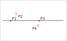
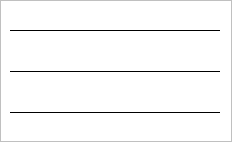
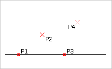
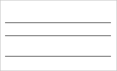
Access
Command: Offset
Menu: Modify > Offset
Ribbon: Home > Modify > Offset
Tool Palettes: Modify > Offset
Toolbar: Offset
Moving and Rotating Entities
You can move entities to a different location within a drawing, or change their orientation.
This section discusses:
- Moving Entities
- Moving Entities Incrementally
- Flipping Entities
- Rotating Entities
- Aligning Entities
- Aligning a Set of Specified Entities
Moving Entities
Use the Move command to reposition drawing entities within the coordinate system without changing their orientation or size.
To move entities:
- Click Modify > Move (or type Move).
- Specify one or more entities to move and press Enter to complete your selection.
- Specify a base point and target point to move the entities by the specified amount.
You can instead type Displacement at the prompt and provide the relative location of the copy by specifying the X, Y, and Z displacements. If the move is to be made in the X and Y directions only, do not specify a Z delta.
The entities move as specified.
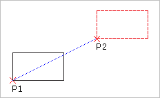
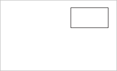
Access
Command: Move
Menu: Modify > Move
Context Menu: Specify entities, right-click in the graphics area, and click Move.
Tool Palettes: Modify > Move
Ribbon: Home > Modify > (Flyout) Move 
Moving Entities Incrementally
Use Shift + Arrow keys to move selected entities according to a specified increment.
The incremental move behavior is dependent on the active Snap mode:
- Snap is OFF:
Entities move orthogonally with the increment specified for the arrow key movement and independently from the view direction or the CCS orientation.
You can specify the arrow key increment in the Options dialog box under Drawing Settings > Arrow Key Movement.
- Snap is ON:
Entities move with the increment determined by the Snap spacing and relatively to the view direction and the CCS orientation.
You can specify the Snap spacing in the Options dialog box under User Preferences > Drafting Options > Pointer Control > Snap Settings.
Note: You can use Shift + Arrow keys to move entities in Sheet viewports.
To move entities incrementally:
- Specify the entities to move.
- Press Shift + Arrow keys.
To speed up or slow down the move, press Shift + PgUp or Shift + PgDn, where appropriate several times.
Flipping Entities
Use the Flip command to create a mirror copy of entities, deleting the source entities.
The command contrasts to the Mirror command in that entities do not remain in their original positions when they move across the mirror axis. Instead they maintain the same relative position to the symmetry axis, but flip about the specified mirror axis.
You can define the reflection axis freely by specifying two points.
Use Ortho mode to force the mirror line to be parallel to the X- or the Y-axis of the coordinate system.
To flip drawing entities:
- Type Flip at the command prompt.
- In the graphics area, select entities to flip.
- Press Enter.
- Specify two points to define the mirroring axis.
The entities are mirrored about the specified axis and flipped. The source entities are deleted.
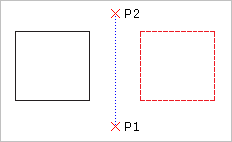
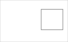
 Use Ortho mode to force the mirror line to be parallel to the X- or the Y-axis of the coordinate system.
Access
Command: Flip
Rotating Entities
Use the Rotate command to rotate entities through an angle, about a base point.
To rotate entities:
- Click Modify > Rotate (or type Rotate).
- In the graphics area, select entities to rotate.
- Press Enter.
- Specify the pivot point.
The pivot point is the point about which rotation occurs, typically a corner or a center of an entity. If the base point is the corner of a specified entity, the entities rotate on that corner. If the base point is the center of a specified entity, the entity stays in the same relative position, but spins about the base point.
- Enter the rotation angle or specify an option:
-
Reference. Specify a reference angle, then enter the new angle.
To specify the new angle in the graphics area, specify the Point option.
The selected entities rotate as specified.
-
Copy. Creates a copy of the specified entities.
To create multiple copies, specify the Multiple option, then specify new reference angles.
To finish duplicating entities, press Enter.
-
Reference. Specify a reference angle, then enter the new angle.
 When you rotate, set the Ortho mode to constrain the angle of rotation to 90° intervals.
Access
Command: Rotate
Menu: Modify > Rotate
Tool Palettes: Modify > Rotate
Ribbon: Home > Modify > (Flyout) Rotate 
Aligning Entities
The Align command aligns entities with respect to other entities or other target points on 2D planes or in 3D space.
The command combines the Move and Rotate commands or the Move and Rotate3D commands. If necessary, you can scale 2D aligned entities to fit their new location.
To align entities using one pair of points:
Specifying only one pair of points moves the specified entities without rotating them.
- Click Modify > Align (or type Align).
- In the graphics area, select entities to align.
- Press Enter.
- In the graphics area, specify the first source point and the destination point, or type values to set the points. Use EntitySnaps where appropriate.
- Press Enter.
To align entities using two pairs of points:
Specifying two pairs of points performs the move and rotation based on the current coordinate system. The first pair of source and target points defines the movement vector, the second pair of points defines the rotation angle.
If the distance between the first and second source point and the first and second target point is not identical, you can scale the aligned entity to fit between the two destination points.
- Click Modify > Align (or type Align).
- In the graphics area, select entities to align.
- Press Enter.
- In the graphics area, specify the first source point and the destination point, or type values to set the points. Use EntitySnaps where appropriate.
- Repeat step 4 for the set of second points.
- Press Enter.
- Specify whether to scale the entities based on the alignment points.
- Press Enter.
To align entities using three pairs of points:
Specifying three pairs of points moves the first source point of the entity to the first destination point, the second source point to the second destination point, and the third source point to the third destination point.
- Click Modify > Align (or type Align).
- In the graphics area, select entities to align.
- Press Enter.
- In the graphics area, specify the first source point and the destination point, or type values to set the points. Use EntitySnaps where appropriate.
- Repeat step 4 for the second and third points.
 The Align3D command lets you first specify the source points, then follow up with the destination points.
Access
Command: Align
Menu: Modify > Align
Ribbon: Home > Modify > (Flyout) Align 
Aligning a Set of Specified Entities
Use the AlignX command to align a set of specified entities according to the first selected one.
You can align the following entities:
- Splines, Polylines, and Lines
- Arcs, Circle, Ellipses, and elliptical Arcs
- Text entities (Notes and SimpleNotes)
- Hatches, Images, and Blocks
- Dimensions
To align a set of specified entities:
- Do one of the following:
- On the ribbon, select Home > Modify > AlignX.
- On the menu, click Modify > AlignX.
- Type AlignX.
- In the graphics area, choose a suitable entity and select it.
- Select all other entities to align and press Enter.
- Specify an alignment option:
- Top
- Bottom
- Left
- Right
- Vertical Center
- Horizontal Center
- Center
The entities are aligned to the specified side of the first entity that you have selected.
- Press Enter.
Examples:
- First selected entity: the green circle
- Alignment: Top

- First selected entity: the blue circle
- Alignment: Bottom

- First selected entitiy: the blue circle
- Alignment: Horizontal Center

Access
Command: AlignX
Menu: Modify > AlignX
Ribbon: Home > Modify > (Flyout) Align X 
Changing the Size and Shape of Entities
You can adjust the length of existing entities.
This section discusses:
- Scaling Entities
- Stretching Entities
- Changing the Length of Entities
- Trimming Entities
- Trimming Entities with Power Trim
- Extending Entities
Scaling Entities
Use the Scale command to enlarge or reduce entities while keeping proportions the same.
To scale entities:
- Click Modify > Scale (or type Scale).
- In the graphics area, select entities to scale.
- Press Enter.
- Specify the base point.
The base point, if part of the specified entities, holds its original position during scaling, while all other points move by the same relative values in the direction of the X-, Y-, and optional Z-axis. For the base point, you can instead select a point not on an existing entity. In this case, the distance from the base point to all other points making up the entity change by the same scale factor.
- Enter the scale factor or specify the Reference option to enter a reference length and a new length. Optionally, specify the Points option to represent the reference length as two points.
A scaling factor larger than 1 enlarges the entities by this factor. A scaling factor between 0 and 1 reduces the entities by this factor. For instance, the factor 3 enlarges the selected entities three times, while the factor 0.25 reduces the entities to a quarter of their original size.
Use Reference to specify an exact change in the lengths of entities. For example, to enlarge an entity with a side length of 3.45 drawing units up to 3.54, you have to calculate the scaling factor. With Reference, however, you specify the reference length (3.45) and the new length (3.54).
Access
Command: Scale
Menu: Modify > Scale
Tool Palettes: Modify > Scale
Ribbon: Home > Modify > (Flyout) Scale 
Stretching Entities
Use the Stretch command to change the position of an entity’s nodes, while retaining their relation to other nodes in the entity. Stretching enlarges or reduces entities in only one direction, unlike scaling. Use stretching also to move single entities inside of a contour.
During stretching, the selection method determines whether entities move or stretch.
- All entities that lie completely in the selecting window move.
- All entities intersecting the selection window or polygon stretch or shrink by modifying the end points within a crossing window or polygon, leaving the other end points in their original location.
- All other drawing entities retain their positions and shapes.
You can stretch Lines, PolyLine segments, Rays, Arcs, elliptical Arcs, and Splines.
To stretch entities:
- Click Modify > Stretch (or type Stretch).
- In the graphics area, select entities to stretch.
Use a crossing window or polygon to enclose the nodes to stretch. After you select entities using this method, you can specify the Remove option to erase entities from the selection set. After erasing entities, press Enter.
- Press Enter.
- Specify a from point and destination point to define the distance to stretch the entities.
The entities stretch as specified.
To stretch entities using displacement:
- Click Modify > Stretch (or type Stretch).
- In the graphics area, select entities to stretch.
Use a crossing window or polygon to enclose the nodes to stretch. After you select entities using this method, you can specify the Remove option to erase entities from the selection set. After erasing entities, press Enter.
- Press Enter.
- Specify the Displacement option to stretch specified entities by a vector. Provide the relative location of the stretched entities by specifying the X, Y, and Z displacements. If stretching is to be done in the X and Y directions only, do not specify a Z delta.
– or –
Specify a from point, then press Enter to Use from point as displacement.
The entities stretch as specified.
To stretch a single entity using EntityGrips:
- In the graphics area, select entities to stretch.
- Click one of the EntityGrips.
- Move the pointer to another location and click.
To stretch multiple entities using EntityGrips:
- In the graphics area, select entities to stretch.
- Hold down Shift and click several EntityGrips.
- Release Shift and click one EntityGrip as the base grip.
- Move the pointer to another location and click.
Access
Command: Stretch
Menu: Modify > Stretch
Tool Palettes: Modify > Stretch
Ribbon: Home > Modify > (Flyout) Stretch 
Changing the Length of Entities
Use the EditLength command to change the length of linear or curved entities and the included angle of Arcs. You can lengthen or shorten Lines, open PolyLines, Arcs, and elliptical Arcs.
Unlike the Extend and Trim commands, EditLength works without a boundary edge. It extends or trims an entity to a specific value or a ratio of its original size. You can also use dynamic dragging to change the length of entities. The command changes the length of an entity in its existing direction and at the end point closest to the selection point.
To change the length of an entity:
- Click Modify > Change Length (or type EditLength).
- In the graphics area, select an entity or specify an option:
- Dynamic: Lets you specify an entity, drag it to its new length, and click to fix the length.
- Increment: Extends or reduces the endpoint of an entity by the distance you specify using the keyboard or by clicking two points. Specify a positive delta to increase or a negative delta to decrease the length. Specify the Angle option to increase or decrease the included angle.
- Percent: Lengthens or reduces by a defined ratio of the original size. For an Arc, the percentage is based on its circumference. 200% doubles the length of the Line or Arc; 50% reduces it by half.
- Total: Changes the total length of a Line or Arc to the specified dimension. The current length of the specified entity displays in parentheses. Specify the Angle option to increase or decrease the included angle.
- Change the length of more entities or press Enter.
Access
Command: EditLength
Menu: Modify > Change Length
Ribbon: Home > Modify > (Flyout) Change Length 
Trimming Entities
Use the Trim command to cut drawing entities precisely at the edges defined by one or more entities.
Consider the following:
- Use Lines, InfiniteLines, Rays, PolyLines, RichLines, Circles, Arcs, Ellipses, Splines, and Hatches as cutting edges to trim the selected entities.
- You can trim Hatches at cutting edges, but you cannot trim Hatches at Hatches. Trimmed Hatches maintain associativity with changed boundary entities, even if they are divided into different hatched areas. Divided Hatches remain as one entity, but you can use the EditHatch command to separate them into individual entities (dialog box option Create Hatch for each boundary). The same applies to Gradients.
- You cannot trim Notes, SimpleNotes, Regions, or Blocks, but you can use them as cutting edges.
- To trim intersecting and adjoining RichLines, use the EditRichLine command.
- When you select a PolyLine as a cutting edge, the command trims at its centerline.
- When you select a RichLine as a cutting edge, the command trims at the first intersecting line.
- On Sheets, Viewports can be cutting edges.
To trim entities:
- Do one of the following:
- On the ribbon, click Home > Modify > Trim.
- On the menu, click Modify > Trim.
- Type Trim.
- In the graphics area, select entities to make up the cutting edge.
Note: If you specified a RichLine, the command trims the entities at the first intersecting line.
- Press Enter.
- In the graphics area, select entities on the side that you want to trim or specify options:
- Crossing. Selects entities within and crossing a rectangle determined by two opposite points. If a crossing selection is not distinct, Trim resolves the selection by following the defined rectangle clockwise from the first point to the first entity encountered.
- Crossline. Uses the fence selection method to trim the entities on the side the fence line crosses.
-
Behavior. When using the command for a large number of entities, lets you reduce the set of entities taken into account as trimming cutting edges.
- Standard. Considers all specified entities as cutting edges.
- Fast. When selecting all entities as cutting edges, considers only visible entities from the current view.
- Edge. Trims to a a cutting edge that if extended, intersects the entity. The entities to trim do not have to actually intersect cutting edges. To trim at an implied intersection, specify the Edge option followed by the Extend option.
- Erase. Deletes entities without exiting the Trim command.
- Project. Sets the projection mode to CCS (the X-Y plane of the active Custom Coordinate System), None, or View.
- Undo. Reverses the most recent trim operation.
- Fence. Trims the entities on the side the fence line crosses.
- Shift + select. Extends entities while you hold down Shift and select entities.
- Press Enter.
Example:
Entities trimmed at a RichLine
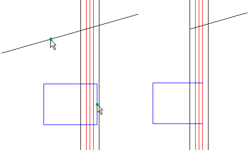
The pointer selections are shown on the left. The result is on the right.
Extending RichLines
Trimming RichLines
To trim RichLines:
Trimms only if the cutting entity intersects all lines of the RichLine.
To trim RichLines at RichLines:
- Do one of the following:
- On the ribbon, click Home > Modify > Trim.
- On the menu, click Modify > Trim.
- Type Trim.
- In the graphics area, select the first RighLine to make up the cutting edge.
- Press Enter.
- In the graphics area, select the RichLine on the side that you want to trim.
- Specify an option:
- Closed.
- Open.
- Merged.
Access
Command: Trim
Menu: Modify > Trim
Tool Palettes: Modify > Trim
Ribbon: Home > Modify > (Flyout) Trim 
Trimming Entities with PowerTrim
Use the PowerTrim command to trim multiple, adjacent entities by dragging the pointer across each entity.
You can also extend entities along their natural paths, and extend or trim two entities where they intersect at a virtual corner.
Consider the following:
- You can trim Lines, PolyLines, Arcs, Circles, Ellipses, Splines, Rays, InfiniteLines, RichLines, Hatches, and Gradients.
- Trimmed Hatches maintain associativity with changed boundary entities, even if they are divided into different hatched areas.
The same applies to Gradients.
- You cannot trim Dimensions, Notes, SimpleNotes, Regions, or entities within Blocks, but these entities are recognized as cutting edges.
- When you trim at a wide PolyLine, the command trims at its centerline.
- When you trim at a RichLine, the command trims at its first intersecting line.
- On Sheets, you can trim at Viewport boundaries.
Note: If your drawing contains RichLines, you can control the way they intersect.
PowerTrim
To trim entities with PowerTrim:
- Do one of the following:
- On the ribbon, click Home > Modify > Power Trim.
- On the menu, click Modify > Power Trim.
- Type PowerTrim, then specify the Powertrim option.
- In the graphics area, click and drag the pointer over the entity to trim.
The pointer changes to
 as it crosses and trims the entity. A trail is created along the trim path.
Note: When trimming RichLines, the trail must intersect all the lines of the RichLine. Otherwise, the command has no effect.
- Continue to press the mouse button and drag across each entity you want to trim.
- Release the mouse button when finished trimming.
- Press Enter.


The pointer movement is shown in green. The result is on the right.
 Note: If you drag across an entity that does not intersect other entities, the entity is deleted. You can use this behavior intentionally.
To extend entities with PowerTrim:
- Do one of the following:
- On the ribbon, click Home > Modify > Power Trim.
- On the menu, click Modify > Power Trim.
- Type PowerTrim, then specify the Powertrim option.
- Press Shift, then click in the graphics area next to the first entity, and drag across the entity to extend.
The pointer changes to
 as it crosses and extends the entity. A trail is created along the trim path.
Note: When extending RichLines, the trail must intersect all the lines of the RichLine. Otherwise, the command has no effect.
- Continue to press the mouse button and drag across each entity to extend.
- Release the pointer when finished extending.
- Press Enter.
To lengthen and shorten entities with PowerTrim:
- Do one of the following:
- On the ribbon, click Home > Modify > Power Trim.
- On the menu, click Modify > Power Trim.
- Type PowerTrim, then specify the Powertrim option.
- Move the pointer to an entity so that the pickbox appears, then click the entity.
- Drag the entity to its new length, then click to fix the length.
- Press Enter.
To lengthen and shorten entities to boundary edges with PowerTrim:
- Do one of the following:
- On the ribbon, click Home > Modify > Power Trim.
- On the menu, click Modify > Power Trim.
- Type PowerTrim, then specify the Powertrim option.
- Move the pointer to an entity so that the pickbox appears, then click the entity.
- Specify another entity that acts as a boundary.
Note: This method lets you lengthen or shorten an entity to an invisible extension of another entity. Sub-entities of Blocks and References are recognized as boundaries.
- Press Enter.


The pointer selections are shown on the left. The result is on the right.
Corner Trim
To trim entities with the Corner option:
- Do one of the following:
- On the ribbon, click Home > Modify > Corner Trim.
- On the menu, click Modify > Power Trim.
- Type PowerTrim, then specify the Corner option.
- Specify the first entity to join on the side to remain.
- Specify the second entity to join.
- Press Enter.
Note: Depending on the entities and their relative position to each other, the software extends or trims each entity to join them. A message appears if the operation cannot be completed.


The pointer selections are shown on the left. The result is on the right.
 Use the Undo option to cancel the most recent trim operation. You can use the Undo option repeatedly.
Access
Command: PowerTrim
Ribbon: Home > Modify > Power Trim, and Modify > Corner Trim
Menu: Modify > Power Trim, and Modify > Corner Trim
Extending Entities
Use the Extend command to edit entities so they have common boundary edges. Extend expands parts of entities to the intended boundary edge, letting you close polygons precisely or extend entities to the proper boundary edge. As drawing a entity expands, they do not change direction. A Line remains a Line, and an Arc remains an Arc.
To extend entities:
- Click Modify > Extend (or type Extend).
- In the graphics area, select entities to make up the boundary edges.
The Extend operation does not affect these entities.
- Press Enter.
- In the graphics area, select the entity to extend or specify an option:
- Crossing. Selects entities within and crossing a rectangle determined by two opposite points. If a crossing selection is not distinct, Extend resolves the selection by following the defined rectangle clockwise from the first point to the first entity encountered.
- Crossline. Uses the fence selection method to extend the selected drawing entities.
- Edge. Extends to a boundary edge that if extended, intersects the entity. The entities to extend do not have to actually intersect the boundary edge. To stretch to an implied intersection, select Edge followed by Extend.
- Erase. Deletes unneeded entities without exiting the Extend command.
- Project. Sets the projection mode to CCS (the X-Y plane of the current custom coordinate system), None, or View.
- Undo. Reverses the most recent extend operation.
- Fence. Uses the fence selection method to extend the selected drawing entities.
- Shift + select. Lets you trim entities while you hold down Shift and select entities to trim.
After you select entities, the selected entities are extended.
If there is more than one way to extend an entity, the expansion of the selected entity occurs from the end point nearest to the pointer when you select the entity. If more than one boundary edge lies in the direction of the entity to extend, the entity is extended to the first boundary edge first.
Clicking a second time continues the expansion to the second boundary edge.
- Press Enter.
Access
Command: Extend
Menu: Modify > Extend
Ribbon: Home > Modify > (Flyout) Extend 
Tool Palettes: Modify > Extend
Fillets and Chamfers
You can change the shape of entities corner.
This section discusses:
Applying Chamfers
Use the Chamfer command to connect two Lines with a beveled corner. The selected entities do not have to intersect and they can overlap. If the entities overlap, they are trimmed to create the beveled corner.
You can specify a chamfer distance from the corner of adjacent Lines of both entities for nonsymmetrical chamfers. You can also define the connecting Line using a length and an angle.
Use Chamfer in plan view because chamfering operates on selection points and end points of entities.
 If you chamfer two Lines and both Lines are on the same Layer, the command places the chamfer Line on that Layer. If the Layers of the Lines differ, the command places the chamfer Line on the current Layer.
To apply chamfers:
- Click Modify > Chamfer (or type Chamfer).
- In the graphics area, select the first Line or specify an option:
- Angle. Sets a chamfer length on the Line you first select and an angle for the second Line to create a chamfer Line.
- Distance. Sets the chamfer distances. The default value for the first chamfer distance is the most recently used distance. The default value for the second distance is the value specified for the first chamfer distance. If you specify zero for both chamfer distances, the two Lines extend until they meet, if possible. In this way, the command implements an intersection and does not draw a chamfer Line.
- Method. Indicates whether to use two distances (specified by the Distance option) or a length and an angle (specified by the Angle option) as the default for creating the chamfer.
- Multiple. Lets you apply chamfers to multiple entities. By default, you complete a single chamfer. You are prompted repeatedly to select a first and a second entity to chamfer until you press Enter to complete the command. You can then change the chamfer distances or toggle the trim mode between chamfer operations.
- Polyline. Lets you chamfer PolyLines treated as a single entity. The command chamfers all vertices of a PolyLine or polygon in one step and inserts chamfers at each vertex of the PolyLine where two Lines meet, if applicable. The Polyline option prompts for a 2D PolyLine, then reports the number of Lines processed and the number of Lines too short to be chamfered. The generated chamfer segments become part of the PolyLine.
- Trim mode. Indicates whether to erase the Line segments that lie beyond the chamfer.
- Undo. Reverses the previous chamfer, only if Multiple mode is active.
- Select the second Line.
You can instead apply an acute corner by pressing Shift and specifying the second drawing entity. This method creates acute corners without changing the chamfer distances to join two end points.
Access
Command: Chamfer
Menu: Modify > Chamfer
Ribbon: Home > Modify > (Flyout) Chamfer 
Tool Palettes: Modify > Chamfer
Applying Fillets
Use the Fillet command to create rounded corners by replacing parts of two Lines with an Arc. The filleted entities do not have to intersect, and they can overlap. If the entities overlap, they are trimmed to create the rounded corner and the Lines to be filleted are connected to the fillet Arc.
A fillet radius of 0 creates acute instead of rounded corners. Press Shift while selecting entities to override the current fillet radius with a value of 0.
To apply fillets:
- Click Modify > Fillet (or type Fillet).
- In the graphics area, select the first entity whose intersection is to be filleted, or specify an option:
- Multiple: Lets you apply fillets to multiple entities. By default, you complete a single fillet. You are prompted repeatedly to select a first and a second entity to fillet until you press Enter. You can then change the fillet radius or toggle the trim mode between fillet operations.
- Polyline: Lets you fillet PolyLines treated as a single entity. The command fillets all vertices of a PolyLine or Polygon in one step and inserts fillet Arcs at each vertex of the PolyLine where two Lines meet, if applicable. The Polyline option prompts for a 2D PolyLine, then reports the number of Lines processed and the number of Lines too short to be filleted.
- Radius: Defines the radius for the fillet Arc. Changing the radius does not affect previously created fillet Arcs.
- Trim mode: Indicates whether to erase the Line segments that lie beyond the fillet Arc.
- Undo: Reverses the previous fillet, only if Multiple mode is active.
- Select the second entity.
- – or –
- Press Shift and select an entity to apply a corner to. The selected entities are lengthened or shortened to intersect without a filleting Arc. This method creates acute corners without changing the fillet radius.
Access
Command: Fillet
Menu: Modify > Fillet
Ribbon: Home > Modify > (Flyout) Fillet 
Tool Palettes: Modify > Fillet
Modifying Complex Entities
Additional editing operation let you split and join entities such as Lines, open PolyLines, Arcs, elliptical Arcs, or open Splines.
This section discusses:
- Editing Polylines
- Editing Polyline Vertices
- Editing Splines
- Converting Polylines
- Modifying RichLines
- Modifying RichLines Using Common Editing Commands
- Welding Entities
- Splitting Entities
- Exploding Complex Entities
Editing PolyLines
Use the EditPolyLine command to edit PolyLines, PolyLine vertices, and 3D PolygonMeshes by:
- Opening a closed PolyLine or closing an open PolyLine
- Joining a PolyLine with other drawing entities such as Lines, Arcs, or PolyLines
- Changing the width of the whole PolyLine and tapering the entire PolyLine
- Editing the control points (vertices) of individual PolyLine segments
 You can perform many edits of one or more PolyLines with a single EditPolyLine command. If you revert PolyLine editing with a subsequent Undo command, all the working steps are reverted.
To edit PolyLines:
- Do one of the following:
- On the ribbon, click Home > Modify > Edit PolyLine.
- On the menu, click Modify > Entity > PolyLine.
- Type EditPolyLine.
- In the graphics area, select a PolyLine, or specify the Multiple option to select a group of PolyLines and press Enter.
If a selected Line or Arc is not a PolyLine, you have the option to convert it to one. You can also use this method to turn a series of individual but connected Lines, Arcs, and PolyLines into a single PolyLine. In a single EditPolyLine command, you can first convert a Line or Arc into a PolyLine. Then use the Join option to add other entities to the PolyLine.
- Specify an option:
- Close / Open. The option displays Close if the PolyLine is open and Open if the PolyLine is closed. The option Back is also available after a polyedit operation. Specify Close to join the start and end points of the PolyLine with a straight PolyLine segment. The width of this segment is the width of the end point of the last drawn PolyLine. Specify Open to delete the PolyLine segment between the start and end points.
- Decurve. Reverts a PolyLine curve created using Fit or Spline to its original vertices.
-
Edit vertex. Lets you edit the marked vertex by using a vertex editing option. You can also use EntityGrips for some of the options, such as Move. If you specified the Multiple option, you cannot use the Edit vertex option.
- Add vertex to midpoint. Inserts an additional vertex at the midpoint of the next segment.
- Convert to arc / Convert to line. Converts the next PolyLine segment to an arc if it is a linear segment or to a line if it is a curved segment. If you convert a linear segment to an arc segment, specify a point to force the arc to pass through.
- Insert. Inserts a new vertex. Specify the location.
- Move. Moves the current vertex. Specify the position.
- Next. Proceeds to the next vertex and makes it active.
- Previous. Returns to the previous vertex and makes it active.
- Regen. Regenerates the PolyLine.
- Split. Divides the PolyLine into two parts, similar to the Split command.
- Straighten. Deletes vertices.
- Tangent. Specifies a tangent direction for the vertex when you specify the Fit option during PolyLine editing.
- Width. Specifies a start and end width for the PolyLine segments that start at the active vertex. To see the effect, use the Regen option.
- Exit. Exits Edit vertex mode.
- Fit. Turns the PolyLine into a smooth curve consisting of arcs joining each pair of vertices, resulting in an arc-fit PolyLine. Unlike the Spline option, the curve passes through all vertices of the PolyLine.
-
Join. Merges Lines, Arcs, and other PolyLines with the selected PolyLine. Select the drawing entity to join. The PolyLine to edit and the entity to join must meet exactly at one end point.
If you specified the Multiple option initially, specify the gap tolerance to join PolyLines that do not touch. Use the Join type sub-option to specify how the gap is closed:
- Extend. Extends or trims the PolyLine segments to the nearest endpoints that lie within the gap tolerance.
- Add. Adds a straight segment between the two nearest endpoints that lie within the gap tolerance.
- Both. Extends or trims the PolyLine segments, if possible. Otherwise, adds a straight segment between the two nearest endpoints.
- Linegen (line generation). Specifies whether to use a continuous or dashed LineStyle around the vertices for PolyLines with noncontinuous LineStyles. Specify No to place breaks between dashes in LineStyles so they are positioned properly at corners. Specify Yes to set the LineStyle to a fluent pattern around the vertices of the PolyLine.
- Reverse. Reverses the direction of the PolyLine. The end point is now the starting point, the second to last vertex the second vertex, and so on.
- Spline. Turns the PolyLine into a curve using the vertices as control points. Unlike the Fit option, the curve usually does not pass through the vertices. Note: Curves created with the Spline option are not true splines in the mathematical sense. To create genuine splines, use the Spline command.
- Taper. Tapers the width of the PolyLine from the start point to the end point. Specify the width at the starting point, then the width at the endpoint of the PolyLine.
- Undo. Reverses the most recent operation without exiting the command.
- Width. Specifies one width to make PolyLines uniform for all segments, including those with different start and end widths. Specify the width by typing a value or using the pointer.
- Exit. Exits the EditPolyLine command.
 To fillet a PolyLine, use the Fillet command. To chamfer a PolyLine, use the Chamfer command.
Access
Command: EditPolyLine
Menu: Modify > Entity > PolyLine
Ribbon: Home > Modify > (Flyout) Edit PolyLine 
Tool Palettes: Modify > Edit PolyLine
Editing Splines
After you create a Spline, you can change its shape using various methods:
- Use grip points to move, add, or delete control vertices and fit points. Additionally, you can change the tangent direction of the spline at its end points.
 The triangular grip point lets you switch between control vertices and fit points.
Control vertices Fit points 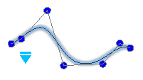
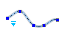
- Use the EditSpline command to edit Splines.
You can:
- Close open Splines
- Join Splines with other 2D entities
- Convert Splines to Polylines
- Edit fit point data and control frame data
- Edit properties and parameters of Splines
Note: The Properties palette groups several options for modifying Splines.
To edit Splines:
- Do one of the following:
- On the ribbon, click Home > Modify > Edit Spline.
- On the menu, click Modify > Entity > Spline.
- Type EditSpline.
- In the graphics area, specify a Spline.
- Specify an option:
-
Close. Closes open Splines.
This option displays only if the Spline is open. A closed Spline forms a loop.
- Fit data. Edits fit point data.
-
Edit vertex. Edits control frame data.
See Editing Control Frame Data of Splines (Control Vertex Editing).
-
Join. Connects a specified Spline with a line, arc, Polyline, elliptical arc, or other Spline at a coincident endpoint to form an extended Spline.
Specify the connected entity to combine it with the specified Spline.
This option is not available if you specified a closed Spline.
-
Polyline. Turns the Spline into a Polyline using the vertices as control points.
Specify the precision value that determines how closely the resulting Polyline matches the Spline. Valid values are any integer between 0 and 99. The default value is 9.
-
Reverse. Reverses the direction of the Spline.
This option is mainly intended for application developers.
- Undo. Undoes the most recent operation without terminating the command.
- Exit. Ends the command.
-
Close. Closes open Splines.
- Repeat step 3 as needed, or press Enter to end the command.
Editing Fit Point Data of Splines (Fit Point Editing)
The Fit data option of the EditSpline command lets you apply the following options:
- Add. Adds fit points to the specified Spline.
-
Close. Closes open Splines.
This option displays only if the Spline is open.
- Delete. Removes specified fit points.
-
Kink. Adds knots and fit points at specified locations.
Note: The Spline does not maintain tangent or curvature continuity at the specified location.
-
Move. Moves specified fit points to new locations. Specify a new fit point or specify options:
- Next. Proceeds to the next fit point and makes it active.
- Previous. Returns to the previous fit point and makes it active.
-
Specify point. Lets you specify a fit point and makes it active.
Temporarily disable the EntitySnap modes to prevent them from snapping to the end points of the Spline instead of the fit points.
- Exit. Exits the Move mode.
- Purge. Removes the fit points from the Spline and creates control vertices instead.
-
Tangents. Lets you specify the Start Tangency and the End Tangencyof the Spline.
These point specifications determine the tangent conditions on the start point and on the endpoint of the Spline. Lines that are tangent to the Spline display dynamically from the start point and the endpoint of the Spline.
In some situations it is useful to apply the EntitySnaps Parallel and Perpendicular to specify the tangent direction.
Confirm System default to let the application calculate the default end tangents.
- Tolerance. Adjusts the Spline to the existing fit points using a new tolerance value.
- Exit. Return to the main prompt level.
Editing Control Frame Data of Splines (Control Vertex Editing)
Use the Edit vertex option of the EditSpline command to add and remove control vertices and modify the control frames parameters of Splines:
- Add. Adds a new control vertex at the point you specify that is located between two existing control vertices.
- Delete. Removes a specified control vertex.
- Elevate order. Increases the polynomial order (degree plus one) of the Spline. This option creates a higher number of control vertices across the Spline. The maximum value is 26.
-
Move. Relocates specified control vertices. Specify a new vertex locations or specify options:
- Next. Proceeds to the next vertex and makes it active.
- Previous. Returns to the previous vertex and makes it active.
-
Specify point. Lets you specify a control vertex and makes it active.
Temporarily disable the EntitySnap modes to prevent them from snapping to the end points of the Spline instead of the vertices.
- Exit. Exits the Move mode.
-
Weight. Lets you change the weight of a specified control vertex.
The Spline is recalculated based on the new weight value for the specified control vertex. A larger value will move the Spline closer to the control vertex.
- Exit.Return to the main prompt level.
 Note: You can use the Spline option of the EditPolyline command to apply a cubic spline type to a 2D Polyline.
Access
Command: EditSpline
Menu: Modify > Entity > Spline
Ribbon: Home > Modify > (Flyout) Edit Spline 
Tool Palettes: Modify > Spline Edit
Converting PolyLines
Use the ConvertPolyLine command to convert lightweight PolyLines to heavyweight PolyLines and vice versa.
Lightweight PolyLines are optimized PolyLines compared to old-format, heavyweight PolyLines.
If you receive drawing files that originated in applications which do not support lightweight PolyLines or if you reopen legacy drawings, you may want to convert old-format PolyLines to lightweight PolyLines. On the contrary, you can convert the other way around, if you need to supply drawing files to use in applications that do not support lightweight PolyLines.
In the Properties palette, you can view the type of a selected PolyLine. It can be either PolyLine (for lightweight PolyLines), 2D PolyLine (for old-format PolyLines), or 3D PolyLine.
To convert PolyLines:
- Do one of the following:
- On the ribbon, click Home > Modify > Convert PolyLine.
- On the menu, click Modify > Entity > Convert PolyLine.
- Type ConvertPolyLine.
- Specify Heavy or Light as the target format.
- Specify the PolyLine entities to convert and press Enter.
Entities of other types are ignored.
The command reports the number of converted PolyLine entities.
 Note: You cannot convert 3D PolyLines. To convert Lines or Arcs to PolyLines, use the EditPolyLine command.
Access
Command: ConvertPolyLine
Menu: Modify > Entity > Convert PolyLine
Ribbon: Home > Modify > (Flyout) Convert PolyLine 
Modifying RichLines
Use the EditRichLine command to modify RichLines. You can edit intersecting and adjoining RichLines, break and weld RichLines, and add or delete vertices to or from existing RichLines.
To edit intersecting RichLines:
- Click Modify > Entity > RichLine (or type EditRichLine).
- In the dialog box, select Closed Cross
 , Open Cross
  , or Merged Cross
  .
. - Click OK.
- In the graphics area, specify the first of two intersecting RichLines.
- Specify the second RichLine.
-
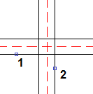
- The intersection between the two RichLines results in one of the following:
Closed Cross: Open Cross: Merged Cross: 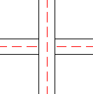
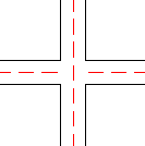
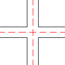
- Repeat steps 4 and 5 if necessary.
- Press Enter.
To create tee connections from two RichLines:
- Click Modify > Entity > RichLine (or type EditRichLine).
- In the dialog box, select Closed Tee
 , Open Tee
  , or Merged Tee
  .
. - Click OK.
- In the graphics area, specify the RichLine to trim or extend.
- Specify the RichLine to use as the boundary line.
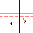
- The tee connection between the two RichLines results in one of the following:
Closed Tee: Open Tee: Merged Tee: 


- Repeat steps 4 and 5 if necessary.
- Press Enter.
To create a corner joint from two RichLines:
- Click Modify > Entity > RichLine (or type EditRichLine).
- In the dialog box, select Corner Joint
 .
. - Click OK.
- In the graphics area, specify a RichLine.
- Specify a RichLine that crosses the first RichLine.
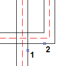
- The RichLines are trimmed or extended at their intersection.
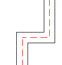
- Repeat steps 4 and 5 if necessary.
- Press Enter.
To cut RichLines:
- Click Modify > Entity > RichLine (or type EditRichLine).
- In the dialog box, select Cut Single
 to cut off a section from a single element in a RichLine, or Cut All
  to cut off a section from the entire RichLine.
 - Click OK.
- In the graphics area, specify a RichLine.
The point you click is where the break begins.
- Specify the second point to define the section to delete.

- The portion between the two points is removed:
Cut Single: Cut All: 

- Repeat steps 4 and 5 if necessary.
- Press Enter.
 You can cut off one end of a RichLine by clicking a RichLine at the point where you want the new end point, then click the other point past the RichLine’s current end point.
To weld aligned RichLines:
- Click Modify > Entity > RichLine (or type EditRichLine).
- In the dialog box, select Weld All
 .
. - Click OK.
- In the graphics area, specify a RichLine.
- Specify the RichLine to rejoin.
 Result:
- Repeat steps 4 and 5 if necessary.
- Press Enter.
To add vertices to RichLines:
- Click Modify > Entity > RichLine (or type EditRichLine).
- In the dialog box, select Add Vertex
 .
. - Click OK.
- In the graphics area, click the RichLine where you want to place new vertices.
Vertices are added at the specified points.
- Press Enter.
 To move RichLine vertices, use EntityGrips on RichLines.
To delete vertices from RichLines:
- Click Modify > Entity > RichLine (or type EditRichLine).
- In the dialog box, select Delete Vertex
 .
. - Click OK.
- In the graphics area, click the RichLine near vertices to delete.
Vertices are deleted from the specified points.
- Press Enter.
 To see RichLine vertices, turn on EntityGrips and select RichLines.
Access
Command: EditRichLine
Menu: Modify > Entity > RichLine
Modifying RichLines Using Common Editing Commands
RichLines consist of 2 to 16 parallel linear entities created as one object.
You can modify RichLines:
- Using common editing commands, such as Trimm, Extend, and Powertrim
- Using the RichLine editing command EditRichLine
- Using RichLineStyles
The RichLine editing options include:
- Add and delete vertices
- Edit corner joints
- Change the intersection style
- Split and join
Trimming and Extending RichLines
You can shorten or extend RichLines to meet the edges of other entities.
When trimming RichLines, the cutting edge entity must intersect all the lines of the RichLine. Otherwise, the command has no effect.
Example:
Trimming a RichLine
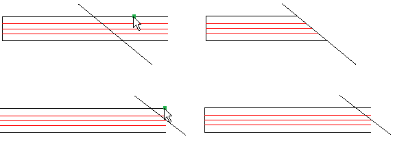
The pointer selections are shown on the left. The result is on the right.
When extending RichLines, the boundary edge must not intersect the lines of the RichLine. Othewise, the command has no effect.
Example:

Trimming RichLines at RichLines
You can shorten RichLines using a RichLine as a cutting edge. The command trims the RichLine at the first intersecting line of the RichLine used as cutting edge.
The following intersection options are available:
- Closed
- Open
- Merged
 You can use the Trim command to cleanup cross intersections of RichLines.
Example:
Intersecting RichLines
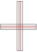
|
Closed
|
Open
|
Merged
|
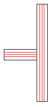 |
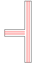 |
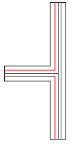 |
Extending RichLines to RichLines
You can use the Extend command to extend RichLines to meet another RichLine. The command extends the RichLine to the first intersecting line of the RichLine used as boundary edge.
The following intersection options are available:
- Closed
- Open
- Merged
Example:
RichLine to extend to another RichLine as boundary edge

|
Closed
|
Open
|
Merged
|
 |
 |
 |
Trimming and Extending RichLines Using PowerTrim
You can shorten or extend RichLines to meet the edges of other entities using the PowerTrim command.
When trimming RichLines using the Powertrim command, the trail must intersect all the lines of the RichLine. Otherwise, the command has no effect.
When trimming entities using a RichLine as a cutting edge, the command trims entities at the first intersecting line of the RichLine used as cutting edge.
When trimming RichLines using RichLines as cutting edges, the following intersection options are available:
- Closed
- Open
- Merged
Welding Entities
Use the Weld command to merge two entities into one. You can merge Lines, open PolyLines, Arcs, elliptical Arcs, or open Splines. You can also transform Arcs to Circles and elliptical Arcs to Ellipses.
Use these guidelines when welding entities:
- Lines must be aligned in one direction. You can join Lines that are co-linear, in which case the farthest end points remain and a new line connects them.
- Lines that are not co-linear, without space between them, are joined to a polyline.
- Arcs must share the same center point and radius. Arcs are joined counterclockwise beginning from the source entity.
- Elliptical Arcs must lie on the same Ellipse. Elliptical Arcs are joined counterclockwise beginning from the source entity.
- PolyLines can join Lines, Arcs, or PolyLines resulting in a single PolyLine. You can only merge entities that lie end-to-end to the source PolyLine and attached specified entities. The entities must lie on the same plane. Unlike joining Lines, Arcs, or elliptical Arcs, you cannot join entities with a space between them if the source entity is a PolyLine. Note that the EditPolyLine command also lets you join entities to existing PolyLines.
- Splines must have no gaps between them. The appearance of the Spline changes if the transition between the origin entities is not tangential.
To weld entities:
- Click Modify > Weld (or type Weld).
- Specify entities to merge.
– or –
Do the following:
- Select a base entity.
- Specify entities to merge with the source entity.
You can specify the Close option when you are prompted for an Arc or an elliptical Arc. Close converts an Arc into a Circle or an elliptical Arc into a full Ellipse.
- Press Enter.
Access
Command: Weld
Menu: Modify > Weld
Ribbon: Home > Modify > (Flyout) Weld
Tool Palettes: Modify > Weld
Splitting Entities
You can split one or multiple entities between two points.
This section discusses:
- Splitting Entities Between Two Points
- Splitting Entities at a Specified Point
- Splitting Multiple Entities
Splitting Entities Between Two Points
The Split command lets you split one or multiple entities between two points.
Use the Split command to do the following:
- Erase part of an entity between two points
- Create a gap between two parts of an entity to place a Text or a symbol
- Split multiple entities using other entities as cutters.
Use the command with Lines, Circles, Arcs, PolyLines, Ellipses, Splines, InfiniteLines, and Rays, but not with RichLines.
 Before starting to use the command, make sure ESnap is on. EntitySnap modes are useful to select the break point correctly.
Use the Split command to erase part of an entity between two points. Use Split as a construction tool or to create a gap between two parts of an entity to place Text or a symbol. Use the command with Lines, Circles, Arcs, PolyLines, Ellipses, Splines, InfiniteLines, and Rays, but not with RichLines.
To erase part of an entity:
- Click Modify > Split (or type Split).
- In the graphics area, specify an entity.
The point you click is the location where you want to begin the break.
- Specify the second break point to determine the section to delete.
You can instead select the First point option to specify the first point explicitly, in which case you are prompted next for the second point.
The portion between the two points is erased.
To cut off one end of an entity:
- Click Modify > Split (or type Split).
- Click an entity at the point where you want the new end point to be.
- Click the other point past the entity’s current end point.
The entity is cut off at the point you clicked on the entity.
To split an entity into two entities:
- Click Modify > Split (or type Split).
- Click an entity at the point where you want to split the entity.
- Enter @ to repeat the initial point.
The entity is split into two pieces without erasing any part of it. This method is useful if you want to split an entity where it intersects another entity.
Note: The Modify toolbar contains an icon
 that lets you split an entity at one point into two entities by specifying the single split point.
To split multiple entities:
- Click Modify > Split (or type Split).
- Specify the Multiple option.
- In the graphics area, specify the entities to split and press Enter.
- Specify one or more splitting entities and press Enter.
The entities are split at the intersection with the splitting entities.
Note: Parts of the original entities are not automatically deleted. If necessary, you can manually delete them.
Example:

Access
Command: Split
Menu: Modify > Split
Ribbon: Home > Modify > (Flyout) Split 
Tool Palettes: Modify > Split
Splitting Entities at a Specified Point
The Split@Point command lets you split an entity into two pieces at a specified split point.
Use the command with Lines, Arcs, PolyLines, Ellipses, Splines, InfiniteLines, and Rays, but not with RichLines.
 Before starting to use the command, make sure ESnap is on. EntitySnap modes are useful to select the break point correctly.
To split an entity at a specified point:
- Do one of the following:
- On the ribbon, click Home > Modify > Split at Point.
- Type Split@Point.
- In the graphics area, specify an entity.
- Click the entity at the point where you want to split the entity.
The entity is split into two pieces without erasing any part of it. This method is useful if you want to split an entity where it intersects another entity.
Access
Command: Split@Point
Ribbon: Home > Modify > Split at Point
Tool Palettes: Modify > Split > Split at Point
Splitting Multiple Entities
The Split@Multiple command lets you split multiple entities using other entities as cutters.
Use the command with Lines, Circles, Arcs, PolyLines, Ellipses, Splines, InfiniteLines, and Rays, but not with RichLines.
To split multiple entities:
- Do one of the following:
- On the ribbon, click Home > Modify > Split Multiple.
- Type Split@Multiple.
- In the graphics area, specify the entities to split and press Enter.
- Specify one or more splitting entities and press Enter.
The entities are split at the intersection with the splitting entities.
Note: Parts of the original entities are not automatically deleted. If necessary, you can manually delete them.
Example:

Access
Command: Split@Multiple
Ribbon: Home > Modify > Split Multiple
Exploding Complex Entities
You can explode complex entities into their component entities.
This section discusses:
- Exploding Blocks, Polylines, Hatches, and Dimensions
- Exploding Annotations
- Exploding Ellipses and Splines
Exploding Blocks, Polylines, Hatches, and Dimensions
Use the Explode command to break a complex object into its component entities. You can explode Blocks and other complex objects like PolyLines, Hatches, and Dimensions.
Initially, you cannot edit the individual entities that make up a Block or other complex object. If you need to edit one of the entities comprising a complex object, you must explode it into its individual entities.
To explode complex objects:
- Click Modify > Explode (or type Explode).
- In the graphics area, select objects to explode and press Enter.
The selected objects are exploded. You can edit the individual objects.
 If attributes were attached to an exploded Block, the attributes are deleted. Instead, the attribute definitions appear.
Access
Command: Explode
Menu: Modify > Explode
Ribbon: Home > Modify > (Flyout) Explode 
Tool Palettes: Modify > Explode
Exploding Ellipses and Splines
Use the ExplodeX command to convert Ellipses and Splines into PolyLines. The command is useful to prepare drawings to export to other software programs that do not support Ellipses or Splines.
To explode Ellipses and Splines:
- Type ExplodeX at the command prompt.
- In the graphics area, specify entities to explode and press Enter.
- If your selection contains Ellipses and Splines, specify an option to set the entity type to explode:
- Ellipse: Explodes Ellipses and Elliptical arcs.
- Spline: Explodes closed and open Splines.
- Both: Explodes Ellipses and Splines.
- If your selection contains Splines, specify the precision for the conversion of Splines to PolyLines.
- The specified Ellipses and Splines are converted into PolyLines.
 Use the Explode command to explode other complex entities (for example, Blocks).
Access
Command: ExplodeX
Exploding Blocks and Converting BlockAttributes to Text
Use the ExplodeBlockX command to explode Blocks and convert BlockAttribute values to SimpleNotes.
The properties of the resulting text entities are the same as those of the BlockAttribute values (such as text style, height, rotation, justification). Invisible BlockAttribute values are converted to visible text.
To explode Blocks and convert BlockAttributes to Text:
- Click Modify > Explode BlockAttribute to Text (or type ExplodeBlockX).
- In the graphics area, specify a Block with (or without) BlockAttributes to explode and press Enter.
The specified Blocks are dissolved into their component entities and BlockAttribute values are converted to SimpleNotes.
 Use the Explode command to explode Blocks to entities as they existed when the Blocks were created. In this case, BlockAttributes are converted back to BlockAttribute definitions, and the BlockAttribute values are lost.
Access
Command: ExplodeBlockX
Menu: Modify > Explode BlockAttribute to Text
Ribbon: Home > Modify > (Flyout) ExplodeBlockX 
Discarding Duplicate Entities
Use the DiscardDuplicates command to remove duplicate entities or overlapping segments of entities from the drawing. The command creates single entities from adjacent or partially overlapping entities.
You can set specific options to examine and process Lines, Arcs, and PolyLines. Additionally, you can specify a tolerance value to determine how exact two entities must be to be considered duplicates.
For example, the command resolves geometry redundancies:
- Discarding duplicate copies of entities.
- Combining partially overlapping Lines drawn at the same angle into a single Line.
- Removing Arcs that overlap portions of Circles.
- Removing duplicate Line or Arc segments that overlap PolyLines.
To discard duplicate entities:
- Click Modify > Discard Duplicates (or type DiscardDuplicates).
- In thre graphics area, select the entities to examine.
- Press Enter.
- In the dialog box, under Ignore entity properties, select or clear properties to ignore during comparison (Layer, LineColor, LineStyle, LineScale, LineWeight, PrintStyle, Thickness, or Transparency).
- In the dialog box, under Options, set options regarding Lines, Arcs, and PolyLines:
-
Remove polyline duplicate vertices and segments. Examines each vertex and each linear and curved segment of selected PolyLines and removes duplicate vertices and segments. Also, if a PolyLine segment duplicates a Line or Arc, one of the entities is deleted.
If you select this option, specify additional options:
- Ignore polyline segments width. Ignores the segment widths of PolyLines.
- Do not split polyline. PolyLines are not split.
- Combine overlapping entities into a single one. Creates a single entity from entities that partially overlap.
- Combine collinear entities aligned end to end. Creates a single entity from entities that have common endpoints.
- Do not modify associative entities. Leaves associative entities unchanged (such as the boundary entities of Hatches or the defining entities of Dimensions).
-
Remove polyline duplicate vertices and segments. Examines each vertex and each linear and curved segment of selected PolyLines and removes duplicate vertices and segments. Also, if a PolyLine segment duplicates a Line or Arc, one of the entities is deleted.
- In the dialog box, under Entity comparison settings, in Tolerance, specify a precision value for considering entities duplicates. For example, specifying a 0 tolerance value, considers two enties duplicates only if they match exactly.
- Click OK
 .
.
A message reports the number of entities that were removed or combined.
 Note: The software saves these settings.
Access
Command: DiscardDuplicates
Menu: Modify > Discard Duplicates
Ribbon: Home > Modify > (Flyout) Discard Duplicates
